voltage conversion by current in daq reading
Hi all
I have a pressure sensor which gives my daq output.my is read voltage.i connect the resistor as parallel analog input. But I can not yet read voltage.when I check with the ammeter to the current value is correct, but it can't convert it the voltage.
BNC connection can carry it HAVE (-) the outside contact. So, I (-) should be the round metal cylinder on the DAQ hardware.
Tags: NI Software
Similar Questions
-
Help. Temp for voltage conversion.
I'm currently trying to find a best way to calibrate the thermocouple read outs. I would like to be able to enter any temp for all TC and labView output the corresponding voltage. So I was hoping someone would have a way to make this temp for voltage conversion. Example if I want to do 250 C I need 10.153 mV how labView could be made to calculate this.
This will allow you to enter the temperature you want for the simulation and corresponding voltage.
-
Different voltages of output current transducer
This will be my first experience on the use of daq cards and transducers so forgive if I ask stupid questions and any essential info is appreciated related to topic. I'll use the NI USB 6128 daq card. Range of analog input is ± 10 V, ± 5 V, ±1 V ± 0,2 v There are different output voltages of sensor current as; 1.65V ± 0.833V, 2.5V±0.625V, ±10V, 4Vrms, 2.5V±0.5V (these are the values of the LEM)... ±10V seems most appropriate, but they tend to be expensive. What happens if I use a transducer which has voltage output 4Vrms? I'll lose precision, if yes how much?
Secondly, I have solar panels and I need to measure the temperature at the surface. What type of sensor will be more suited and how to read temporary data in labview. I know 6128 USB can not see thermocouple or rtd and their modules are expensive is there another way to measure the temperature and read values in labview.
Thank you
Hey, Sojo,.
Yes, you still have the same number of voltage level because the resolution of a/d converters is the same. 16 bit means 65536.
These 65536 steps will extend your range by the gain of the internal amplifiers. So, if you set a smaller measuring range you get a higher resolution. For example is the smallest step 3.05mV with +/-10V Beach and 1.22mV using the +/-4V range.
And you can measure RTD if you use an external voltage, and you also can measure Pt100 and Thermocouples without additional hardware. However, using the appropriate signal conditioning hardware is always preferable in terms of accuracy.
I suggest you to contact your local office of NEITHER and leads to an internal sale representiv that can give you the best suggestion of material for your application.
Christian
-
Need to show daq reads per second, but only to record a reading every 10 minutes, need help
You are also looking to taste to 1 Hz data acquisition?
My approach would be to use the DAQ acquisition to time your loop display reading each acquisition, then use the loop counter to control the logic of your writing to file. For 1 Hz and 10 minutes write I would use 'quotient and remainder' I / 600; If rest = 0, then write the data point.
For the date and time, under Calendar palette use the time get in seconds food a DateTime Format to a string.
-
In Keithley 2410, string number read voltage conversion
Hello
I want to drive the current and voltage with Keithley 2410 to read.
However, I can read the correct voltage value in the screen of the device, I can't read the correct voltage value in the display of laboratory program. The problem occurs while the voltage read (string) is converted to a number. I use String Fract/Exp number for this. However, I can read only the first digit of the value. for example, in the screen of the device, I read 1.3784e - 5 (the actual voltage value), in the indicator of software, I have read only 1.
I am new to laboratory. can someone help me on this you problem.
My Magic 8-Ball says that your system settings have the comma is the decimal separator. The Keithley instrument will always be the decimal point as the decimal separator. Fortunately, there are a Boolean input on the Fract/Exp to string number which affects whether to use the system separator. Make sure you set that to FALSE.
-
DAQ read and write synchronization
I would like to acquire the data permanently (I) and sometimes write data (AO).
Currently I have a Subvi permanently this bed to 125kHz. The data is passed to a queue. Another Subvi accepts a user input and provides output tension affecting playback. I traced reading and voltage on a chart. I noticed that over time, the input and output lose alignment. Initially, it is +/-10 ms and then past at 100 + ms - as the control voltage above reading expected by 100 m I switch the control voltage to the Subvi acquisition via a global variable and insert it into a table with playback.
I am sure that is not the way to do it, but I can't see how trigger can help me here, given that the reading should be continuous. I just need to align the output to the input of my land.
I solved the task:
I put a VI "get the date and time" in a structure to deal with the writing of data acquisition. Then, I used the wave function of build and wired an array of unique value (the value of the AO) with the time stamp (to). So instead of using a waveform graph, I used a XY Chart and traced this waveform, but also the waveform of analog input (combined in a table). So if I send a voltage pulse at time t = 100 ms, I see an increase at t = 100 +/-1 m higher, I see the rise at t = 100 + dt ms (dt ~ 10 to 100), because the data was drawn from the buffer too slowly.
Since I am acquiring data at all times, regardless of the result, triggering is not really useful here.
-
A voltage divider will be enough to read a 28V pulse in NOR-6251 digital input ports?
Hi all
I am a scientist life sciences that attempts to read a 28V 4.2mA pulse signal sent from my operative box animals in my NOR-6251.
Sounds like a voltage divider should do the job. But I would be aware of anything else that my card OR not to burn? And should I be concerned about the current entry in the map OR?
Thanks for your help!
Hello
Research on page 7 and 8 of the Datasheet of NOR-6251 , it shows that the maximum voltage is 5.25V, so use a voltage divider to make 28V up to 5V and you should have no problem providing you can guarantee your 28V source will always be to 28V or less and your resistances are fairly accurate. Under no circumstances should provide you more 5.25V to the digital input.
The only concern you have on current is that the resistance divider is not affected by the impedance of the digital input which is little likely (datasheet says max 250uA), so if you use resistors around the range of 5 to 50 k, you should be fine. Also, be sure your part of wiring resistance as if she had the wrong way, you will have a great chance to break the map!
I hope this helps!
-
Voltage conversion for the Module e/s-OR-5751
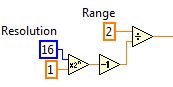
The only place where I can see an example of this is the example 'NOR 5751 finished several acquisition channels'. The conversion to the VI is illustrated below:
It is a 14-bit digitizer, so I'm not the "16" for the resolution.
The text in the example says: "data from the 14-bit a/d converters are represented in the CLIP as compliment of 2, MSB justified, I16.". 2 LSBs are filled with zeros. The data are multiplied by a scale factor (ADC voltage resolution = voltage range / ADC * 16 intervals) to LSB justified data and scale to volts. "This seems to be different from the code above.
I don't understand what is the factor of 16 text. Or I do not understand how they are the same.
Hey JP82,
The 5751 is one of our familiarization trips that produces data MSB justified, with even two most (LSB) containing 0.
If you changed the generetaed of data by the fam to the right by two, then you must use 14 bits resolution.
Example of MSB justified:
Input voltage: 1V
Binary representation of FAM: 0111111111111100Sign bit ^ zero of the LSB ^ ^
Decimal Rep: 32764
MATH:
2 / (2 ^16 - 1) * 32764 =
3.05E - 5 * 32764 = 0.999302 ~ 1V
If he was justified in LSB:
Input voltage: 1V
Binary representation of FAM: 0001111111111111Sign bit. ^
Decimal Rep: 8191
MATH:
2 / (2 ^14 - 1) * 8 191 =
1.22E - 4 * 8191 = 0.99993 ~ 1V
I do not believe that data are two is completed, as indicated in the details. I'll see that this gets fixed.
-
Writing USB DAQ: Reading the data, analyze, analyzed data - does not
I have Labview 2011 32 bits (without tools), on Windows 7.
Material: Enclosure OR USB - 6251 DAQ board. I use analog analog out.
I'm trying to collect data (reading), analyze (like part or derivative) to a new waveform (or a data table)., then convert them this new waveform. As in this example:
http://zone.NI.com/reference/en-XX/help/370466V-01/mxcncpts/hwtimedsimio/
However, I don't have hardware timing.
I tried a lot of things. Those who work temporarily, until the start to write task threw an error: http://i.imgur.com/as5ItdO.png
Another who work temporarily, but it has a 7 second delay: http://i.imgur.com/VLbyZbo.png
Ends up having this error: Warning 200015 occurred
When writing to the buffer during a regeneration, the actual data generated may have alternated between the old and new data. In other words, while the pilot was replacing the old model of the buffer with the new model, the device could have generated some new data, while a part of the old data and then a part of the new data again.
Reduce the sampling frequency, use a larger buffer or refer to the documentation on DAQmx write me for more information on other ways to avoid this warning.
Can someone tell me what I'm missing? It seems very simple.
Thank you.
Thank you for an update. Sorry I missed you use hardware USB DAQ and this is the reason why we see this error
http://digital.NI.com/public.nsf/allkb/EC1968728E660B288625780700570D06?OpenDocument
In general, when you receive errors like that they give you a pretty good idea on what is going on. Therefore, you can try to remove your task AO timming daqmx or try to set the size of the buffer.
This might help
http://digital.NI.com/public.nsf/allkb/E1E67695E76BA75B86256DB1004E9B07
-
AO. MaxRate, AO. MinRate, AO. Properties of voltage. RNGs for hardware DAQ USB-6008
Hello
in one of my report, I use the AO. Property of Voltage.Rngs to see if the selected DAQ card takes in charge the application voltage range. This works very well for my PCMCIA card as well as a PCI card. Now run the same VI with a USB-6008 device, this property gives all the return values. In addition, the report of AO.max.rate and AO.min.rate of the '0', the output is-200197 error properties. I use DAQmx as it is supposed to support the same functions for all DAQmx devices. Can someone please tell me what wrong here and how can I get around this?
Best regards
Gabs
AO.min.rate and AO.max.rate are 0 and error-200197 back because the USB-6008 case supports the outputs analog hardware timed. The description of error is "device does not support this property." There is an entrance to the knowledge base for this question.
By selecting 'Use Waveform' uses the synchronization of the sample clock. The waveform data type specifies a delta t, which is used to set the sample clock frequency. It is not supported on the box USB-6008. You shouldn't set your calendar of sample type or explicitly assign the "On Demand".
The DAQmx driver supports hundreds of different devices. Not all combinations of properties are valid for all devices.
-
Number returned to voltage conversion
I am writing an app to acquire data using PCI cards in VB.net with VS2010. I "assumed" that for a 16-bit card was 65536 heads available for the used range (09:50, etc.). Experience that has not been corroborated. In theory, using the above values, 10 volts volts equal to 32768 and - 10 would equal-32767. I constantly receive lower values.
Can someone tell me if this is correct: there is a 16 bit, 65536 counties map covering the entire map (INCLUDING OVER VOLTAGE RANGE)? In other words, I need 10 volts of input, take this indictment and then entry-10 volts and that would determine my range of work of the charges?
Hey Dan,
If these values are not too crazy about what I expected (not much either).
I guess that it is more a function of calibration and absolute precision.
I would check page 4 and 5 of the technical manual for the 6220:
<>http://www.NI.com/PDF/manuals/375200b.PDF >
It details the absolute precision, given a number of factors that could explain your results.
Also the installation of the samples, you must specifically include in your installation of data acquisition:
<>http://digital.NI.com/public.nsf/allkb/0EA34D565632DFE186256E7B00762DCC >
and then they can be found in the following locations:
<>http://zone.NI.com/reference/en-XX/help/370473H-01/mstudiowebhelp/HTML/locateexamples2010/#netxp >
I hope this helps!
-
DAQ read loop with finite samples
Hello
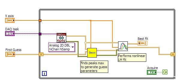
I would like to acquire the data of the instrument with a 6024E Board then put the peaks and which repeat at the highest frequency possible. The task of data acquisition is configured for sampling finished using a trigger, generated by the instrument (55 Hz) signal. When I use a VI such as demo_v1 (see below) everything works well but it takes about 200ms, just for the lu DAQmx VI to run.
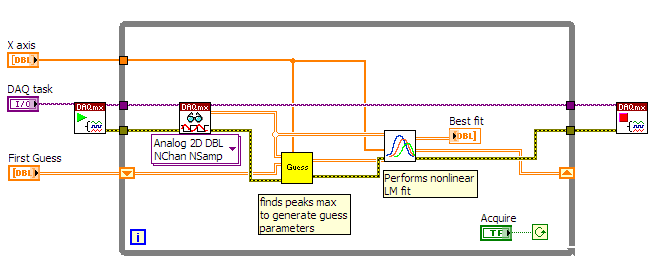
It seems that begin the task outside of the loop (see demo_v2) helps reduce acquisition time, but it no longer works with over sampling. If I configure the task of sampling in continuous synchronization with the trigger of the instrument is lost.
How can I solve this problem?
Bernard
OK, thanks for the clarification.
Another clue would be to use WAS redeclenchables, which means that you combine a Counter task - that is redeclenchables - in order to generate a sample for your Acquisition of AI clock. For example a trigger of your instrument happens every time you take exactly 100 samples with the clock generated by the task of counter.
Christian
-
Just bought a copy of Adobe Photoshop Lightroom but the SuperDrive on my work does'nt Mac. It stops for a few years. Have an another USB SuperDrive, hoping for work, but my Mac won't recognize it. Is it possible to download a trial version and enter here the serial number of the box in the downloaded version
If the second option did not work for you?
From this page:
Error "serial number is not valid for this product". Creative Suite
Click on "Still need help" at the bottom of the page. Follow the path and you get cat or a phone number options
-
Error trying to read the voltage/current off the coast of Keithly 24xx. Help!
Hi all
I am trying to program (keithley 24xx) power to set and an output voltage for a certain period of time. I wrote cela all on labview and it works very well. I then added the ability to read and display the voltage output and current on my exit sign. ATER, I did, after the end of the time, run time, I'd get a beep and this error:
Keithley 24XX.lvlib:Error Query.vi
Reports of the instrument:
803, 'not allowed with OUTPUT.
0, "no error".------------------------------------
«"" "String of full appeal:»»"»
Keithley 24XX.lvlib:Error Query.vi
. VI 24XX.lvlib:Read (Multiple Points) Keithley
. VI 24XX.lvlib:Read (Single Point) Keithley
Basic_Operation.VI-------------------------------------
My guess is that the output turns off while reading is still ongoing, creating this error. I tried to find a way to fix this problem without success. Any ideas? I have attached a screencap of programming
Thank you!
You are the ' turn off before that can't read. When the time is true, the output is cut. Why do you even exit to activate it inside the loop? Make the first function outside the loop so that it is called after the loop stops.
-
Using the DAQ USB-6009 meter and an analog input voltage at the same time.
Hello
Currently, I'm reading the two channels of voltage with the USB-6009. It happens that one of the channels is the output of a digital coder, and it would be much easier to use it directly to the PFIO entry that is defined as a counter. The problem I am facing right now, it's that I can't use the DAQ Assistant to use the analog voltage to a channel and the digital channel counter at the same time. Once I put the DAQ Assistant to read the input from analogue voltage, I won't be able to add analog inputs. And as I put the DAQ Assistant to use the PFIO as a counter, I can add more entries to read analog voltage is.
I wonder if it is possible to solve this problem using the lower level data blocks? Another solution would be to read two channels in analog input voltage and that the use of Matlab to process data resulting from it, since I was not able to do the counting to work simultaneously with the acquisition in Labview to impulses.
Hope you guys can help out me.
Thanks in advance.
Using a simple wizard of DAQ is incorrect. You need one to acquire analog inputs and one for the meter.
Maybe you are looking for
-
Hi allAfter installing sp2, the function key does work more (fn + F8), so I don't know how to turn on Bluetooth. With bt Manager, I can't because a new link I get an error message such as bt is not ready. Does anyone know how to solve this metter, I
-
DeskJet 5150 driver for Windows 7 (64-bit)
How can I get a Deskjet 5150 driver for Windows 7 (64 bit)? I have recently added a new laptop with Windows 7 on a small home network (using working groups) and want to be able to use the existing printer 5150. Thank you Stephen
-
iI has downloaded a file from eopenbox when I tried to open it I tells me safari cannot open the file because there are no applications available, how do I do this. Rob
-
Installer Help folder inside %Program Files% permissions
So, I just created an installer on my Win7 machine, and I'm running into problems. Let's call my request "MyApplication.exe". The application is installed in "C:\Program Files\MyApplication"... which is great. It also creates a couple subdirectories
-
Screen white (on two laptops) from Microsoft update!
I have TWO laptops that have developed the same so-called 'fault' which, according to microsoft is a mistake of the laptop I read of another user on this forum to have the same problem. Both my laptop suddenly develop these flaws strangely the same d