Waveforms digital output duty cycle glitches
I try to use a square wave converted to digital output to operate some solenoids but seeing some problems with the cycle on the digital waveforms. The output frequency will always be of the order of 1 Hz and duty cycle must be adjustable to integer values. I have attached a simplified below, demonstration that shows the digital/analogue output VI I used initially. the problem with this VI, is that if I choose a cycle that is not a multiple integer of my samples for waveform I get seeds. If I use the Boolean digital VI table this problem disappears in my simplified code, but in my real program the problem reappears.
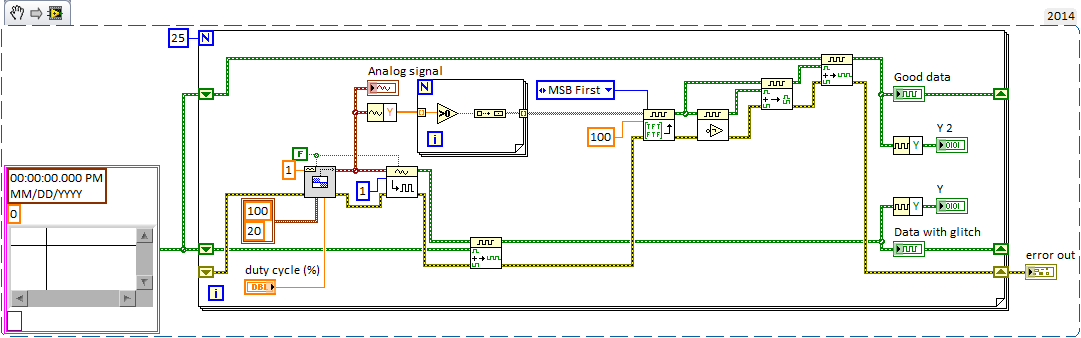
This image shows the waveform analog generated as well as the digital output that results.
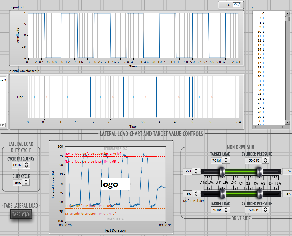
In the digital waveforms, you can see that the duty cycle of 50% is sometimes applied during the single loop (~.2us) instead of more than 1 sec iteration, although the curve of actual load indicated in the table at the bottom seems to suggest that LV ignores this glitch (somehow). As I said, the problem disappears if the duty cycle is an integer multiple of the sample/loop. Timing of the loop is torn apart by other e/s to 2 000 Hz/400 samples per loop and 100 Hz/20 samples per loop (large enough VI otherwise I would include it). Obviously, I could change them to get 50% as a multiple, but this does not solve the problem if user needs to adjust from there.
Can someone point me in the right direction here? I'm sure that there is a stupid/easy solution, but I can't seem to get.
Thank you!
You might try turning the inputs A and B of waveform of the VI of the digital samples append. It seems that A should be the fate of the shift register data (the original data) and B should be added (the new waveform) data anyway, at least conceptually.
Paul P.
Engineering applications
Tags: NI Software
Similar Questions
-
How to generate the digital output of the variable duty cycle and clock source being contrary?
I want to generate a digital pulse every front amount of my pulse counters. He must have a variable duty cycle. until now, I've been able to generate a digital output, but I can't change its duty cycle.
pls tell how I should proceed?
Thank you in advance...
-
I use the PCI-6723 card and I am trying to produce a model of waveform using the analog output channel. The wave consists of 5 different voltage levels. The main problem is that the first 4 voltage levels are supposed to have 926 microseconds time intervals and the time interval the last voltage level is supposed to be 1,296 milliseconds. In addition, the waveform must be triggered on the trailing edge of a sample clock of 200 Hz with a 0.1% Duty Cycle. Is it still possible? If so, any help would be greatly appreciated. Thanks in advance!
Here is what I currently have, but it does not fulfill my purpose.
 int32   written;
    float64 data[5] = {-0.23, 0.38, 1.12, 1.78, 0.10};  //volts
    //long  time[5] = {  926,  926,  926,  926, 1296};  //microseconds

    // DAQmx Configure Clock
    DAQmxErrChk (DAQmxCreateTask("",&taskHandleFRQ));
    DAQmxErrChk (DAQmxCreateCOPulseChanFreq(taskHandleFRQ,"Dev3/ctr0","",DAQmx_Val_Hz,DAQmx_Val_Low,0,200,0.001));
    DAQmxErrChk (DAQmxCfgImplicitTiming(taskHandleFRQ,DAQmx_Val_ContSamps,1));

    // DAQmx Start Code
    DAQmxErrChk (DAQmxStartTask(taskHandleFRQ));

    // DAQmx Configure Code
    DAQmxErrChk (DAQmxCreateTask("",&taskHandle));
    DAQmxErrChk (DAQmxCreateAOVoltageChan(taskHandle,"Dev3/ao0","",-10.0,10.0,DAQmx_Val_Volts,NULL));
    DAQmxErrChk (DAQmxCfgSampClkTiming(taskHandle,"/Dev3/Ctr0Out",1000.0,DAQmx_Val_Falling,DAQmx_Val_ContSamps,5));

    // DAQmx Write Code
    DAQmxErrChk (DAQmxWriteAnalogF64(taskHandle,5,0,10.0,DAQmx_Val_GroupByChannel,data,&written,NULL));

    // DAQmx Start Code
    DAQmxErrChk (DAQmxStartTask(taskHandle));
Bingo. This code seems to work much better. Looks like I had to reduce my number of samples per 1 to fit the waveform desired in 5 milliseconds of the sample clock delay.
However, if someone knows a better way to achieve these results, I am open to all ideas.
void CDevDlg::OnRdr1e1() { float64 data[4000]; float64 volt[5] = {-0.23, 0.38, 1.12, 1.78, 0.10}; //volts int x=0,d; for(int v=0; v<4; v++) { for(d=0; d<741; d++) { data[x++] = volt[v]; } } for(d=0; d<1036; d++) { data[x++] = volt[4]; } // DAQmx Configure Clock DAQmxErrChk (DAQmxCreateTask("",&taskHandleFRQ)); DAQmxErrChk (DAQmxCreateCOPulseChanFreq(taskHandleFRQ,"Dev3/ctr0","",DAQmx_Val_Hz,DAQmx_Val_Low,0,200,0.001)); DAQmxErrChk (DAQmxCfgImplicitTiming(taskHandleFRQ,DAQmx_Val_ContSamps,800000)); // DAQmx Start Code DAQmxErrChk (DAQmxStartTask(taskHandleFRQ)); // DAQmx Configure Code DAQmxErrChk (DAQmxCreateTask("",&taskHandle)); DAQmxErrChk (DAQmxCreateAOVoltageChan(taskHandle,"Dev3/ao0","",-0.5,2.0,DAQmx_Val_Volts,NULL)); DAQmxErrChk (DAQmxCfgSampClkTiming(taskHandle,"",800000,DAQmx_Val_Rising,DAQmx_Val_ContSamps,4000)); DAQmxErrChk (DAQmxCfgDigEdgeStartTrig(taskHandle,"/Dev3/Ctr0Out",DAQmx_Val_Falling)); // DAQmx Write Code DAQmxErrChk (DAQmxWriteAnalogF64(taskHandle,4000,1,10.0,DAQmx_Val_GroupByChannel,data,NULL,NULL)); } -
Duty cycle of measurement using digital inputs DAQ
Hi all!
My system has a PXI-8269 card and I want to measure the duty cycle of the Digital PWM signal generated by a device.
To acquire this signal, I'll use a digital DAQ (PFIx) instead of a counter of data acquisition (CTRx) (they are already used for other applications).
The search of the database of examples, I found live who use meters. So I wonder if it is possible to do that and how could I.
Thank you!
Sorry, the correct reference is PXI-6289.
I was determined to acquire a digital waveform, converting it to an analog waveform and then using the correct function in the range of functions->-> Analog wave.
Thank you!
-
How can I write a digital waveform to the digital output (traditional DAQ)
Hello
I use a NI 6023e, PCI, with 8 digital outputs. I generated a digital waveform. How can I write for a specific digital production line now?
I only have Labview 7, so I can't use DAQmx.
Thank you very much
-
I use a counter that is generated by a PCI-6110 to switch a relay to solid state that enables or disables a heating unit. I update the duty cycle based on the output of a PID controller (0 - 100 output of PID VI gets scaled to a cycle of 0.001 to 0.99). The question is after two iterations, the written property node is no longer the output of PID on the scale to the task and it seems 0 as the default value.
Many meter generation examples use event structures to detect a change in the duty cycle and pass that to the task. But structures event detect changes in values if the value is written in a local variable and not typed in a CNC? I feel that the answer should be 'Yes'... but in the case I tested it seems to be 'no '.
Don't adjust the precision of a digital indicator / control limits the number of significant digits does a calculation? I would limit my duty cycle to 2 decimal places - i.e. 0.3342 and 0,3313 the two would be 0.33. In this way the cycle is not unnecessarily updated.
The temperature is read by a PCI-4351... which may arise under? blocks if you have not installed the drivers.
arcranda wrote:
Many meter generation examples use event structures to detect a change in the duty cycle and pass that to the task. But structures event detect changes in values if the value is written in a local variable and not typed in a digital control?.
To have a triggered event when a value is changed programmatically, create a Value property node (signaling) and the new value of wire to it. This will trigger a change of value for this variable event.
arcranda wrote:
Don't adjust the precision of a digital indicator / control limits the number of significant digits does a calculation? I would limit my duty cycle to 2 decimal places - i.e. 0.3342 and 0,3313 the two would be 0.33. In this way the cycle is not unnecessarily updated.
.
Changing the properties of display to show only 2 decimal places does not change the numeric value stored in memory. You would have to round up the digital to two decimal places. To do this is to multiply the number by 100, change of an integer (this will lose the remaining decimals), then divide the result by 100 to get again the two decimal places. When changing to an integer, you will need to round to the nearest integer to make 0.3299 0.33.
-
How to synchronize 2 digital output channels that have been created with DAQmxCreateCOPulseChanFreq
Hello
I use peripheral USB6221.
I created two digital output, operating on a frequency of 75KHz and duty cycle of 50%. But I need a period of 1 microsecond between the two channels.
I have craeted the two channel on the same task and guess if I use a delay of 0, the channels will be synchronized, but looking at the scope, the channels are not synchronized. Here's the code I used (I checked also all return codes of coarse and fine).
Thank you
Danny.
Int32 RetCode;
RetCode = DAQmxCreateTask ("", & m_OCtaskHandle);
LogMessage (RetCode, "CreateTask", "");
If (RetCode > = 0)
{
define the first output channel for 1 transmitter (75KHz)
RetCode = DAQmxCreateCOPulseChanFreq (m_OCtaskHandle, "/ Dev1/ctr0", ")
"Transmit1 Line 1", / * name to assign to the channel * /.
DAQmx_Val_Hz, DAQmx_Val_High,
0.0, / * initial delay in seconds * /.
75000.0, / * Freq * /.
0.5 / * market factor * /);
define the second output channel for 1 transmitter (75KHz with 1 microsecond delay)
RetCode = DAQmxCreateCOPulseChanFreq (m_OCtaskHandle, "/ Dev1/ctr1", ")
"Line2 Transmitt1", / * name to assign to the channel * /.
DAQmx_Val_Hz, DAQmx_Val_High,
0,000001, / * initial delay * /.
75000.0, / * Freq * /.
0.5 / * market factor * /);
Describe all channels continuous task
RetCode = DAQmxCfgImplicitTiming (m_OCtaskHandle, DAQmx_Val_ContSamps, 1000 / * I think that NA since continuous * /);RetCode = DAQmxStartTask (m_OCtaskHandle);
Hello Danny,
If you are looking for more output channels of the Digital pulse trains, you can create 1 task of counter that is used as the clock for digital multi-line data output. For this digital task, you will need to make the clock source line PFI for the output of your task of counter. Once this has been done, you will need to create the digital signal for each line of output and write to the card. The example called write dig Chan - Ext Clk will explain how to set up the digital task so that the task has an external clock (the counter). I hope this information helps you and if you have any other questions, feel free to post.
-
clock calendar - digital output
Hi all!
I need timing equipment impliment on a few digital output lines. That's what I have so far:
I didn't get an oscilloscope for her yet, but I'm fairly certain that it works. Please note that in this example, I use a PCI-6115. I have 2 questions:
(1) make what I do look reasonable at a quick glance?
(2) I'm kinda mistified by the entry of clock source to the example of the clock function. The analysis that I read just still confuses me. I understand that the clock is what dictates the sequence of material. I do not understand how to choose the appropriate clock source correctly. More specifically, in the above example, I've only had the program work when I chose "20MHzTimebase". What is c? Why this work?
When I try to select ' Dev1 / / SampleClock ", I get the following error:"attempted to perform a route when the source and destination are the same point."
When I try to select "Dev1/PFI0" or "RTSI0/DEV1", I get a timeout error in the wait_until_done.vi--> it does not appear that the waveforms are executed.
That means the PFI and RTSI acronym for, and why they appear as options when you select a source of the clock? Furthermore, why have they not worked as a clock source?
I would be very grateful to anyone who could clear things for me a little. Thank you!
Have you read the http://digital.ni.com/manuals.nsf/websearch/01C075FB9478F94A8625786A007435BA? manual The definition of PF and RTSI are here. They are designed using external clock signals. You have the choice of using the internal clocks of analog output (20 MHz) or external clocks. If you do not connect the RTSI bus or PF what, whether you have no clock so no data will be output. Selection of as source does not work because it is not a source. You provide a source for it.
-
How can I more easily generate a pulse of digital output of finite length?
Hello
I need to open and close the two pneumatic valves using a TTL output (without load current or the output power) using a PCI-6280 or PCI-6601. The valves must open almost simultaneously and closing after different amounts of time elapsed (millisecond level timing, maybe 100 microseconds-level timing at worst). My current plan is as follows:
-Create a task with two digital outputs (type of waveform) and another task with a counter that generates a frequency set by the user (I know I can use the generator frequencies on one of these cards, but I would have preferred a counter - the best selection of frequencies).
-Wire the output of the counter at the entrance to clock two digital outputs.
-Output of the meter is digitally triggered by another digital channel which I use to control if the pulse goes out. Through its counter node, it is programmed to be redeclenchables.
-Two digital waveforms are drafted who have both consist of unique active high pulse (i.e. signals go ' down (for the amount of time user-defined) - low ".")
-These signals is written to their respective ports and their tasks have started, as is the task of the meter.
-Whenever the user wants to open taps, digital triggering is sent up and then back to low (this can be done with synchronization software, because it is not exactly when the fire valves). Whenever the user wants the valves open for a different period, different digital waveforms are generated and written in the buffers of the digital output channels.
My problem is that it looks like a lot of effort for me to go and I wonder if there is a much simpler solution, that I don't know everything. You can program a computer to produce a pulse of finite length? Is there a faster way to program a digital output for that channel?
Thanks to anyone who responds to their help.
It is certainly instructive. Thank you.
The thing is, I have only six total counters to work with and I have a lot of time to do things. To use these solutions, I would need to use 4 or 6 account counters required to my needs.also that I would need to synchronize their departures.
Overall, I stick to my method for now - less system resources and synchronization can be don by using the same meter of finished output clock and not to use a trigger to all.
Once again, thank you for your help so far.
-
Digital output with timer (Simulation)
Hello everyone, I just found out how LabVIEW program a week ago. I try to do a simulation of digital output by LabVIEW (my attachment). In this simulation, I have a slider as an input (0-10 V), two digital controls (upper limit and lower limit), a waveform graph draw these 3 evaluates and two Boolean LED (P0.0 and P0.1) as indicator. In this simulation, you can fill any number (between 0 and 10) in numerical order as a limit for your entry cursor. If the entrance of a cursor exceeds these upper and lower limit, then the Boolean LED lights, P0.0 so exceeds the upper limit, and if P0.1 exceeds the lower limit. The problem is that I do not know how the timer for those Boolean LED. As an example:
(1) make an entry of cursor,
(2) if entry (1) exceeds the upper limit, P0.0 lights for 5 seconds, then turn to during 10 second.
(3) if only 10 seconds, you change the entry back to normal (between high and low limit) then P0.0 will stay turn of until the cursor entry exceeds the upper limit again,.
(4) If, in this second 10 you has not changed the entry (the stay exceeds the upper limit) then P0.0 repeats the process (2) until you the entrance to cursor back to normal.
(Same process for entries exceed the lower limit).
Can you help me do this timer? Thank you

Concerning
Juventom
Hello
If you don t mind I would just give you some advise to your code. To determine the data stream you can also use only the error wire connected to the loop. So Don t you really need, it's beter not not to use variables. For your solution, you can use something similar to what I tried for the upper limit in your program. It is added as an image.
Hope it helps
-
Well, I thought I had everything figured out, but we have finally had time to go to our lab and test it and there seems to be a problem with the output digital here. I'll look at what's the point of this VI, then describe the problem
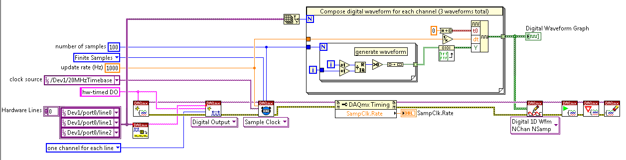
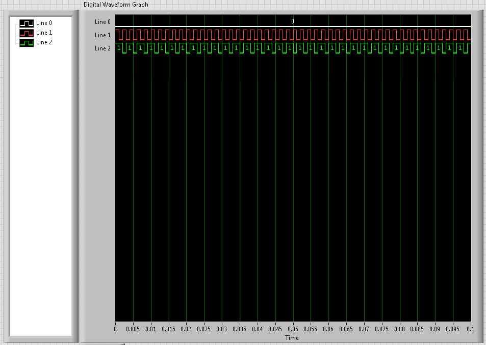
Analog input is entered and analyzed as digital outpt is sent several lines (3). The digital output is used to send a single, user‑defined delayed pulse TTL with other instruments like triggers. I put this program to create an array of digital waveforms for each channel, each of them are of the same length as the analog input. '1' is inserted in the appropriate place in the table, in lieu of a value of '0', creating the required table. This table would be written on a digital line (1 channel, samples of N). Three of these subVIs are used here, so three signals various tables are created and writtin in its respective lines when the program runs, the analog input seems to work very well, but that a single digital output is executed. I need all three lines to write simultaneously.
I use a USB-6221 with LabView 8.2
I have attached all the files needed to run this program, and if the 'LabView programs' folder is saved on the C drive, I think that the paths of the files must be correct.
Thanks in advance
Hi Chris,
Hello and I hope that your well today.
Thanks for your updates.
I think that my being better if we start from the beginning.
1 could you try the example Correlated Dig writing with Counter.vi from the Finder of example of NOR?
It produces output meter as the time base for the digital output - to get clocked at digital output. Don't you see the waveform being printed on your outings that match the graph of digital waveform on the front panel?
If not, try to use one of the other examples, as Scripture Dig Port - this is a single VI just to send a single value for each digital line. If this does not work, there is a connection problem.
2. If we got this far without problems, then the next part would be to change the waveform so that you could write the data that you want to...
The digital waveforms can be made a boolean table, then using the array of Boolean DWDT to Digital.VI to convert into the type of digital waveforms. The waveform will have X number of samples. Therefore, at each clock pulse, you will produce 1 sample on each channel. So if you set the rate for 1000 and the number of points to 1000 (samples) it will display the waveform on a second. (as his continuous the DAQmx will make a loop through the buffer and start out of the waveform again).
Note, have you seen the palette of digital waveforms? It is located under waveforms and has more vi like the Boolean DWDT to digital.
Please let me know how you go.
-
Acquire the values only when the digital output is high.
Hello
I work with test of transistor, whose door is controlled by the digital release of USB6289, related to BNC2120.
Test plan:
Door 1.transistor is enabled for 5seconds, with P0.0 for example
2. then, everything remains off for 1secondes.
3.p0.1 is used as digital output to activate the circuit passing him curent through in the opposite direction, P0.1 goes high for 3 seconds, PS: Gate is off.
4. the same cycle repeats again.
My question is to store values to the output of the transistor when P0.0 and P0.1 goes high, and these values should not change until my digital outputs respective again go high.
I can access transistor by continiously read out my power supply values.
and in the State off I want to read AI0 because at that time, my power supply is off, so that I can activate the circuit to pass the current in the opposite direction.
Again, my question is to gain the output through power value when P0.0 is high and store them until the transistor turns on.
and even for P0.1, acquire the value of output through AI0, when P0.1 is high and store it until it goes high again.
Hopefully, I'm able to explain my problem clearly.
Please help me.
Concerning
Anurag
Think about what States (object:statemachine and determine when to use sequence Structures) do you want from t0... t(n-1), IF DAQmx generates outputs and/or inputs are absorbed and what needs to happen (event timed out), before move you on to the next 'State '.
type def 'enum' with your different States:
- initialize
- wait (the user initializes times (sec) set for States, or whatever and presses button 'Start')
- T0 (generate DigOutputs, store acquired data AnalogOutput (string output number) the register shift, before moving to the next State > user 'set time' must elapse (Note: the wait function allows you to control the rate of execution of loop and allow the CPU to respond to external events and system tasks and avoid using wait functions at the same time an operation of software...))
- ...
- t(n-1) if ' end (made requirement) "> goto 'stop', ' another (not requirement not)" > goto regardless of 'State '.
- stop
- write a text file of data (string).
-
Hi all
I have never done in time real before LabVIEW and have a pretty simple question.
I know that there is a measure of pulse width as VI in the palette of waveform and it can be used to measure the duty cycle and frequency of the PWM. My question is, is it necessary to use this measure of vi on a platform time pulse width real (compactRIO, compactDAQ etc...) so that it works? In other words, can I just use normal LabVIEW to measure the duty cycle and frequency of the PWM?
Is there an alternative to the duty cycle and frequency of measurement without using compactRIO or compactDAQ platform? My concern is because I did no real time programming and the deadline is tight and there is not a lot to invest in learning programming in real time.
I just want to know the experiences of others who have done it before.
Thank you
Yours sincerely,
chati
Oh yes RT is not really necessary for sample DAQ of things like that. If you have a condition like assess each cycle of a PWM, and if the signal falls then to send a command within the period of a cycle, then you want RT or FPGA to respond deterministically. But if you agree with a bunch of samples taken, then evaluate the data after having been taken then a cheap DAQ card probably will work fine.
Speed can be a matter of concern. Lets say you have a square wave of 1 kHz at 50% duty cycle. If you enjoy at 2 kHz, then you should be able to see that the signal is weak for a sample, then up for a sample and you can determine that the signal is at duty cycle of 50%. But if you have your wave to the duty cycle of 10%, while most of the time, you will see two samples of low, thinking that it's 0% duty cycle, but then from time to time you will get a top and a bottom and get 50% of reading, who don't agree.
This is why it is recommended that you enjoy at a rate at least 10 times faster than your input signal. So if you have an example of signal of 1 kHz to 10 kHz. Then, if your duty cycle is 10%, you will see a small sample of top and 9. But even that might not be enough if you need to have more precision to your measurement. Fortunately, NEITHER sells cheap and expensive material for that. The hardware cheaper that might work for you is the following:
http://sine.NI.com/NIPs/CDs/view/p/lang/en/NID/212383
or perhaps cela
http://sine.NI.com/NIPs/CDs/view/p/lang/en/NID/212384
But you probably want to call OR and describe your situation and they can recommend the best material to use if you are not familiar with their offers. Depending on your situation, you may be able to use an Arduino too. NOR has a toolbox where it can collect samples and send them via USB. The sent message can be the rated frequency and the duty cycle, but once again it is quite limited and does not have any help from NEITHER a material point stand, they provide just the box tool.
-
Route of the exits of the same meter, digital output
Hello
I'm not sure it's possible, but I will deliver the outputs of 2 meters (PCI-6602) on the same line of digital output.
My 2 meters each generate a pulse train defined by frequency, cycle of dut and delay. I want to combine 2 pulse trains in a pulse train resulting. How would it possible if I can't deliver the outputs of the counters on the same digital line? What I have to abandon this idea and set the desired binary pulse train and release several times what a digital line?
Thank you very much in advance for all your comments here.
Cheers, Shaun.
Hi Shaun,
I do not recommend you to connect directly 2 outputs.
Why not use a door or 2 entries? Connect the outputs of the meter to the doorways.
If the impulses are well timed and synchronized (they do not appear at the same time)
the output of the gate or will be a combination (in short, actually) of these pulse trains.
Hope this helps,
-
Issue of two-channel digital output
Hello world
I need some aid on two output digital channel design
In short, I want to use a PCI-6731 with BNC2110 output. Two digital output channels will be used, eg Dev1/port0 / line0:1. I hope that $line0 could output a stable finite samples in f1 (for example 10 kHz) frequency and the total number of samples as N1 (e.g. 1E6); in the meantime, I hope that line1 could output samples finished frequency f2 = f1/M (for example 2 kHz) and the number of samples as N2 = N1/M (e.g. 2E5). In other words, I expect $line0 and line1 out same time length samples with different frequencies and different number sequence. Please note that setting should be controllable, and sometimes N2 and f2 are not exactly an integer (then we take round value).
Thank you for your help in advance.
Joined a vi that does what you want, I think. It uses two digital outputs timed by a meter. The digital outputs are fed waveforms generated by two frequencies with a full report. You can change the part of the code that generates the waveform as you wish and use the rest to make the exit.
Richard
Maybe you are looking for
-
After the update to Firefox 23 I had a lot of problems. The major problem I had is that Firefox uses up to the amount of memory RAM (from 2 GB for less than 5 tabs assets/load) and ends up crashing. After a few tests, I found that when I closed the t
-
Today, I was doing my normal thing to talk to my friends on Skype. I had to restart my computer, did it, and now the program even used open. When I run it in admin it appears on my Manager tasks for about 3 seconds and disappears while nothing appear
-
Is Gvyoe a Microsoft program or folder?
Microsoft Security Essentials, says that he is a potential threat, but it does not get rid of it. On my computer that has Windows XP Media Center, it is in C:\Documents and Settings\Geezer1946\Application Data\Microsoft\Gvyoe\gvyoe32.dll. I would jus
-
The HP Pavilion dv6 laptop computer bios password
I need to access the bios of this laptop and it has a password. When I entered the password 3 times he gave me this code 53701078
-
Cannot receive emails with attachments such as .xls or .jpeg
Since this weekend, I was not able to receive e-mails with attachments, other than documents parts Word. I did not change my Live Mail or my e-mail address and password. I am getting following error codes when it expires: Can't send or receive messag