Digital output with timer (Simulation)
Hello everyone, I just found out how LabVIEW program a week ago. I try to do a simulation of digital output by LabVIEW (my attachment). In this simulation, I have a slider as an input (0-10 V), two digital controls (upper limit and lower limit), a waveform graph draw these 3 evaluates and two Boolean LED (P0.0 and P0.1) as indicator. In this simulation, you can fill any number (between 0 and 10) in numerical order as a limit for your entry cursor. If the entrance of a cursor exceeds these upper and lower limit, then the Boolean LED lights, P0.0 so exceeds the upper limit, and if P0.1 exceeds the lower limit. The problem is that I do not know how the timer for those Boolean LED. As an example:
(1) make an entry of cursor,
(2) if entry (1) exceeds the upper limit, P0.0 lights for 5 seconds, then turn to during 10 second.
(3) if only 10 seconds, you change the entry back to normal (between high and low limit) then P0.0 will stay turn of until the cursor entry exceeds the upper limit again,.
(4) If, in this second 10 you has not changed the entry (the stay exceeds the upper limit) then P0.0 repeats the process (2) until you the entrance to cursor back to normal.
(Same process for entries exceed the lower limit).
Can you help me do this timer? Thank you
Concerning
Juventom
Hello
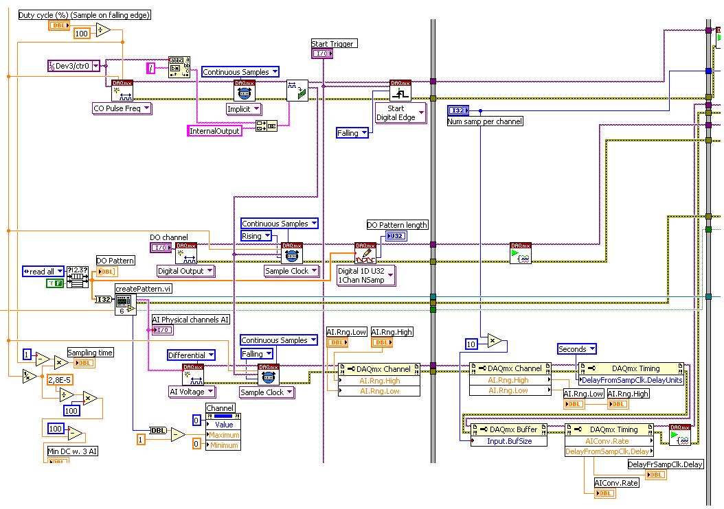
If you don t mind I would just give you some advise to your code. To determine the data stream you can also use only the error wire connected to the loop. So Don t you really need, it's beter not not to use variables. For your solution, you can use something similar to what I tried for the upper limit in your program. It is added as an image.
Hope it helps
Tags: NI Software
Similar Questions
-
Synchronization of analog and digital output with the external sample clock
Hello
First of all sorry for my English, I will try to explain what I want to do.
I want my PCIe-6321 to send two custom signals (modification sawtooths) on a mirror controller. I would also like to generate output with my card at the beginning of each tooth of saw. Everything must be synchronized with an external k-clock signal of 100 kHz. The idea is that whenever the PCI receives a trigger to external clock, it sends two analog output voltages and when he received 1024 clock ticks it will also send a pic of triggering TTL. What I do is first prepare the map and after that in a loop sending and modifing the output values of the two signals and at the same time send a digital signal Boolean in each arch, so when's done it 1024 iterations of the loop I send an event to the digital port. Attached you can see.
The problem is that I don't know how to synchronize both. Can I use the sample clock just to the analog output? I can use sample for the two outputs clock, or do I need to use the output of the meter? If don't know how to use it here.
If I do nothing else bad/wrong, I would be grateful for feedback.
Thanks in advance,
PabloI don't know how but I find the solution. I'm generating more than a positive value (as I was triggered maybe very fast the oscilloscope has been absent there). If I put the sample clock of digital output to use the sampling/ao/Dev1 clock that it doesn't, but if I put to use the same source as the OD (terminal where my external clock is connected), but the trigger to start the DO to be Dev1/ao/StartTrigger this works. I don't really know why, but it does.
Thank you for your patience and your help. I put here the final code.
-
Implementation of multiple digital outputs with a box USB-6009
Hi all
I write the code to implement a USB-6009 multiple digital channels, digital outputs independent. I have configured the function of "DAQmx create Channel" to create 'a channel for each line', but I can't understand how to access and control these channels separately. Pointers would be greatly appreciated.
Thank you!
I thought about it. Never mind.
-
Digital output with NOR-9401 in cDAQ-9174
Hello
I have a cDAQ-9174 with an e/s digital NOR-9401 module. Now I want to output Digital signals on line0:3
$line0: Boolean 1 time = 10ms
Line1: Boolean variable 1 time = 20ms
row2: Boolean variable 1 time = 30ms
line 3:20 pulses (period = 250us, duty ratio = 0.5) after a time = 40ms
the value of line0:3 must be Boolean 0 after 45ms
Can someone let me know what I need to work to solve this please?
Thank you all for your help.
Concerning
Bing
Thank you Christian for your quick replay.
I have some experience in programming of microcontroller with C. I learned LABVIEW for about 1 month and followed a lot of demons in line and tutorials. I know that nodes DAQmx Data Acquisition screws and fundamental property.
As I said at the beginning on the $line0, lin1and line2, they serve to control the relay in my circuit. 10ms could be controlled with the OS clock. Pulse of line3 series is used for IGBT gate signals, which is the critical moment. I want to use the clock machine to accurately control line 3 and synchronize at the same time the pulse with analog inputs from an another two NI9206 modules in the same cDAQ chassis.
I just want to know more on the digital line demand signal relay output and a correlation between the line of analog input-synchronized finished pulse output. Waveform diagram is locked.
Thank you.
Bing
-
Simultaneous analog inputs and one digital output (with NI6221M). Critical moment.
Hello!
Please excuse my bad English.
Idea:
I developed a device to measure the absorbance of light in the sample. The device will have 20 light emitting diodes (led) and 30 light sensitive photodiodes (DP). I have a PCI NI6221M card. As there are a lot of LEDS and PDs the device must use external multiplexing (MUX). The Assembly is shown in figure "DOAI System.JPG". "delta t" figure is not important. It may be zero, one or a few Americans. It is not essential for the operation of the device.
Opreation:
PD 1 will be multiplexed to the AI and the LEDs blinked (turned on and outside), one at a time. Then 2 PD will be multiplexed to the AI and again all LEDS flashing one at a time. The sequence continues with 3 PD, PD 4 and so on. Each blink a led should produce a sample of I. The sampling frequency of the AI should be about 12 kHz (so 80us for example).
Q: It will be possible to obtain from the Commission of NI6221M?
Problem:
I realize that there will be problems. When c generates an address on the MUXs there will be a delay until the LED driver, PD and input amplifier electronics of HAVE it settled. Q: Is it possible to delay the sample clock HAVE some 10 microseconds as to allow that to happen? (Perhaps use an internal counter operating on a basis of time much faster than 12 kHz sampling or use another for me still a feature is not known. May actually leave the sample clock HAVE be the 'master' and instead of delay clock.) Please see the "" calendar of GOT it. "" JPG ".
Q: Is it possible to control the time to settle for AI? That is to say that he can use the 6221, say, 30 US to settle before it reads the value. What these 30 arrive us before or after the flank of sample clock?All reviews are much appreciated,
Markus
Hello!
Just thought I should fill this thread by posting the code that we use now. The moment is as before, but we've added a few nodes property to coacha few parameters. In addition, 6221 has been replaced by a 6259Usb device that allows us to have the best insulation galvanic and more synchronized digital I/o lines.
-
Digital output to a different voltage?
Hi all
I finally finished my program of data acquisition for the laboratory, which made the acquisition of AI voltage multi-channel digital outputs with timed to control the gas valves. My post-doc asked an additional feature, however, which must be able to have the analog output... It turns out that what he really wants to do with the feature is to have output digital, but with a different voltage value (he never hears on the sending of information higher or lower in a simple experiment).
Now, the program is set up to run digital output now, it would be quite a bit of work to change in a zone of OCCUPATION. Is it possible to simply change the settings somewhere to have the ups to DO at a different voltage? I hope that this is the case from a card of 10 dollar Arduino can do 5V or 3, 3V. Our DAQ card is the NI PCIe-6353. I looked through the data sheet and found nothing.
Thank you.
p.s. I suggested using additional circuits to set the tension for a given experiment. The post-doc said it was possible, but inconvinient. :/
RaymondLo wrote:
p.s. I suggested using additional circuits to set the tension for a given experiment. The post-doc said it was possible, but inconvinient. :/
Well, it is just too bad for the post-doc. Maybe he should give you better requirements next time

OK without being in a bad mood, it is not a way to change the digital output voltage. When you talk about DIO cards really aims to communicate only high or low and have a voltage. The only other option would be to use 4 AO ports on the card and treat them programmatically as DO.
-
Hallo,
I use the following system:
- OR PXI-1044 with controller NI PXI-8109
- OR PXI-2564 switch module to turn on the monitor of my test device
- Data acquisition multifunction NI PXI-6259 to measure the signal that responded to the questionnaire jump
The two cards are the same - PXI trigger bus. For both, PXI-2564 and PXI-6259 I use DAQmx to set the reading and writing of the channels.
Now, I want to measure the time between the digital output, my unit turns and the analog input, which measures the response of my system.
I can't do work by myself, please help me!
I thank Ludwig.
Hi Ludwig,.
If you can't give us any VI we have difficulties with to help you.
Because I Donat knowledge how your program is mounted it is not easy to know where you should enter signals.
Here's a question similar to yours:
http://forums.NI.com/T5/LabVIEW/best-way-to-measure-time/TD-p/178704
and 2 external links:
http://www.ehow.com/how_8698983_measure-time-LabVIEW.html
http://objectmix.com/LabVIEW/385152-how-can-i-use-LabVIEW-measure-time-between-analog-pulses.html
-
Problem with a digital output in the information of an analog input
Hello
I use a SCXI-1000DC module with a module of the SCXI-1600, SCXI-1531 module and SCXI-1163 module to receive an analog of an accelerometer signal and a digital signal.
I claim that the accelerometer is constantly monitored, and the output is on when I want to, by an impulse that I comand in labview.
I use a rate 25 k and a 12, 5K samples per channel on DAQmx Timing.I notice in DAQmx read, if I put a sample of hight by channel, the output is not there when I want to, and if I put a few samples per channel, I exit when I want to, but the program seems to be slow with the passage of time. I don't know how I can solve this problem!
I'm sorry for my English, and I hope you can help me.
Thank you
Silvia
Hello Silvia,.
If you ask a larger number of samples, the labview diagram will stay longer in the DAQmx Read function, so the while loop runs slowly, and the digital output is updated less often.
I suggest that you use 2 separate while loops: one for the analog input and the other for digital output, so that each loop might run at a different speed.
Best regards
-
digital output microsecond LED timer
Hey all,.
I'm doing a table of 10 LEDs in a row to form an analog timer to use to characterize the delay of the shutter on a digital SLR. We'll first stage shutter lag on the camera using a method different and well set the delay of the shutter for interior<1ms. i="" am="" trying="" to="" use="" labview="" alongside="" a="" ni="" usb="" 6251="" using="" an="" sc-2345="" for="" access="" to="" the="" digital="" outputs.="" im="" using="" a="" timed="" structure="" and="" a="" timed="" loop="" to="" ensure="" the="" timing="" between="" each="" led="" turning="" on="" corresponds="" to="" an="" actual="" time.="" however,="" i="" am="" not="" getting="" the="" results="" i="" thought="" i="" would.="" the="" timing="" does="" not="" seem="" to="" be="" what="" i="" thought="" it="" would="" be="" and="" i="" can="" not="" get="" the="" timed="" loop="" to="" work="" with="" all="" the="" channels="" at="" the="" desired="" frequency="" which="" would="" idealy="" be="" as="" high="" as="" possible.="" could="" someone="" take="" a="" look="" at="" my="" code="" and="" provide="" me="" with="" some="" insight="" where="" i="" may="" be="" getting="" issues?="" i="" apologize="" if="" i="" am="" overlooking="" important="" information="" that="" may="" be="" needed="" to="" help="" solve="">
~ Aaron
I have no DAQmx I can't be sure. I think that the 6251 has a maximum rate of 1 MHz in order to try to set the rate to 20 MHz should generate an error. For the purposes of test on the rate 1 Hz bit or less. Then you should be able to see the LEDs as turning on and off.
You may also need to set the number of samples to the size of the array. Referring to the size of the array fed to Scripture DAQmx, not the table on the front panel. With the number of samples set to 1, I would expect that he wrote that the first element of the array that is equal to zero. That does not produce a very interesting performance: he lets just all lights off the coast!
Lynn
-
Is it possible to measure digital signals with devices of simulations?
The simulated device configuration is the following:
9174 chassis cDAQ (cDAQ1)
-9215 (cDAQ1Mod1) (analog in)
-9401 (cDAQ1Mod2) (digital i/o)
With a digital line (e.g., line 4), I create a single pulse
------^---------....
where the circumflex indicates the pulse short and simple.
Is it possible to use a digital line (for example, the line 0) in to measure it in the device simulated using a kind of direct/indirect routing? If so, how a set to the top of the digital input read task essentially read the output on line 4, internally?
Thank you.
N ° as the DAQmx help explains, you do not have this ability with a simulated device.
-
I hope someone can point me in the right direction and also to clarify some concepts!
Background: I am currently using the box USB-6009 and labview on a laptop to output 2 analog waves. It acts as a waveform(0.5-2Hz) of speed (periodic) for an engine step by step (with a driver) to execute a loop of traffic, and the other waveform acts as a signal short 5V to trigger some imaging equipment. The ability to move or to delay the start time of the wave of 'trigger' compared to the waveform of speed in steps of hail (ms) became a requirement for my experiments. Given the time where the USB-6009 case, software based accuracy was not good enough because I need, and the way I wrote the VI limits my delay/travel at the speed of wave deltaT(30-40ms). I started to look at the USB - M series (portability is an obligation) since some have calendar based on the material, and I could send the signal to a buffer rather than iteratively having read every value of the wave in. It also seems that a digital short "pulse" works better than an analog wave form creating any. Where I ran into some confusion is to determine the requirements of a deterministic way sync the two. I am looking for new hardware. I started by looking at the box USB-6211. However, I ran across a few posts talking about the digital I/o correlated being required to perform vaguely similar configurations, which would require something more like the USB-6221. Since I have probably to the digital output to be on a time scale different analog output, is i/o digital correlated required? If not, would the 6211 work?
Just to be clear, I need the periodic waveform and relaxation to be constantly in phase (anywhere, 10 minutes to several hours). Then be able to move the pulse +/-1ms (minimum) and repeat. I can justify the most expensive device if necessary, but I don't want to get something I don't need.
I have attached a figure (not not to scale) of what I am after, in the likely event that my explanation was not too clear.
Thank you
Gabe
Hi Gabe,
The 6211 did not buffer IO digital as some of our other devices. However, there are two complete meters on the 6211 which can be used to perform a generation of pulses (pulse or continuous pulse train - you can output a pulse train using two counters finished). You can take a look at the section Applications of meter output x 621 manual for more information.
What it sounds like, the 6211 will do what you need for the following reasons:
1. the AO of the 6211 lines are buffered and can be clocked up to 250 kHz per channel (in contrast to the 6009 using AO NI by SW).
2 the 6211 counters can be used to generate two pulse based on a basis of time of 80 MHz (12.5 ns pulse width and resolution time). The 6009 does not output meter.
(a) if the two pulses must be on the same line, you must configure a task of generation of pulses finished' (this example uses two meters behind the scenes).
(b) if both impulses are on separate lines, then you can use a task to counter separated for each line with a different initial delay.
The 6211 does not supported clocked generation of digital signals (e.g. 100010101110100) but if you just need to generate impulses so that's precisely what the counters can be used to. I think that's where all the confusion, but seems like the generation of digital signals should not be necessary for your application. Trigger the counter outputs out of the trigger to start AO and adjusting the parameter 'Initial period' should give you what you are looking for. Don't forget to start the tasks of meter in the software before the tasks of the AO (if they are armed and ready to go before the start AO is sent).
I hope this helps, don't forget to post if you have any questions!
Best regards
-
NEITHER 9205 digital output configuration with DAQ Assist
Hello
I have two NI 9205 Analog Input Modules which I have configured to read from each of their 32 channels. I used the DAQ Assistant help generate the vi which contains the task out - DAQmx event and also the DAQmx Read vi.
I used the Wizard twice, once for each module 9205 and then put the playback functions in a sequence structure so that only read would be carried out at the same time. It all works very well!
Now, I want to add in the code to wait in a loop before all loop containing playback functions, so that the user can press the GUI to send a logic 1 to the unit under test, and after it is sent immediately starts collecting data.
The DAQ Assistant Help does not recognize the module 9205 when I try to set up a task to write a digital output. 9205 a 1 digital output so why is the wizard does not recognize this? I also tried to create a task manually, but I got stuck.
Someone please help. I can reach the source if needed, but I thought that the descriptions above were sufficient.
Thank you
Gary
Hello
You are right it shows a line in this user manual, and in fact, you have found an instance where an important piece of information was left out of the documentation. This digital output line is actually only available when you use a cRIO chassis. It will not work with the chassis for the acquisition of data compact 9172. Here is a knowledge base that explains it. I'll also go ahead and file a request for corrective measures so that this note be included in the next version of this manual. Thanks for the comments.
Chris
-
Fortunately the cRIO merger two time real screws: analog and digital output
Howdy,
I need help with a cRIO code. The purpose of the code is to acquire an analog input from the NI 9234 c series module and be able to send a "signal of pulse" digital camera (first low for some time, t1, then high for some time, t2) from a NI9401. Separately, I wrote the code to perform both tasks. However, when I add the code of RT digital output pulse pulses to analog input RT code, the DMA FIFO overflows because of the way that my digital pulse output code works. Currently, there are two reasons which overflows of the FIFO:
- The digital output code is pending for a while loop (pending "Send Pulse" become a true), the loop I can't empty the buffer FIFO
- The FIFO is not enough, quickly emptied depending on how long the pulse (t1 and t2) times are. The way I keep the pin high or low for a defined period of time is by issuing a sleep command, which blocks the loop I empty the FIFO. (Is there a "best" way to sleep?)
I have attached photos of my codes FPGA and RT. Please give me a suggestion on how to marry my two loops of RT for the use of happy resources! Thank you.
I found a quick way to solve this problem. I moved the timing of the Digital pulse on the FPGA. So whenever I have a Boolean value, the FPGA generates a waveform with the settings I put (a pulse in my case). This works because the FPGA loops run in parallel, I think. That's why, when I run a pending order in the loop of FPGA digital output, it does not prevent the FPGA of analog input loop to run. I have attached a picture of the code.
-
How can implement you not with Tim Capsule and AirPort their simulation on the iMac?
Hello
How can implement you not with Time Capsule and AirPort their simulation on the iMac?
I don't know what you're asking.
AirPort Extreme is a wireless router.
A Time Capsule airport is an AirPort Extreme with a built-in hard drive for data storage.
An iMac is a Mac computer.
An iMac is not a wireless router, so he is unable to perform the functions of a wireless router.
-
analog sync of input with the onset of the digital output
I'm trying out an analog signal to a file with a specified frequency samples. I also need a digital output to trigger a measurement at a frequency specified on a separate system. The frequency is controlled by the loop exits and timed when the iteration number divided by the period is exactly a whole number.
Both outputs work. The problem is that they are not synchronized. The analog output amounts to about 0.5 ms faster than the digital signal. (I checked with an oscilloscope) They both start in the 1 ms each loop runs for, but I really need them to start at the same instant. What can I do to synchronize? Also, if I'm going in the wrong direction complete, please indicate.
I use a card PCI-6723, which I think someone at some point, said not having a material sample clock. That's why I try to use a timed software loop.
Hi NEA.
You must use the 6723's built-in calendar to accomplish what you want. As the digital output subsystem is only clocked by the software, an appropriate solution should be to use one of the counters to the pulse output.
The attached code should show how. You can use the counter to output a pulse all samples of the AO N task. Material requires the initial delay to have a minimum of 2 ticks, so the meter will be behind the task of the AO by 2 samples in this case. There are different ways to work around this problem if you need (for example write two samples of 0 first).
Best regards
Maybe you are looking for
-
How to transfer a file Jpg of Documents to Photos?
How to transfer a document Jpg file to the Photos file?
-
IR remote control Canon T5i smartphone app
Hello! I tried two apps on Google Play, DSLR Remote and Remote camera apps. However, I can't make them work with my Canon T5i for remote control for shutter / timer. This will be incredibly useful if it can work. Can anyone help? Thank you.
-
Is it possible to create a macro or a keyboard shortcut?
I'm tired of typing the same text, such as my email address to every time is there a way of creating a macro or a keyboard shortcut so I have to press a button and my address is typed / filled in IE for me similar to CTRL + V paste?
-
power supply and graphics card
Hello world. I have a p6604f with a power supply 250W hp computer and a radeon hd 4200. -I would like to ask some questions about the replacement of the power supply to a 380W: http://www.newegg.ca/Product/Product.aspx?Item=N82E16817371033 - and to r
-
Cannot install Brother HL-2070N for Vista
I can't install Brother HL-2070N for Vista correctly. I went to the Brother Solution Center, downloaded the drivers and installed. However, when I printed, it did not work. Could someone help?