While with PXI-5122 digitizer loop counter
Hello world
I am a beginner of products NOR. Currently I use the PXI-5122, 2014 Labview for the ultrasonic signals. I have a problem when you count the number of signals using an external trigger (by a function generator) source. When I trigger the digitizer under 50 Hz, the meter is working properly (a single trigger = a signal). With a frequency greater than 50 Hz of trigger, the meter is malfunctioning. For example, with the shutter to 50 Hz and 500 number of signals, the counter takes 10s to get data. But, with the trigger of 100 Hz and 500 number of signals, the acquisition time was always around 10 s.
You can see the code in the file attachment.
Please let me know if you have any suggestions or recommendations for my situation, I would appriciate that.
Thanks in advance!
Best regards
You
WorldALoneMe,
Looking at your code, you're software re - trigger your device. With your Setup, you configure the digitizer to hold a single record acquisition in your "A - Scan.vi". This VI opens the resource OR-SCOPE, configure, captures, returns the data, then closes the resource OR-SCOPE. It then does this for each unique A-Scan that you do and would be the reason that b Scan.vi takes so long. It appears then that fewer than 50 Hz, this reset any software and reconfiguration and the acquisition can occur without missing a trigger, but more than that, your triggers occur faster it takes to do these things.
What you need to do set up the digitizer to a multi-record acquisition. This is done using the 'niSCope configure horizontal timing.vi' and wiring in a number higher than '1' in the entry "number of records". "You can find an example of how to perform a multi-record acquisition if you open the Finder of example OR > material input and output > Modular Instruments > NOR-SCOPE > Getting Started > niScope EX Multi Record.vi.
In this example, the digitizer is only once configured, and it returns all the documents requested at the same time. For your application, each record would be a simple Scan of A, and then if you configure 500 files, your B-Scan would be 500 wide. This time allows the material to rearm between triggers that is much faster to do it in software.
For a verification of more complex example out (in the finder of the example) "niScope EX Multi record go get more available Memory.vi"
Kind regards
Nathan P.
Tags: NI Products
Similar Questions
-
When to compensate for and win on a PXI-5122 niScope change?
In my application, I use the niScope VI Fetch (I16 2D) to extract a multi-record, multichannel on a PXI-5122 digitizer acquisition. Trying to optimize my code, this has led me to this question.
I am taking 32 successive acquisitions and adding (on average) all waveforms. According to the notice in the scale and standardization of binary data, I first apply the parameter wfminfo.gain to data I16, sum which, then apply the offset. MATLAB-like pseudocode for my Labview code, it is something like:
sum = zeros (1,1000)

offsetsum = 0

for i = 01:32

    [wfminfo, samples_i16] is niscope_fetch_i16 (...);

    samples_float = wfminfo.gain. * float(samples_i16[0,:]);

    Sum = sum + samples_float

    offsetsum = offsetsum + wfminfo.offset

end

Sum = sum + ones (1,1000). * offsetsum
So my question is whether it is prudent to assume that the wfminfo gain (and offset) settings remain constant for the duration of a session of acquisition (since time niScope Acquisition throw is called until the moment where the acquisition completed)? The reference above on normalization coefficients indicates that these coefficients are a function of resolution and vertical calibration settings. That would allow me to move the multiplication of gain outside the loop of the acquisition and perform arithmetic on integers. It's a safe assumption?
Hi Gregory,
We tested this here, and you should be able to pull these gain and offset parameters before the while loop is entered and the arithmetic operation later outside of the loop. To do this, you can place a niScope get Wfm Coefficients VI before the while loop, set it to obtain the Coefficients of standardization and route those elsewhere, because they will remain constant over the acquisition.
-
Error-201427 on PXI-5122 since NI MAX system
I need to check that the PXI-5122 is supported by NO-Scope 4.0.0 under WINdows 7 64-bit. If so, I guess I can get a damaged card. The system was running under the old computer / code / drivers last month.
Scenario is this: I'm upgrading of already running code to a new computer and 32-bit 64-bit CVI CVI. After plowing, of code tweaks, PXI, 5122 digitizer shows through a new error in the code. I go back NI Max and I get this related error when I try to post.
"The driver could not communicate with PXISlot2, generates the following message:
Error-201427 to the autotest
Possible reasons:
The specified device is not supported in the API OR-DAQmx.
Specified device PXISlot2.
Seeing this, I have tried NOR updated, and nothing has been marked. I shut down the system and reseat the card. Then I checked the version of NOR-Scope (was 3.9.4) OR MAX I downloaded manually OR-Scope 4.0.0. Same mistake.
The 5122 is in slot 2 and NI MAX identifies the card as "2: NOR-PXI-5122"PXISlot2"
More information on the current system
Dell Precision T3600
Win7 64 bit Enterprise SP1
Spincore NMR TIming Pulsebalster PCI card
PCIe copper x 4 remote link to the chassis OR 1062 q
In the NI 1062 q
Slot 1: NI SMU-8370 remote control
Slot 2: OR PXI-5122
SLOT3: NOR SMU-5442
Slot 4: reports of empty in fact NEITHER SMU-8262 linked to a NI PCIe-8263 (shows in Windows, normal visibility NI Max is unknown)
Slot 5: OR PXI-6733
Slot 6: OR PXI-6733
Slot 7: vacuum
Slot8: OR PXI-5421
Measurement and Automation Explorer System Information (current after upgrade NI-Scope) is attached
Before I track down a loan 5122, I wanted to see if there are known incompatibilities that come to mind.
Thanks in advance.
There is a material-200313 error on the map (and the first replacement) as revealed by an earlier version of NIMAX (another computer and PXI chassis). The information contained in the attached document can help improve diagnosis in the future (rather than the more highest credits of the error).
With a third scanner system is running.
-
PXI-5122 and PXI-6259 read 2 channels simultaneously
There is a single PXI-5122 digitizer card and a PXI-6259 DAQ card in our PXI system, we use Labview and TestStand (model Batch) to test the multiplication Board simultaneously, sometimes up to 8 boards are tested. We have some problems, such as the results of the tests is not reliable and sometimes blocking of Labview. Everything works fine when test single board. Thus, we feel that multiply causing this problem of acquisition of string data. It's great, if someone has the same problem and we can share the knowledge. My question is as follows:
1. If two channels have been configured, read the two channel simultaneous cause blocking of the system or data damaged?
"lu niScope WDT.vi" is reentrant, we can use two Subvi to call the "niScope Read WDT.vi' access the two channels simultaneously.
2. If we set up a channel in another channel is reading the data, this situation will cause the search system or corrupt data.
Concerning
Samuel
Hi Samuel,.
You shouldn't have any difficulty to read several channels on your 5122 or between your 5122 and your 6259. You receive an error message when your test is blocked? What happens when your test is not reliable? Are you incorrect data and if so what is the data vs expected data acquired? You should be able to set both your channels in a single task, which would be using a read niScope WDT.vi to be used by the device. You are working from example or have you developed your own code? What version of the driver NOR Scope and NI-DAQmx driver do you use? You can find the driver version number in the measurement and Automation Explorer under the software section.
What kind of test are you running? Your PXI chassis is controlled by a computer or by an on-board controller? Evolution of the rate of acquisition has an effect on your program?
-
Trip trying to rearm with the pxi-5122 times
Hi all!
This is my first discussion in this forum so I'm not sure this is the right place to post, because I'm using LabView, but maybe it's a hardware problem.Then... I have a problem to calculate the tripping time rearm to pxi 5122.
Compared to data sheets, I read that it should be about 3 us with the CDT to the large or 12 US if on.
But I need a precise measurement of the time out after each record measured so I decided to find it by myself...
With the help of an acquisition program that I have previous written in LabView, I started only acquisitions of 10000 records and each record is composed of 128 samples; as signal I've used waves square with different frequencies, 10 volts peak-to-peak (my trigger was set on the first channel of 5122 with 1 volt in value of edge).First acquisition: wave of 50 kHz. Theoretically, I s 0,2 need to capture 10000 records without losing all the square wave signals. Choose a time of acquisition for a single record of 15.3 us, I found that the time required is 0.199998 , very similar to the one expected.
Then by choosing a time of acquisition for a single record of 15.4 us, I found approximately 0.4 s.
I can guess that this latter one each tops of two waves will lost so I held twice the capture of 10000 records time.Because the wave is 20 us I calculated a timeout of 20-15, 3 = 4.7 us.
It wasn't like the 3 described us for the 5122 but I was not impressed and I went with my essay.Second wave: 20 kHz. I need 0.5 s to capture 10000 records without losing the square wave signals.
What I found was that in this case, choose us an acquisition time for one record of 39.6 required 0.5 s to capture all vertices, then with 39.7 us I held about 1 second, once again, twice by the time.
The previous example, I calculated the dead time: 50-39, 6 is 10.4 us.Very strange... idle time I'm supposed to be the trigger for rearmament (and thus fixed) did not differ in 2 cases.
Tried with other wavelengths, the values are always different.This also the frequency of the square wave of fixing and changing the number of samples per record.
For example, with 128 samples per files as I told before, I needed a measurement time of 15.3 US to collect all the consecutive summits, while 64 samples I need 12.8 us and so forth.So it seems to be a dependency between the dead after a record time (the trigger reset? now I'm not sure if I can call it that) and the sampling frequency of the pxi 5122.
But I don't know why, the acquisition of data behave in this way.Is this good? Rearm time should be set, shouldn't it?
I know it took some time to read my problem but I tried to be more precise, I could.
Thank you in advance.Giacomo
Yes that's correct. However, I do not think that its acceptable rate of the nearest synchronization that is chosen. I really think he goes to rate lowest according to acceptable timetable. So, if a synchronization rate is 2 and another is 5, and you want a 4.9uS rate, the synchronization will be 2, while 5 is the closest. (Or maybe it's the other way around) That's why you see the double period during the change of rates by just a fraction.
-
Use FOR... LOOP counter in the treatment of PL/SQL procedures with nest. Table
Hi all!
I learn PL/SQL on the book by Steve Bobrovsky (specified below, sample comes from it) and I have a question.
In the procedure of the below specified program used a currentElement integer variable to get the reference to the line in the nested table of data type % ROWTYPE.
Meanwhile, the program itself uses a common FOR... LOOP counter I have.
When I substituted a global variable of INTEGER type such for... The LOOP counter, an APEX have returned an error "ORA-01403: no data found.DECLARE TYPE partsTable IS TABLE OF parts%ROWTYPE; tempParts partsTable := partsTable(); CURSOR selectedParts IS SELECT * FROM parts ORDER BY id; currentPart selectedParts%ROWTYPE; currentElement INTEGER; PROCEDURE printParts(p_title IN VARCHAR2, p_collection IN partsTable) IS BEGIN DBMS_OUTPUT.PUT_LINE(' '); DBMS_OUTPUT.PUT_LINE(p_title || ' elements: ' || p_collection.COUNT); currentElement := p_collection.FIRST; FOR i IN 1 .. p_collection.COUNT LOOP DBMS_OUTPUT.PUT('Element #' || currentElement || ' is '); IF tempParts(currentElement).id IS NULL THEN DBMS_OUTPUT.PUT_LINE('an empty element.'); ELSE DBMS_OUTPUT.PUT_LINE('ID: ' || tempParts(currentElement).id || ' DESCRIPTION: ' || tempParts(currentElement).description); END IF; currentElement := p_collection.NEXT(currentElement); END LOOP; END printParts; BEGIN FOR currentPart IN selectedParts LOOP tempParts.EXTEND(2); tempParts(tempParts.LAST) := currentPart; END LOOP; printParts('Densely populated', tempParts); FOR i IN 1 .. tempParts.COUNT LOOP IF tempParts(i).id is NULL THEN tempParts.DELETE(i); END IF; END LOOP; FOR i IN 1 .. 50 LOOP DBMS_OUTPUT.PUT('-'); END LOOP; printParts('Sparsely populated', tempParts); END; /
When I tried to manage this code in SQL * Plus, the following picture emerged:DECLARE TYPE partsTable IS TABLE OF parts%ROWTYPE; tempParts partsTable := partsTable(); CURSOR selectedParts IS SELECT * FROM parts ORDER BY id; currentPart selectedParts%ROWTYPE; PROCEDURE printParts(p_title IN VARCHAR2, p_collection IN partsTable) IS BEGIN DBMS_OUTPUT.PUT_LINE(' '); DBMS_OUTPUT.PUT_LINE(p_title || ' elements: ' || p_collection.COUNT); FOR i IN 1 .. p_collection.COUNT LOOP DBMS_OUTPUT.PUT('Element is '); IF tempParts(i).id IS NULL THEN DBMS_OUTPUT.PUT_LINE('an empty element.'); ELSE DBMS_OUTPUT.PUT_LINE('ID: ' || tempParts(i).id || ' DESCRIPTION: ' || tempParts(i).description); END IF; END LOOP; END printParts; BEGIN FOR currentPart IN selectedParts LOOP tempParts.EXTEND(2); tempParts(tempParts.LAST) := currentPart; END LOOP; printParts('Densely populated', tempParts); FOR i IN 1 .. tempParts.COUNT LOOP IF tempParts(i).id is NULL THEN tempParts.DELETE(i); END IF; END LOOP; FOR i IN 1 .. 50 LOOP DBMS_OUTPUT.PUT('-'); END LOOP; printParts('Sparsely populated', tempParts); END; /
What's not in the code (or what I did not understand)? Help please!Densely populated elements: 10 Element is an empty element. Element is ID: 1 DESCRIPTION: Fax Machine Element is an empty element. Element is ID: 2 DESCRIPTION: Copy Machine Element is an empty element. Element is ID: 3 DESCRIPTION: Laptop PC Element is an empty element. Element is ID: 4 DESCRIPTION: Desktop PC Element is an empty element. Element is ID: 5 DESCRIPTION: Scanner -------------------------------------------------- Sparsely populated elements: 5 DECLARE * ERROR at line 1: ORA-01403: no data found ORA-06512: at line 14 ORA-06512: at line 35Your error occurs because you are dealing with a sparsely populated collection and using an index for items that do not exist.
For collections of the low density of population, you must iterate through using FIRST and THEN as modeled not from 1 to COUNT.
The crucial difference between your code and the example is:
tempParts(i)Which, as you have demonstrated, doesn't work very well (!) if there is no item (i).
The code example is a little unusual in my opinion.
   currentElement := p_collection.FIRST;
   FOR i IN 1 .. p_collection.COUNT
   LOOP
    ...
    currentElement := p_collection.NEXT(currentElement);
   END LOOP;
It works, but it's an unusual way to iterate through a collection of rare which is perhaps most often done like this:
   currentElement := p_collection.FIRST;
   WHILE(currentElement IS NOT NULL)
   LOOP
    ...
    currentElement := p_collection.NEXT(currentElement);
   END LOOP;
Which is perhaps less open to confusion.
In the end, the distinction between
tempParts(currentElement).idand
tempParts(i).idis crucial.
-
How to delay a PXI-5122 trigger before routed to string of PFI
Hello world
I use a PXI-5122 in a PXI chassis. I want to synchronize with two external devices. The first will send a trigger (with a 10 Hz repetition rate) for PXI-5122. Then PXI will generate a trigger (with a constant delay) in the second.
It seems that I need to generate a trigger, then export this trigger to PFI 0 line, but I do not know how to delay triggers with a timeframe of 4µs. I read that there is a slight delay between a trigger on the PFI and the first sample. And the length of the cable is also an important factor to consider.
Could someone give me some suggestions?
Wednesday,
Thanks for the drawings, that helps a lot! Somehow, I see this work (how to set up the scanner):
1. set up the record length to be 12us (4us trigger samples, 8us after outbreak). If the sampling frequency is 100 ms/s, that would be a record length of 1200 samples.
2 configure the position of record reference to 33%. That's how the digitizer breaks 1200 400 samples according to trigger before triggers and 800 samples.
3. configuration of triggering immediate reference. This will allow the acquisition of trigger the moment she gained 400 before triggering samples.
4. export the "reference trigger (Stop)" to send to Device_2. This output pulse is of variable width, so if you want consistency, you will need to the Device_2 trigger the rising edge of the pulse, did not not fall m. Once 400-pre-trigger samples are acquired, this impulse will be sent, and then the scanner will be immediately habitable after initiation of sampling.
5 configure the trigger of the entrance of Device_1 (10 Hz trigger), as the 'Advance trigger' and 'Start Trigger'. This will make the digitizer wait this impulse to start sampling before the next record. We set up, the relaxation of beginning to the 1st record and the trigger in advance for all subsequent records.
This facility should allow a pretty decent timing, but please test to be sure that it will be sufficient for your application.
Kind regards
Nathan
-
is there a vi for inputs/outputs using AWG (PXI-5421) and DIG (PXI-5122)?
Hi, I'm looking for a vi that applies to an input through the AWG (PXI-5421) signal and measures the output through the SEARCH (PXI-5122). In particular, I'm trying to apply an entry by a multiplexer, then close this channel of the multiplexer through which the entry came and then measure the output using the SEARCH signal.
Any help will be greatly appreciated.
Thank you.
Hello Deepjunior,
I understand that you wanted to find an application that will be output on an AWG device and acquire a table digitizer at the same time. While there are many methods to achieve this, the easiest starting point would be to just take a simple example of niFgen and a simple example of niScope and run them together or combine them. According to exactly what your application requires, you may need to implement additional features, but it is a good starting point.
In particular, you can find an example of this from the example of area developer program: OR-TCLK synchronize AWG and digitizer high speed. Basically, this example combines niFgen and niScope examples and using the API OR-TCLK to synchronize devices. I recommend watching the program and trying to start from there. Hope this helps,
-
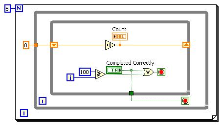
Reset a loop counter and restart the calculation
I have a while loop nested inside a loop for the calculation of a model.
Lets say that I am on the loop for counter 4. Suppose that I wanted to keep track of the number of iterations on a while loop, and if it exceeded a certain 100, exit say number the while loop. I do this to avoid my model of computation being blocked somewhere due to optimization problems. Now, I want to restart the loop counter calculations 4.
Is there a way to do this in labview?
Well first of all, if you want to start the same program inside loop after it got stuck is going not only to get stuck again creating a permanent loop in the code? Would you not just to go and have some sort of identifier as one of the loops is stuck?
But I recommend just nesting your while loop inside an another while loop, and then connect the output to the out-while loop to a variable of the while loop inside, so if optimisation did not appear correctly then it simply repeats the inner while loop.
Although I am of my thoughts that you will end up just straight up in a loop permanent if optimization fails the first time.
-
An associative array, how the records using the loop counter?
In the associative array, how the records using the loop counter? for example
declare
    type population is table of number index by varchar2(64);
    city_population population;
begin
    city_population('Samillve') := 200;
    city_population('Lindenhurst') := 300;

    for i in 1 .. city_population.count
    loop
        dbms_output.put_line(city_population(i)); -- compiler error
    end loop;
end;
/
That would look like
SQL> ed
Wrote file afiedt.buf

  1  declare
  2      type population is table of number index by varchar2(64);
  3      city_population population;
  4      l_index varchar2(64);
  5  begin
  6      city_population('Samillve') := 200;
  7      city_population('Lindenhurst') := 300;
  8      l_index := city_population.first;
  9      while( l_index IS NOT NULL )
 10      loop
 11          dbms_output.put_line(city_population(l_index ));
 12          l_index := city_population.next(l_index);
 13      end loop;
 14* end;
SQL> /
300
200

PL/SQL procedure successfully completed.
Justin
-
1042 q with PXI 8360-controller and maps of Pickering
Hello
I have a 1042 q with a PXI-8360 controller chassis and some maps of Pickering.
Connected to the XP - PC with a PCI-e-card-
Installed is only neither Max nor-PXI, Ni-Visa...
Now the question is how to set up the chassis in the 4.7 or max?
In Max, I see a line with PXI system (unidentified) under "Geräte und interfaces". I tried to load some of the deliverered ini with pxi OR cd files, but I can't control anything.
Can someone me a gibe hint what to do?
I have doenloaded a pickering Web site pipx40vpp.zp file which should cover all my map of pickering a has also a few frontpanles.
But at the start of the frontpanels it says "no card detected". I think I must first of all put in correct place in the max.
Thanks for any help
Thank you very much for the help.
Problem is now solved:
The main problem was that the PCIx1 slot is not working. I put the card in an another PCIx slot and then he worked at the same time.
I found this trick here:
http://digital.NI.com/public.nsf/allkb/05B7131814A5DDA38625710F006BB098?OpenDocument
Try different PCI or PCI Express locations in the host PC for you MXI interface.
The algorithm that use certain BIOS has best behavior in certain time slots than others.Maybe someone will need it in the future.
-
While loop: counter in the name field
Here is the code I have. I tested it and it works on the number one field. (in Formcalc)
if ((FS270Pt1 > = 28,5) and (FS270Pt1 < = 38))
then FS270Pt1.font.fill.color.value = '0,0,0 '.
else FS270Pt1.font.fill.color.value = "255,0,0".
endif
I have 15 number fields should I apply this color to font for the criteria must be respected. I try to use a while statement to achieve this. I know that I have deduced that it should look like this:
var i = 1
While (I < = 15)
do
If ((FS270Pt (i) > = 28.5) and (FS270Pt (i) < = 38))
then FS270Pt (i).font.color.value = "0,0,0".
else FS270Pt (i).font.color.value = "255,0,0".
endif
i = i + 1
endwhile
When I run the 'Script Check syntax' I don't get any errors. However, when running, she says that FS270Pt is unknown. How can I loop through the fields binding name?
It will throw the error. Because the instances of the field to which you refer is not correct. You need to loop through the instances of the field. The domain name is FS270Pt1. So it's instances and be FS270Pt1 [0], FS270Pt1 [1] FS270Pt1 [2]... etc.
Therefore, replace the code inyour
FS270Pt (i) with FS270Pt1 ["+ i +" "]. It should work.
Thank you
Sidonie.
-
In the state machine loop counter
Hi all
I have a state machine, and one State in particular is very busy. I want to State in a loop several times. I thought about that, but I don't like them. Let me know if you have a better idea.
1 Add a registry to offset as a counter for the State. The State will keep looping to himself, while decrementing the counter. If the counter is reset, it will go to the next State. If this isn't the case, it will keep the loop. I don't like this, because I'll have to add a register to offset. If I have a little more State requiring a different number of iteration, I'll have to add a counter for that State. My main VI will be too shift registers.
2. Add a loop around the code in my case for iteration. I do not, because too many wires will be going in and out of the loop. I don't want to do cluster either.
Yik
jyang72211 wrote:
Node of a feedback by counter I need?
Yik
With precision. See this example, each State 5 times before moving earrings. Beats having 5 shift registers and all of these threads passing through other cases.
-
Digital waveforms of SPI with PXI-6552
I am trying to follow the following tutorial about the PXI-6552 module: http://www.ni.com/white-paper/3671/en.
This is the example that I am referring:
You can also use the data Active event to control the relative delay between the response data and the side assets of the sample clock. For example, you can export the active data on PFI 1 event and send it to the PFI 2, which can be configured as the source of Start command acquisition, as shown in Figure 8. You can export the generation of sample DDC CLK clock out and adjust the STROBE acquisition sample clock.
Figure 9 shows a LabVIEW program that configures and outwardly carries the data Active event and the sample clock. The functions marked with an arrow carried out additional system requirements.
Hello MrHappyAsthma,
I'm looking at your code, and I see that you have two sessions of acquisition while the example has an acquisition and sessions of a generation. This could be the reason for the error.
The digital data control are done right click on the front panel, then go on modern > I/O > digital data.
I hope this helps.
-
A problem with delays in call loops and DAQ
I'm programming a simulation for nuclear Rewetting for a reception centre to my company in Switzerland. It is a "fuel rods" heating and then fill the water Chamber. The pump starts automatically as soon as the core of the stem reached 750 C. After that, a requirement that the flow rate be checked to ensure the operation of the pump in the necessary conditions. If not, the heating must be stopped to avoid, well... meltdown. However, we must allow 10 seconds for the pump to respond, while allowing a rate of acquisition of data from 10 to 100 Hz.
The challenge is that I can not add a delay in my other main loop delay all acquisitions, but I can't understand how to trigger a device loop (with data acquisition for the single channel flow control) and the main loop when the loop device determines if the flow a initalised, answering the main loop with the agreement.
I think that a large part of my confusion is in the interaction between loops and knots of default comments labview's willy nilly. The only solution would be to have two 'core' loops that do not communicate with them, but rather to do the same thing while operating different synchronization? Tell me if you want I will post the file (even if its on a unnetworked computer and I don't think that it would also be useful).
Thank you + Curran
Here is a version 9.0.
Maybe you are looking for
-
How can I get firefox/sites Web remember my user name or email address, but not the password?
I want only the user name or your e-mail address remembered.Cookie? But the password still manually typed in
-
The problem seems to be related to Firefox, IE looks ok. Returned to a well known previous restore point did not help. Running Windows 7, FF6.0.2 Java is up to date. Before I did system restore, FF crashes frequently these questions of text entry. Af
-
Pavilion dv1060us: HP SUPPORT ASSISTANT for the XP NOT FUNCTIONING
Just reinstalled Windows XP Pro. I don't get notifications of HP drivers or updates to the BIOS as before. How to reactivate the wizard? I tried the automated on the support site, but it only works with Win7 and beyond.
-
Hi just tried to use the iPad app sweep feature. He found fine document, but when clicking on scan I get an error message ' a problem occurred when scanning, please check your scanner and try again. I have the HP Photosmart Premium C310 series printe
-
BlackBerry Smartphones Recieving duplicate emails, please help!
Hey,. I thought I found how to solve this problem, but I do not think! I had a BlackBerry "BOLD" (never locked) as a gift during a stay in the UNITED Arab Emirates. I recorded for their services and set up my email by phone account (prohibits the com