XY graph: traced by point
Hi my intention is to draw in a XY Chart point by point. Which means for example: I want to draw a diagram of dispersion.
I first check if the array element meets a certain condition (say if it lies between 1 to 5) if I want draw in red, otherwise, I want to check another condition (say between 5-10) and then draw in blue and so on.
First I check the State and link it to a structure of matter as each business structure will contain the corresponding color of conspiracy, but it doesn't seem to work.
Kindly guide me with this.
Thank you!!
Tags: NI Software
Similar Questions
-
XY graph multi plot points and color control live
Hi all
I'm doing something that should be simple, but difficult so far. I had a good look through previous topics and found similar things, but not really what I want.
In my experience, I'm scanning intensity vs. wavelength.
Ideally, I want to be able to:
(1) scan and see live plotted points.
(2) then I want the plot to stay on the graph when I run the following analysis, etc.
(3) I have an arbitrary number of scans. for example to start a scan, I press a button, an arbitrary number of times.
(4) I want to make sure the current analysis is drawn live in (red), and all the previous analyses are drawn in a different color (blue).
(5) sometimes I want can erase the graph of all scans and start over, without having to stop the VI.
Items 1-3 can be supported easily by placing the XY graph building and the XY graphic object inside the loop that runs the scan and uncheck 'clear data on each call' in the properties of graphic generation. See the first VI attached.
However, at the beginning of an analysis, she joined the last part of the previous analysis up to the first point of the next scan.
The difficult parts are 4 and 5.
For article 4, you need to build an array of plots, which is easy if you know the number of plots, but here the number is arbitrary. So, how do I do that? I had a go trying to use Insert table in different ways, but I haven't worked on it. Then if all goes well using the graphics property XY nodes I can adjust the colors of the plots.
For part 5 is not just enough to use the invoke = node reset by default, and have a button that executes the node. This clears the graphic but then when you run the following analysis all parcels previous pop up once again, indicating that the table that stores the plots is not actually deleted. The second accessory shows how I delete the chart.
My biggest problem is point 4 and combining point 4 and 5 together.
Help, please.
I fixed the problem of the route doubly table and added in the desired color, attached plot.
The code now done everything I wanted to in my first post.
No doubt the code could be improved more, but that's for everyone out there who has this problem.
Thanks to tst for give me useful advice.
-
Hi all
I had a program where I read ascii file delimited by tabs, two-colum. The first column contains X values. The second column contains values Y. I would like to build a program that traces on the XY trace and returns the last value. Everything works like a charm except the graph is empty, and I do not understand why. Any help is appreciated.
Thanks in advance,
NSG
Sidelingscroll wrote:
With the plot, I wanted to say that I tried the chart to map out but keep track not only of roll with a single point but grab the computer because it goes through the whole voltammogram that I joined.
Like this, perhaps?

-
Number of points and the number of plots for table and graph
Hi guys,.
Can someone explain to me why I get when I run the number Vi 1 2 plots for each table and graph with 6 points, but when I run vi 2 I get 4 locations with 1 point each run assuming that the same logic applies to two screws
Thank you.
When wiring of the paintings in the graphics, it is assumed that each line are several points of land.
You must convert the 2D table or right-click on the graphic and select "convert table.
-
recording of data points over 6 million deposit
Hello
I try to save all my data points of tension, plus 6 million points, I've gathered using DAQmx LabView functions in a file. The code I did works very well and will be traced all points on a XY graph, but when I try to export field data in a txt or excel file LabView wants to close. I understood how to use the functions of PTM in the toolkit features LabView and it prevents the program from closing; However, it will return a set of data points, but not all the data points. I was wondering if there is a way to divide the data into small amounts and record into several files. I thought maybe I could get my data points index in different table rows and save each line in a clean file but I don't know how fast the program can create and save new files. Any suggestions? My sampling rate is ~ 412 714 per second over a period of 15 seconds and I collect samples total 6 190 708.
Know / do you understand the concept of stream, Central of LabVIEW? A data flow consequences, is that if you have two loops While not connected in series to each other (i.e. you do not have an output of a session at the entrance to the other), they will both run in parallel, 'sharing' of the CPU. So if a loop is the acquisition of data from a DAQ card, which means that if card is programmed to deliver 1000 points to 1 Khz, that loop basically 'wait for' maybe 998 milliseconds, then switch 2 milliseconds delivering 1,000 points (it's probably even faster than that). So, if a loop requires 2 milliseconds per second, which leaves 998 milliseconds per second of time CPU for the loop to do everything he needs to do.
This is the "magic" behind the producer/consumer model. Both loops are connected to their entries by a queue, so that they can operate in parallel. The producer, when he gets his 1000 points, put simply all points on the line and it's done. Points "travel" in the queue (if you want to think about it this way) on to the consumer, where they are removed ("reconstituted") and then plotted, written to the disk, FFT would or whatever during the "copious free time" remaining after the producer had its aliquot.
Bob Schor
-
Delete locations of XY graph at design time
Thanks to LabView 8.6
I inherited several screws maintenance and have met the 'next question' - there are multiple XY graphs, tracing a variety of data and by optimizing things to remove redundant data or unnecessary properties of the XY graph reflect still have 6 slots instead of the 3 that are connected on it. I reduced the caption to include only 3 plots that are actually linked, but properties dialog box still shows 6 locations, both named 'conspiracy 3' and 'Plot 4' and a "V2" Unfortunately duplicate name for what would be the plot 5. Running the VI does not seem to change what contains the properties dialogue box, although it is not all negative effect (within a few seconds of running).
Is there a correct way to remove the plots exist or is - this something where I have to delete the XYGraph and place a new user interface and connect as usual? My biggest concern is that there is a duplicate name that could cause problems at some point, or that this thing is just lose the memory and the CPU cycles and there will not be a problem until the system has worked for 10 hours.
I have attached a picture of the relevant connections (the VI is ridiculously huge and unwieldy to post... don't get started me on the ineffectiveness, it's just that I inherited to maintain), but there isn't really anything unusual here.
All the plots of old who receive more data will not appear, so it is not really so important to remove them. Resize the legend the number of valid locations.
Yet the current situation is not ideal, that's why I posted this idea a long time ago.
 Please vote for him!
 -
Great Multiplot XY graph very slow to update the changes in the line of visibility/colour/width
Hi all
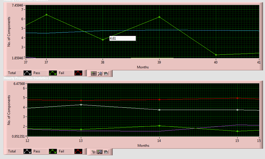
I have a problem that is interesting for you all. I'm trying to update the features of large graph XY (3600 points given for each of the 160 different storylines, all on a graph) by reference and it goes very slowly.
What I've implemented is a system where mousing over other indicators and buttons "will highlight" certain groups of plots by intrigues a thickness of 2 instead of 1. Similarly, clicking on other buttons will change the color of the plot or toggle the visibility of certain parcels. This implementation, I have a Subvi, which contains a reference to the xy graph, and in a loop for each parcel of land for active, applies the changes I want to see done. The problem is that it takes more than a minute to fill in for an update! I'm supposed to be traced new points of every second, and mouseovers and button clicks may occur several times in a second, so it is obviously unacceptable.
I noticed that as I'm a loop in all plots of 160 in the Subvi, the XY graph is updated, one plot at a time. My question is: is it possible to prevent the update until all changes have been made in the chart? Or maybe a way to apply all the changes at the same time, rather than use a loop for?
I discovered that if I simply drag a property node graph xy HUGE and all at once instead of make a loop for, the changes appear immediately as you wish. Is it really what I have to do to get the results I want? It is incredibly long and unmanageable to have a node gigantic property will be all the steps of the loop being applied at the time.
Help is greatly appreciated!
-Aaron
Two things you should consider:
(1) reporter Panel updates. The value True before the loop and false afterwards. Considerably from the things speeds as this place.
(2) no way you can see 3600 points on a graph. With this number of plots, I would consider the decimation of the data in order to reduce the number of items displayed.
-
The point value of graphic display WPF overview
Hello
Y at - it an easy way to display the value of a point (with formatting similar to a slider) flying over when the mouse point? I use the chart control WPF (MStudio 2013) with several plots represented graphic on an AxisDouble. (y-axis) and AxisPrecisionDateTime (x axis). Let me know if you need more information and thanks in advance.
When a
Cursoris set to align the data, it uses theFindNearestValuemethod to find the value of land near. When it is not set to align the data, he reports the value of the current screen with theScreenToDatamethod. The following code example shows how to use both to display the current value of the mouse on a chart using a ToolTip:private static readonly GraphQueryArgs query = new GraphQueryArgs(
PlotsToSearch.Any, SearchDimensions.HorizontalAndVertical,
SearchDirections.ForwardAndReverse, isInclusive: true );public MainWindow( ) {
InitializeComponent( );graph.PlotAreaMouseMove += this.OnPlotAreaMouseMove;
graph.PlotAreaMouseLeave += delegate { graph.ToolTip = null; };
ToolTipService.SetInitialShowDelay( graph, 0 );
ToolTipService.SetShowDuration( graph, int.MaxValue );
}private void OnPlotAreaMouseMove( object sender, MouseEventArgs e ) {
IPlot plot = graph.AllPlots[0];
Point screenPosition = graph.GetPlotAreaPosition( e );
IList pixelValue = graph.ScreenToData( plot, screenPosition );
string tip = string.Format(
"Absolute value at point {0} is {1}.",
screenPosition, FormatValue( pixelValue ) );
Point relativePosition = graph.ScreenToRelative( screenPosition );PlotValue nearestValue = graph.FindNearestValue( plot, relativePosition, query );
if( nearestValue != null )
tip += Environment.NewLine + string.Format(
"Nearest value on {0} is {1}.",
nearestValue.PlotObserver.Label,
FormatValue( nearestValue.Value ) );graph.ToolTip = tip;
}private static string FormatValue( IList values ) {
return string.Join( ", ", values.Cast
} -
Hello
I want to see the values of the graph during mouse pointer points. But sometimes, it does not show values when placed at the points of the graph...
Also when zoomed it shows values in these places where the points on the graph are not present...
So, what will be the changes required in this next vi.
I see the values displayed correctly with zoom. I think you're always to see the rounded question. Change your accuracy on your number two to the fractional chain nodes to 2 instead of 0.
-
I do a simulation for a displacement of the robot vehicle, so I have three exits, where two of them are the coordinates X and Y. So I wanted to take these two outputs to represent them on the X - Y graph so who see the graph is a point moves on the XY graph, drawing a line or curve regardless of the ground until it reached a point selected, the program stops when the condition is met.
My problems are now:
- I try to build the graph and what I have, this is a change in the X and Yscale with the change of my values, but nothing is drawn inside the chart.
- the other thing is that I can not put a desired point fixed on the graph, so when moving plot reaches the desired point the program stops running.
As a note when I active execution of climax, I found the program do what I want, but I can only draw on the graph.
File Untitled is a simple example of what I've done and untitled 1 is a part of my real code.
My guess is that because you're drawn only a single point, the loop runs so fast that you can't follow every point. That's why you can see when you turn on execution highlighting. Add a delay if you want to keep the single window approach. Otherwise, wire a constant false to Reset? entry on the XY build chart and you will be able to see all the points.
PS how in the world you are so blindfolded son.
-
How to adjust the scale of a chart using reference points?
Hello
I'm working on little code to display data from a spectrometer. I've got to the point of producing a graphic intensity vs energy, but I'm having some trouble of calibration of the x-axis (energy).
The customer wants to be able to insert filters with a cutoff of known energy and use those points to determine which positions on the graph correspond to what energies. In terms of programming, I need to let the user click on the graph at two points with known values and use these points to recalculate the XScale multiplier and offset (I think).
I tried a few different things and attached by the best attempt so far. This is a simplified example, but I hope it picks up enough problems to be useful. I can't help thinking there must be an easier way to do it. Any suggestions?
What you have done is good. The only thing that I would have a little problem is that there is no visual feedback on the graph for the user. You can also do this with the sliders. Let them drag the sliders on two points. It is more Visual, and you can see where you have selected. I'm not sure that it will be much easier than what you've done. You could also use a hybrid of the two methods and have the cursor to move until you have selected.
-
AppleScript which rotates all clipping paths in InDesign CS3
At the following link, there is an Applescript script to light all clipping paths and another script to turn everything off. The script to turn off works great.
http://forums.Adobe.com/message/1106200#1106200
I get an error when you try to run the script to enable clipping paths.
Adobe InDesign CS3 has been an error: invalid value for set property 'type of cutting. Planned none / detect the edges/alpha channel/photoshop path/user path of change, but has received (= > ("clippingpath", (cutting type = > traced photoshop, applied path name = > "Path 1"))).
Running InDesign CS3 version 5.0.4
Any ideas on how to solve this problem?
Thank you
The forum ate my post. I would try again.
You cannot use 'all', you must use the name that was used when the path was made. You can find the names by getting "the photoshop clipping paths" of an image.
It works very well here:
Tell application "Adobe InDesign CS3"
Tell document 1
all graphs the value allPics
Repeat with i from 1 to number of allPics
define paths to the names of path of photoshop clipping point of allPics i
If (count elements of paths) > 0 then
{set the Properties of the point i of allPics to {(traced clipping:{{class=fontblue}}applied the name of path:(point 1, path), type of cutting:traced photoshop}}
I allPics Properties of the traced clipping point
end if
end repeat
tell the end
tell the end
-
Match color of series for a table and a chart?
I created a table with 4 sets of data. Then, I created a graphic line with this information. I noticed that when I select the line graph the data in the table becomes highlighted with a lighter version of colors used in the chart. Each series Gets a corresponding really nice color to match the graph. As soon as you select any where else these colors disappear.
Is there a way to automatically match line chart series color color of the card? If this isn't the case, I see this as the colors that appear in the table so that I can put in manually?
Select the series by clicking on the graph, then any "point":
-
How to have a minimum value of 0 by using the graphical editor
Okay, so I thought he did this automatically based on the lowest point, in this case, a line graph. He did it for one of my graphics, but not the other, and I tried everything I could think of to fix this on my own.
I have three charts created at the present time. The first points ranging from 0 to 25, and the axis will display a label value minimum value 0 label and a maximum of 30. So far so good.
The second graph has only points ranging from 25 to 29, and its axis is displays a minimum value of 24 label and the label of the maximum value of 30. Photo below. It's exactly what I want for the third chart as well.

The third diagram has points ranging from 30 to 40, and if by the logic of the second chart, its x axis should show a minimum value label, say, 28 and a maximum of, say, 42. Instead, it ranges from 0-50, as shown below.

Any ideas?
Hi, Honoré,.

Type a value in the Min box.
Kind regards
Ian.
-
WPF graphics, display plot marker (with contact information tooltip) on the mouse event
Hello
I need display the coordinates of the point of the field when the mouse pointer is positioned top/close to him.
I already display a ToolTip with coordinates using the code in this LINK (works equally well for graph).
However, it is not easy to see where the field is selected, especially when you have more than one land close to eachother. Is there a way to display some sort of a 'marker '? A bit of as Signal Analyzer?
Thank you.
If you want to display a target and the label next to the value as a user moves the mouse over a graphic, a possibility would be to use
SetRelativePositionon a slider.If you want to just use a marker in the chart and keep the label in the ToolTip, you can set the relative position of a Visual in the
Childrencollection:XAML
ni:Cursor x:Name="cursor" />
Ellipse x:Name="marker" Width="10" Height="10"
Stroke="Black" StrokeThickness="2"
niPrimitives:RelativePanel.RelativeHorizontalAlignment="Center"
niPrimitives:RelativePanel.RelativeVerticalAlignment="Center"
/>
Code
private void OnPlotAreaMouseMove( object sender, MouseEventArgs e ) {
IPlot plot = graph.AllPlots[0];
Point screenPosition = graph.GetPlotAreaPosition( e );
Point relativePosition = graph.ScreenToRelative( screenPosition );// Option 1
cursor.SetRelativePosition( relativePosition );// Option 2
PlotValue nearestValue = graph.FindNearestValue( plot, relativePosition, query );
if( nearestValue != null ) {
graph.ToolTip = string.Format(
"Nearest value is at ({0},{1}).",
nearestValue.Value.CastPoint nearestValuePosition = nearestValue.GetRelativePosition( );
RelativePanel.SetRelativeHorizontalPosition( marker, nearestValuePosition.X );
RelativePanel.SetRelativeVerticalPosition( marker, nearestValuePosition.Y );
}
}


Maybe you are looking for
-
Hello world I just got a * Toshiba Tecra M2 * who suffers from some strange symptoms. I've first turning on laptop, I got a message saying that the RTC was not working properly. The machine is in storage for 18 months so thought it was enough to be c
-
Slow, slow then inadmissible Macbook Pro
My macbook pro starts to slow down and then pinwheel begins to turn (it comes out and then disappears). If I have the music it starts to skip and when I try force quit programs it takes a long time for the upcoming dialog box upwards and still more t
-
After changing the password in windows server 2003, when the new password take effect?
-
While playing games, etc, the picture is too big for screen
Original title: picture too large for screen a hlp playing games ect photos are too big for the screen EmBee
-
Photosmart 7520 No. Solutions portal / activity report of programs
I just installed my new Photosmart 7520 apparently without problems. It works, BUT when I click on the desktop icon, all that appears are two notebook documents which say basically nothing. I would really like the programs progress that I enjoyed w