XY graph construction
I do a simulation for a displacement of the robot vehicle, so I have three exits, where two of them are the coordinates X and Y. So I wanted to take these two outputs to represent them on the X - Y graph so who see the graph is a point moves on the XY graph, drawing a line or curve regardless of the ground until it reached a point selected, the program stops when the condition is met.
My problems are now:
- I try to build the graph and what I have, this is a change in the X and Yscale with the change of my values, but nothing is drawn inside the chart.
- the other thing is that I can not put a desired point fixed on the graph, so when moving plot reaches the desired point the program stops running.
As a note when I active execution of climax, I found the program do what I want, but I can only draw on the graph.
File Untitled is a simple example of what I've done and untitled 1 is a part of my real code.
My guess is that because you're drawn only a single point, the loop runs so fast that you can't follow every point. That's why you can see when you turn on execution highlighting. Add a delay if you want to keep the single window approach. Otherwise, wire a constant false to Reset? entry on the XY build chart and you will be able to see all the points.
PS how in the world you are so blindfolded son.
Tags: NI Software
Similar Questions
-
The graph refresh is very slow with large data sets
When the graphics of large sets of data in tiara, the construction of the graph is slow (3 pts M takes 30 sec). Fair enough-, the problem is, however, some little change do you later to the curve, it will refresh all over again, and during this time you can't do anything else with DIAdem.
Any way to relieve it?
Problem seems to be solved - restart of DIAdem restored time to update to an acceptable level, or at least it seems that restarting is the only change.
I tried later with the two parameters of charge mentioned by AndreasK and both just as powerful.
I tried remote desktop access and it works all too well - also go remote DIAdem (to see if it's a graphics driver issue)
I feel kind of silly not being able to identify what was wrong and I thank you for your help.
-
How to upgrade a 1 d table multiple graph/diagram of dispersion
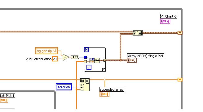
Hi, I am trying to add data to the chart single parcel you see below. It is a 1 d array. When I build another table to add to that, he becomes a 2d array and am not sure how to handle this data in another graph/chart. I have a set x-scale-10 a-100 and at each iteration, about 100 values are inserted there to say-10 and - 20 (x scale) and so on until-100. The chart will be of type point cloud.
Any suggestions?
Hey Grant,
as I said: table of construction is required to create a 2D of your shift register. Change the default constant to a 1 d array!
-
Update graph XY measurement at the same time.
Hello
I want to update chart XY measurement at the same time.
Normally, the graph is last updated after taking the reading.
I tried to make a chart that is updated at the same time, but it's not seems a correct value.
You please guide me.
Thank you very much...
Sorry, I can't know how many plots you have on the chart. Only one?
Here is a small example showing the gradual construction of a xy chart. Maybe you can adapt it to your problem.
-
Tracing data from two locations on the block diagram on the same graph
Hello world
I'm trying to plot data from two distinct processes on a chart. These processes occur in the order.
I have developed several solutions, which none produce the result I want. What I want is for the data to trace in real time each process is running.
The two processes are functionally identical - one loop "for". With each iteration of these loops, data is produced and traced.
The data are plotted in real time, which means that each reference appears on the chart as soon as it is produced.
However, I am not able to get the second process data on the same graph in the same way.
The closest I got combines the graphic with a local variable. This allows the data for the two processes to draw in real time, but the second set of data replaces the first.
I have attached a very simple test VI showing my problem.
Any help with this would be greatly appreciated.
Thank you
You can do something like this. Is the second process just a continuation of the first? If so, it becomes even easier and you can just to keep construction of the table in the second loop.
-
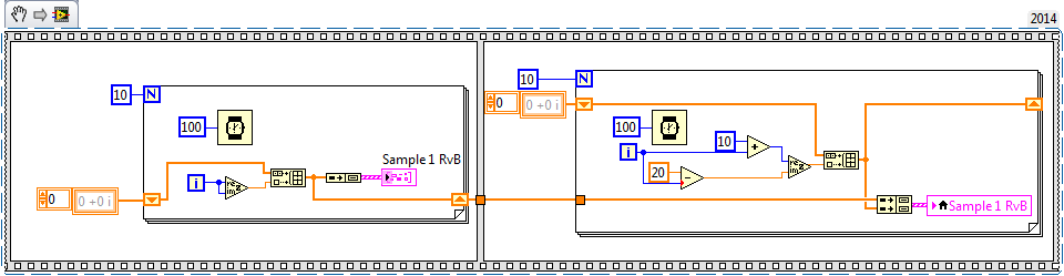
I have a chart single 2D out a conditional of a loop indexing output such that over the rows of the table are not the same size. -Basically, they have different starting and ending points and sizes. -Not so concerned by the endpoints, because as soon as I get correctly starting points, everything shows fall in place.
The challenge is that when I try to have the variable t0 (start time) for each line, the wave of construction vi form would always keep each line at the same starting point.
I used the approach bundled with success (the cluster approach ensures that each waveform starts at different times according to the guidelines of my t0 defined for each line) but then I'm not able to get in the channel names I could make using the graphical approach (wave generation) waveform.
In essence what I get here, I'm losing here.
Because I don't want one of my mentors, Bob and Altenbach have fed up with me I have attached a vi this time

Attached VI shows a combination of the two attempts (first with the waveform graph) and then with the graph of cluster
1. with the first (graphical waveform), I get my channel names as you wish, but the alignment of the wave is not correct.
2. with the second (graphical cluster), the alignment is good, but I can't do the names of channel in the chart, even if they are present in the cluster.
I read some reviews that mentions that attributes can be displayed with waveform and data Dynamics (not clsuters) so I guess that's why.
I saw another report indicating the start time for a waveform 1 d will always remain the same for the rest lines defined for the first line even if changed for the following lines in a loop.
So I guess my question is: what is the way around questions like that?
First of all, let me be the first to the congratulate and thank you for finally posting a code! I'm not 100% certain I understand your question or your code, but I have an idea, perhaps, of what you want to do, so I wrote a little VI who made something simple that could be relevant.
You mention waveforms of different lengths and beginning at different times. You also want everyone to have a unique attribute (although I'm not sure what you want to do with the attribute). So, I did the following:
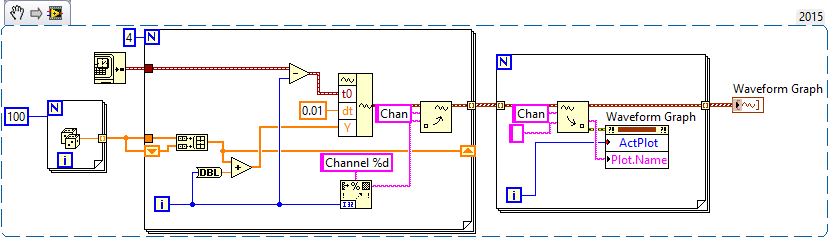
- Generated an array of 100-sample random to represent one second of a waveform.
- Created 4 waveforms on this 100-sample basis. The first waveform (channel 0) is just these 100 points. The second, 1 channel, is the concatenation of string 0 with the base of 100 samples, or a waveform "double". Channel 2 is 1 string concatenated with the base, and channel 3 is 2 string concatenated with the base.
- In order to trace the four channels that they rest 'on' the other, the waveform has the number of the channel added to it. Channel 3 is 3 + (4 copies of the basis of 100 points), a waveform 400-point random centered around a shift of 3.
- All channels have dt value 0.01 (but I guess I could have varied, as well).
- To make the channels start at different times, I started channel N N seconds before channel 0 (by subtracting the index of the loop, I, T0).
- For each channel, I created an attribute called "Chan" equal to "Channel N" (where N = 0, 1, 2 or 3, as the case may be).
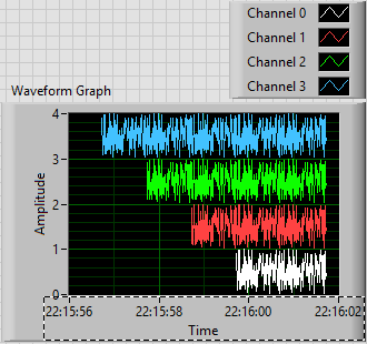
This is the plot that results. Scale X is the absolute time value (no Date) using the 24-hour HH: mm
 S format. You can see that the plots are 1, 2, 3 and 4 seconds of time, and are offset from each other by a second. I used the trace attributes to change the name to the respective attribute.
The code to do this is very simple - I almost don't need to show it, because I think it is completely described by the text above, but this is here:
Now, it was not that much faster that some of your previous posts, when you refused to your postcode, "guess us" what you wanted (but not to not correctly guess), you tried to "push" us in the right direction (still refuses to post code), and no one seemed very happy?
Bob Schor
-
the power of the spectrum graph and butterworth filter
Hello
I am beginner in labview, I want to see the power spectrum of the sound samples, I want to see if there is any reason in these samples.
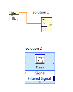
I use spectral measure, and then I filtered with butterworth filter samples. For output I using waveform graphs.
Before filtering the signal, I'm in the x axis of the graph between 0-22500 and the data mostly in 0-2500.
I've tried to filter using these values (fs = 1000 Hz, 0.125 hz = fl and fh = 500 hz) and the graphics almost the same thing but the axis of the graph is between 0-0, 5.
issues related to the:
What is the x axis properties? Why is different, but the graphics are the same?
Make the mistake with the program?
Hi Limavolt,
You have a problem with the bandpass filter VI, this VI generates only the signal of value i.e. table DBL. The signal is a cluster.
solution 1: you need to calculate 'dt' using the sampling frequency and use VI waveform construction to generate a signal's own scaling.
Normally, dt = sampling frequency/No. samples
Solution 2: replace the VI butterworth filter with filter VI express, this will produce signal without scaling.
-
XY graph & remove erase old data
Hi there-
I have a XY chart that receives the time from the beginning (x) and temperature (y) at user-defined intervals (say, 5 seconds). The graph begins plotting when a 'Start' button is pressed and stops when the user presses the button "Stop". [I know, creative how!] There is a loop that monitors the status of the buttons and then another loop in parallel which adds the current reading to the XY graph using Express construction graph XY ('reset' is set to FALSE), and it uses 'Elapsed Time' to space the data points.
When the VI is on, I would like the user to be able to start and stop several times. This means that the XY graph must be reset. I tried a few methods, but they clear only temporarily, and then when the next point is traced, the former items reappear.
I looked everywhere for a solution to this, but have not been able to find one. I tried the reset by default, writes an empty array to the curve, sending NaN to x and y in the definition of "reset" to TRUE, and a few other variants. [I got an idea: is there a way to erase all the memory associated with a graph?]
My code would be much too complicated to post, so I hope you can help me with my description only.
Quevvy wrote:
I use the Express VI 'Building XY Graph' and uses the entry "reset". But I want to reset before you add the first data point and then back to no adjustment so that all points can be plotted.I am downloading an idea of how I emptied the graph and how the graph turned after the start and stop it twice.

Picture of you is meaningless. The data are stored in the express VI, sending a whiteboard directly to a property of the graph node will not do something useful.
To make sure that the reset button goes back to FALSE after it has been read by the code, you should lock the action.
Have you tried my example above?
Your data seems to go back in time. It's interesting

-
Create horizontal lines on a graph
I'm looking to create horizontal lines on my paintings of waveform. I know that I can't use the cursors on a chart, but I want to find a way to draw lines on the y-axis of a graph (chart) of a control on my front. The reason is: I am in a position a sinusoidal signal that changes in amplitude due to the deformation of a material. I need to adjust the length of these horizontal lines using as reference.
I understand that I could use the limits of the curve because of it, but then I wouldn't be able to tell how long out of bounds, I. I am a super novice to Labview and you guys have been such a great help with all my endeavorsso far. Any suggestions?
Draw several lines in the table, where two of the parcels are borders. I don't remember the exact requirements, but you can probably do it by grouping the values or the construction of a table. Check the contextual help and the examples in the table.
-
graph timestampo digital and analog mixed
Hola:
Estoy acquired a series of canales analogicos y digitales. MI intention, are representarlos in the grafica (graphic Mixed Signal) misma, pero no encuentro the respond. Editor United Nations VI con lo me gustaria realize.
MUCHAS gracias.
Hello:
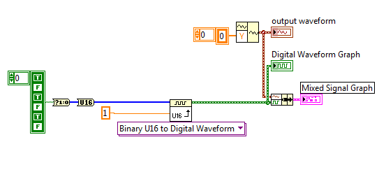
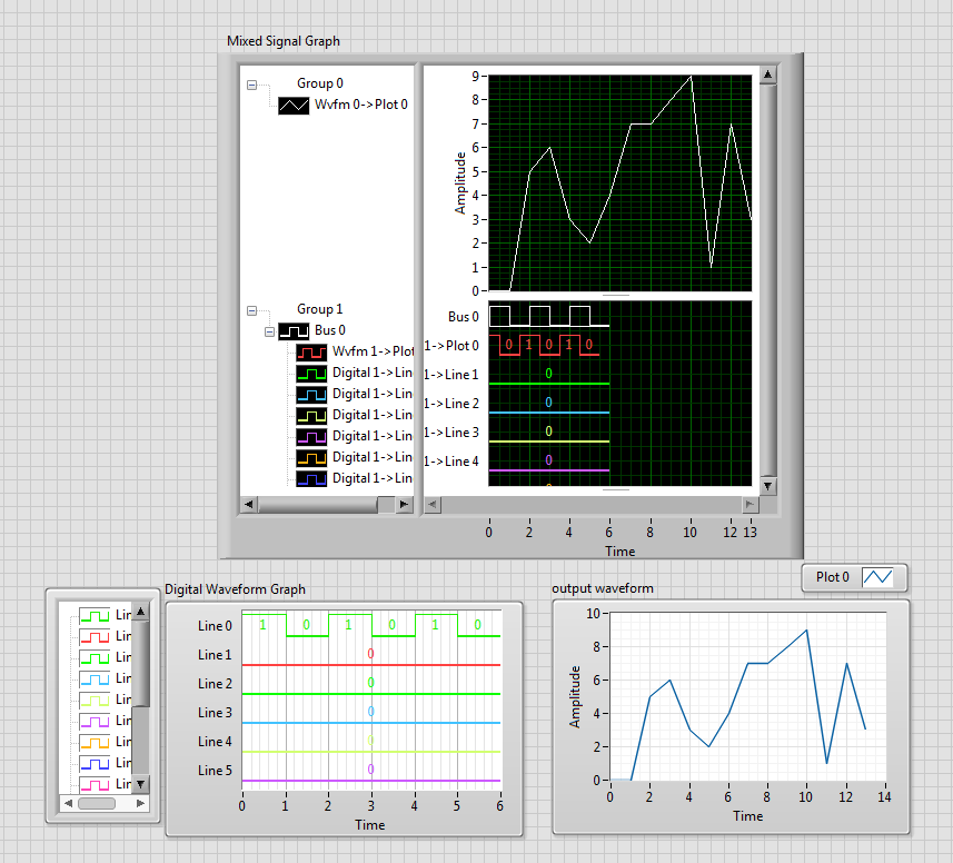
I'm acquiring a number of analog and digital channels. I represent the two channels on the same graph (Mixed graphic Signal), but can not find the solution. Joined a VI with what I have.
Thank you very much.
Hi, Carlos
You can implement architecture below, this converts the array to a waveform. Of course if you were after a specific time stamp, then you can use the wave function of construction as well as the function of generation of digital signals. But this should show the basic principle of what you need to see.
See you soon
J
-
Multi-terrain graphs, is there a better way?
I'm still not good at graphics in LabView, but I think I do a few programs and I can usually get a graph to show with what I want to show him only a few hours of dinking with it autour...
In any case using graphics certainly made for messy code unless there is a better way to this thread. Basically, this chart shows the four temperature sensors and is updated every minute. A check of stabilization is carried out every 15 minutes. Apparently the only way I could get the multiple locations with time that x-axis it are use an xy graph, but I have my reading on the index individually and each put in it is the own shift register and add it to the chart separately.
There must be a better way?
I think that part of your problem is that you are not aware of the option 'Concatenate entries"to build array. You don't need several bays to build the set of clusters, we made connections in graph (pink wire). Just expand the build, wire all clusters, then right-click on the picture of construction and choose 'Concatenate entries. Then, you can use a cluster to store all your berries to graph (orange wire) which will be greatly cleans your diagram.
-
change the dt on a waveform graph
Hey guys,.
Im trying to create a graphical representation of the temperature over time, currently using a graph in the form of wave. I want the user to be able to select the interval that the temperature reading is held and the level which is considered to be a noteworthy event. I have the level and random data by plotting the curve on the same graph, which is a start, now I'm trying to get the interval between readings to reflect in the axis of the x.
I see the graphic waveform always incriments by any reading, this works very well if the measurement interval is one second, but if the user selects 2 seconds I want the next value on the x axis for incriment by two.
I found something that has a value of Y and a value of dt (waveform of the construction), I'm sure that im using wrong by sending a single value at a time. is there a way to do what I want to do?
Ill post a screenshot of what I have, thanks for any help
Ben wrote:
-
Hi, I tried to graph of the entire greater function Grapher. However, I discovered that I can't put 'int' as a valid command.

Here is the image that shows what it looks like on calculator TI-84.

So, I was wondering if there is another symbol that can replace "int" to Grapher?
Enjoy it!
Use Floor. In other cases, click Help, and then view the built-in definitions.
(144660)
-
Firefox does not (Cup) of the lower edge and the right edge of the graph. IE10 does not work.
Firefox does not (Cup) of the lower edge and the right edge of the graph. IE10 does not work.
Office Windows 7 2009 service pack 1 Firefox 26 Internet Explorer 10
Flash player version 11.9.900.170 plugin 11.9.900.170 activex version used by FirefoxProblem began late November when Miniclip.com forced updated flash player to version above
-C' was when they started to play a video advertising in the game box before you could start.Have screen shots of IE10 and Firefox26 side-by-side clearly showing the problem - how these can be downloaded for see you? E-mail? Web site? This place seems to be text only?
In the meanwhile the grandchildren and self have learned to use IE10 instead of Firefox that we prefer.
Their House of Windows XP has same Flash Player in Firefox and it works fine.Downloaded two screenshots on Media Gallery.
You can not attach a screenshot in the first row who starts a thread, but you can do it in subsequent responses.
Try disabling hardware acceleration in Firefox (you will need to close and restart Firefox).
- Tools > Options > advanced > General > Browsing: "use hardware acceleration when available.
See also:
Reset the zoom of page on pages that are causing problems.
- View > Zoom > reset (Ctrl + 0 (zero); 0 + Command on Mac)
-
Of a complete log of Information can I find myself with several graphs of selected information
I received a great response here before, here's something that I'm not sure is possible... but maybe you know.
Current version of numbers (3.6.1)
So, I create a log of the different courses. Here is a simplified version of what I do:

The idea is so that I will have separate sheets for each of the classes, where I will have the analysis of numbers. For example:

What I would like to have on this page is a graph being each class, day by day, showing the presence so that I can follow increases or decreases trends, from the newspaper on the first sheet.
I thought I'd try to find a way to have a referenced version (Alias) of the main newspaper on this sheet, which I can then do a filter before you apply a graphic, or perhaps a function which will only list info in a new table which matches certain information (such as the title of "Workshop").
I can be looking for a function that does not exist, but if there is anywhere I could get a clear answer on this subject, I figure that it would be here. Thanks for any advice you can give.
Kevin Cunningham wrote:
I can be looking for a function that does not exist, but if there is anywhere I could get a clear answer about it,
Numbers (and other spreadsheets) are good to extract summaries of data and plot summary. Here's a way, using SUMIFS.

The formula in B2, filled to the bottom of the column:
= SUMIFS(log::E,log::$B,$a2,log::$C,$A$1)
The formula in C2, filled to the bottom of the column:
= IFERROR (SUMIFS(log::F,log::$B,$a2,log::$C,$A$1) "/ B2," "")
The SIERREUR function tells number of leave the empty cell if there is an error because attendance is 0.
The graph is 2D 2 axes in the case where you want to do something similar.
Once you have the summary table and table of work, then you can 'clone' them by copy - paste other sheets and put another name of the workshop in cell A1.
SG


Maybe you are looking for
-
My air ipad storage is almost full. How do I purge of the less important items? Y at - it app to serve the music and pictures in double? How can I keep on my ipad apps that are shared by other devices?
-
I get a message that my Firefox is months our date. I don't see what version I have in respect of the aid. But he updated not so long ago. Maybe weeks.
-
I tried to put the BBC News page as my homepage, but every time I start I see the page of Google. I tried dragging the icon of the BBC (on the line of the BBC URL) on the Home icon on the far right of the screen and saw a message ' do you want this d
-
Why windows live Director has no timeline functionality?
This makes it extremely difficult/impossible to produce separate audio / subtitles for your videos
-
Ive got a question for Windows Vista Home Premium? Please read.
When I bought a computer 2 years ago, is it came with Windows Vista Home Premium reinstall cd. The computer that comes with it is a gateway Gt5411E and im wondering if the installation cd will work on a new build machine what im doing right now. Than