Y axis on table
Hi all
I made a table that has four series, I want to know if the first series will use the left axis, and the second series will be user axis Y on the right? And how about the series third and fourth series?
For example,.
The fourth series (0.30% at the bottom), I want it to use the right axis Y not left, how can I do this? I want the chart to look like photo 2. Thank you very much!
https://Apex.Oracle.com/pls/Apex/f?p=52890:6:17207070338513:
WORKSPACE: JINZHI02
username:[email protected]
password: test
(photo 1)

Photo 2

Hi jane.kuang,
Jane.Kuang wrote:
I made a table that has four series, I want to know if the first series will use the left axis, and the second series will be user axis Y on the right? And how about the series third and fourth series?
For example,.
The fourth series (0.30% at the bottom), I want it to use the right axis Y not left, how can I do this? I want the chart to look like photo 2. Thank you very much!
You will need to create custom for your chart XML data and specify which series should be mapped with which axis Y.
Hilary Farell has set up an example for several graphic value here axes: https://apex.oracle.com/pls/apex/f?p=36648:7:17434503206424:NO:
Kind regards
Kiran
Tags: Database
Similar Questions
-
How to trace mutiple tables on the left and right value axes?
Hello world
I have a problem (I hope that little?) ... I have a chart 2D with 6 columns of data that I need to plot a graph... I would like to 0 on the left axis and tables 1 to 5 draw using the left axis... I tried using clusters to group the two sets of data connected to a loop for each axis. But it does not work... Can't seem to find anything online to help with this...
Any suggestions would be greatly appreciated.
Kind regards
Jack
Do not worry... Found this link...
http://digital.NI.com/public.nsf/allkb/049C7E362BE4270A8625756E005CC46F
Thanks for vewing...
Kind regards
Jack
-
Graphical waveform reference conflict with table 2D?
Hello world
I have a problem (I hope so easy?) with the joint 2.vi Untiltted... I need to wire a reference (with the chart "MVC and Stim") to the Sub - VI X axis Curs table under so I get the x-axis positions the cursor over the chart MVC and Stim... When this chart is a 1 d array, it works fine (graph at the bottom should graphic data between the sliders)... But I change the MVC and graphic stem in a 2D array that draws multiple waveforms graph Ref do not connect to the Subvi?
Any suggestions? I'm on a tight schedule, and it's killing me slowly...
Kind regards
Jack
Hello
I do not have chekced your screws I did not LabVIEW on my pc at the moment. I hope that the code is LV 2010 or below. If this isn't the case, please send the code in a version compatible with LV 2010.
However, a few questions:
What is your Ref entry selected to include the data type? You create the reference control once again inside your sub vi when you changed from 1 d in table 2D graphics?
If Yes, suggest to the two qus, try removing the data type "include". This can cause problems in the future. Otherwise, you must re-create your sub vi entry ref control again.
one way is, just transfer the reference on the front of the vi that has graphics for the sub vi, use application of the nodes to get the name of the control and the reference in the Panel, check your "MVC" and "Stim" among the control names, get the control reference. This will save you the dotted arrows.
-
Guy g ' Day,.
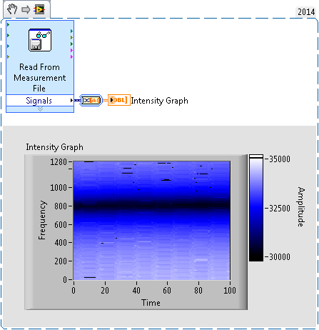
I have a table 2D inlcuding values for a 3D-Graph Surface.
I want to get a 2D image where ist die axis z interpreted by color.
I tried my own, but could not get the good conversion between the z and a color.
I suggest I have likely values (range 30000-35000). No doubt LabView trying to interpretate the value directly as a color code.
The image itself has for good size (1280 * 100).
The upper graph shows the 3D-Graph, powered with the same information.
Any suggestions how to get the right image?
Thank you

-
How can I set the time axis on my waveform table to show run time that is to say whenever I start the program I should have 0 as the starting point. I've been messing around with the without success. I'm under Labview 2012.
Thank you!
Townes wrote:
I can't understand what you mean. I have no formal training with labview. It took me a long time to write the simple program that I joined. Any guidance would be greatly appreciated!
Its pretty normal for a beginner to take the time to write code. Right-click the map of waveform > Create > property node > historical data, you will get a property node, keep this at the beginning of the code and create a constant. You can also go to the VI properties and > run and select "clear indicators when it is called.
I recommend you to go through the basic materials of LabVIEW which will give you an understanding on the basics of bases/components of LabVIEW.
-
In the column of table when the values are grater that maximum linear axis it does not show the bar
Hi guys,.
In the column of table when the values are grater than there maximum linear axis it does not show the Bar.But I want to display the bar up to the maximum limit of the axis is linear without changing the limit max.
Consider following the example:
The values are 80 90 200 300
and here is the result:
Left: when I don't put maximum property of linear axis.
Right: when I put in maximum property of linear axis to 200.

Law 4th bar is not visible because the value of this bar is 300 which is excedding maxium. But I want the 4th bar to appear identical to 3 bar.
How can I do this?
Thanks in advance.
Then you should change the value of Y to the maximum value.
Another option, you should consider is changing the Render item column to reflect that the value is greater than the specified maximum value.
-
Table axis range error labview
Hello
I'm trying to programmatically set the chart to display a minute 30 or 60 minute range. I can do this by setting the following in a case manager properties, if the user presses a button to apply the settings of the map (with the display of absolute time format):
Entry: graph time = 30 minutes or 60 minutes
Properties (in order):
Scalefit value of 0 (no autoscale)
Offset of the value timestamp 'get the current time.
Startrange value timestamp 'get the current time.
Multiplier to 1 /(1000 Samples)
Minimum for the timestamp 'get the current time.
Maximum to 'Get the current time' + 1800s (for table duration = 30)
Loosefit set to true
Result:
While I can get the output offset table correctly, the time slot is always set to 40 minutes.
I ask these same settings in the table more away in the loop and the min, max values are completely different - one offset is consistent.
Here is a sample run: table length = 60,.
Minimum = 15:01 25 January 2013
Maximum = 16:01, 25 January 2013
Offset = Minimum
Output:
Minimum = 15:02 January 25, 2013
Maximum = 15:42 25 January 2013
Offset = 15:01 25 January 2013
I am confused because I have not set these properties of chart in my code otherwise. No idea where they come from? One solution is to take the code in the case manager, but I would like to refrain to do so because it uses more memory. Thank you!
Could you post an excerpt of our VI? It would be very useful.
Right on the top of my head, I think you may have a problem with the amount of data in the table and affecting the size. You may also need to set the length of the history of the chart.
You might be better off using a graph of waveform instead of graph. It is much easier to control the data in a chart as you define explicitly all the data instead of letting the LV to annex all automatically.
-
drop table left-right scale of the value axis are not the same scale
http://img20.imageshack.us/img20/6264/questionk.PNG
the scale of the axis left and right are not the same.
How to configure?
Thank you very much!Hello
Try this
Chart, Goto Advanced properties-> check the line sync and the axis of the bar
This will make the two scale of identical values.Thank you
Vino -
Pivot table dynamic table - chart axis of the show as "percent".
Hi all
I have a pivot table is generated, with the lines as year/month and columns like web browser. However I only watch 5 albums used, browsers so that used columns are dynamic.
I would like to show the graph as a 'percentage of line. I know that I can turn this on the data in the table, but it does not filter although in the graph. Does anyone know how to get there? Can you add the total of a line and use it in a formula?
Thanks in advanceHello
Not sure how the PivotTable, however we have may be able to pull this back as a separate column in the criteria tab which you can then use.
What is your metric name?Lets say you have Time.YearMonth, browser, count
Add another column, change the fx for this column and use sum (time.yearmonth County) - this will give you the total amount for the year regardless of browser.
Add another column and simply count / sum (time.yearmonth County) * 100 to get the percentage of the total for the year - plays about with using them in the pivot or you might get away with a straight table view?Hope this helps, another solution would be to implement a shaved basic measure to the RPD.
Published by: Alastair_PeakIndicators on March 31, 2010 08:26
-
Hi all
I have a report that has a chart, the x-axis has quarter details... but I need to put them in ascending order of quarters... as q1 2008 q2 2008 Q3 2008 Q4 2008 Q1 2009... etc.
I am not able to make this change using the existing properties? Can someone suggest a solution
Thank you
Natrajtry a thing. in step 1 of the design of your report, set the order of the field quarter to ASC and then generate your graph
-
How to trace datetime against temperature table of waveform
Hi guys,.
I try to draw data from my table and to draw a time value date on the x axis and the value of the temperature which resemble 32.5 c
on the y axis on a cat of waveform. I'm new to studio measure, anyone have an example on how to proceed?
I have a loop that loop and gets the data from each row (time and temperature) and I want to draw in each loop, I leave,
If the graph will be a building, and the user can see until I read all the records.
Hi lil_racoon,
Thank you for the additional information. After looking at what you're trying to do, I think that the enclosed code will achieve your goal. Try to adapt it to the work of your application.
Thank you
-
change the properties of the report axis (together begin and end)
Hey everybody,
I am a beginner with DIAdem reports and close to despair that I have yet found any solution.
I wrote a script, which produces reports of various measures with 9 pages (3 2D-slots each, a total of 27 lots).
Now, I want to put the beginning and the end of the x-axis of certain specific parcels.
First question: tiara offers something similar to an Object Explorer (for easy access to the names of the objects drawn in a report)?
I created two GlobalDims called x_time_begin and x_time_end to set these properties, but I don't know how to access these variables in the report (tried @... @ and @... @ the 'Axis settings' tab).
These variables change for each measure, so each report has a different set.
The presentation of the State is responsible from a set of. TDMS files and is not altered in the script.
How can I find the name of a specific plot in the report can access?
Is it possible to define the range of the x-axis in a variable at all?
Best regards
Nils
Hi Nils,
It is possible to set the x-axis of begging and positions in the scripts end (see text below). When you create a report object in the script you can name it anything you want to access later. Otherwise, I think that the default name is the name of the object, of the number (for example the 2D first table is called "2DTable1")
Dim oMy2DAxisSystem, oMyXScaling

Report.NewLayout

Set oMy2DAxisSystem = Report.ActiveSheet.Objects.Add (eReportObject2DAxisSystem, "My2DAxisSystem")

Set oMyXScaling = oMy2DAxisSystem.XAxis.Scaling

oMyXScaling.AutoScalingType = eAxisAutoScalingManual

oMyXScaling.Begin = 0.01

oMyXScaling.End = 100
Hope that helps,
Sadie
-
Vertical sync to the temporal position of two or more systems 2D axis?
Tiara in: REVIEWS,.
Is it possible to vertically sync the time position of two or more cards of 2D axis system placed over the other?
I have posted several channels on a 2D graph and a channel of particular interest on a separate table above, that was very easy to do. It would really help synchronize time on the two charts position, such as a scrolling graph also scrolls the second table, or zoom graph also zooms in the second picture of the same area, which seems to be a pretty basic thing you want to do, but I have not found a way to do it again.
Any help is greatly appreciated!
JohnGrove salvation,
Actually, yes we CAN do it-if you have DIAdem 2010. There is an example called "Alignment of the functions in DIAdem VIEW" delivered for the first time with DIAdem 2010. When you run this example, you will get a new Star ' * ' icon in the top right corner of the Panel VIEW. Click on the new icon for a collection of functions of alignment axis which I think will make you happy.
Let us know,
Brad Turpin
Tiara Product Support Engineer
National Instruments
-
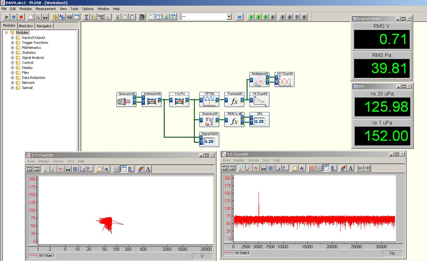
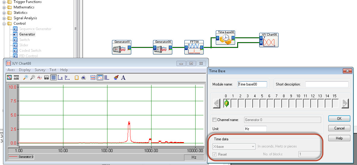
FFT to display with newspaper frequency axis
Hello
I'm trying to get my fft to display frequency (x axis) with a logarithmic scale.
There is no option for this in the table y/t
The xy graph has possibility of HRT, but I cannot "demux" the fft output signal successfully.
I use DasyLab 12.
Someone at - it ideas?
Thank you
Matt
Use the time Base module (special offer) to extract the x axis out of the block of the FFT.
-
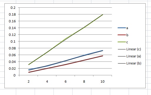
How to convert a table to graph XY?
Hello
I'm new to LabVIEW. For my course, I have to create a graph of load on a beam against the measured voltage to a rosette strain gage.
I managed to create the required table and I can export to Microsoft Excel to create the chart, and that works fine. However, ideally, I would just use LabVIEW to create the chart.
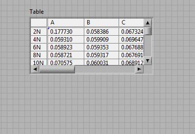
Attached is an example of the table after the test is run. [table 1]
in this table, I need to draw 3 lines (A, B, C) on a single graph of voltage(y-axis) against load(x-axis), with a line of regression for each of them.
Also attached, it is an example of the chart created in excel, to give an idea of what I'm trying to create. [Chart1]
Any help would be appreciated, as I am new on using Labview.
Thank you
I managed to understand what I had done wrong. I was just posting this when you posted your reply Ian.
Ian and Bjorn thanks for both of your help. It is much appreciated
Luke

Maybe you are looking for
-
How do I change the original HARD disk and apply SSDS, which she can. Milan
-
Hello Sir / Madam,. Have we not to have a separate server of our own to do a push request. Please help me about what I am a newbie to the blackberry development. Kind regards Sandesh.
-
As in the question. Windows 7 x 64 'preconfigured search folders' for 10-20 minutes after pluging base peripheral USB - flash stick, mouse, keyboard. The installation of the drivers is displayed. The small circles looking for minutes and minutes. The
-
Limiting full blackBerry Smartphones BlackBerry group
BB users Can someone help here... it's pretty frustrating I created a group and now at 30 members it already says WARNING FULL non-member can be added 1. What is the work around 2. is it a problem with the service provider or RIM OS Any clue? Thanks
-
Hello, after being forced to reformat my Mac, afterwards I reinstall the creativ cloud pour installer I my adobe software, adobe 19th monthly subscription, and I was charged January 7, 2016, Lun ID works, but confirms to me that I don't have any subs