4071 DMM auto range
Hello
I am trying to develop resistance to 4-wire mode of auto range with a FlexDMM 4071 (5.5 digit) then change the range to the correct value to acquire a 7.5 figures measure. However I can't find a vi that sets the range of 4071 as AUTO?
Thanks for any ideas
N
Set the range to-1.
Definition of the beach-1 light autorange
-2 disables autorange it
-3 affect both autorange
See here for more information:http://zone.ni.com/reference/en-XX/help/370384N-01/dmmviref/nidmm_config_measurement/
Tags: NI Hardware
Similar Questions
-
Hi again,
I have another question regarding the 4071 dmm and autorange. When you use the selector/DMM express it is not possible to select autorange and 7.5 figures? Is there a limitation in this sense?
Thanks again,
Concerning
Hi Nitad,
By default, the automatic selection is set to a resolution of 5 1/2 digits and can not be changed in the Express vi. However, the automatic adaptation to 7 1/2 digit can be accomplished by manually configuring the DMM for the settings of 7 1/2 numbers in the DMM measurement by default using DMM. You will need to use the lower level (instead of the Express VI) screw to set up your measurements for 7 1/2 digit. For reference, I've listed 7 settings 1/2 digits, you need to set up explicitly.
Opening time: 100 ms
Auto zero: on
ADC Cal: on
Rejection of DC of nose: strong weight
Number of averages: 4
You can look through the viewfinder of the example to find an example that would be a good starting point to change your code to auto-gamme to 7 1/2 digit. In the example Finder folder, I would use the example in: material input and output--> modular instruments and devices--> NOR-DMM (digital multimeters)--> measures only--> resistance measurement (2 or 4-wire) .vi.
When you use 7 1/2 digit in the automatic selection, your total measurement time will be long. Each measured range is 7 1/2 digit, so when the DMM will analyze different ranges to find the optimum range, the total time can be long fast.
Cheers!
Brandon G
-
The specifications for the PXI-4071 DMM indicate the input resistance can be chosen as 10 MOhm, 10 GOhm of the 100 mV 1 V and 10 V ranges. I see where it can be entered on the soft dashboard, but I could not find how to set up the input resistance when you use the DMM in a VI. Suggestions?
Thank you!
The f
You must use a property node.

-
Help with niSwitch example of DMM switch Handshaking
I have a bit of trouble getting my stint of PXI-2575 multiplexer and PXI-4071 DMM talking to each other. "" They are located in a PXI-1045 chassis on which I am currently running the "niSwitch DMM Handshaking.vi switch ' example.
At the moment all I'm doing is read in a DC using this example.
SWITCH
Topology: 2575/1fil 196 x 1 Mux
List of Scan: ch0-> com;
Trigger entry: front connector
Advanced analysis of output: front connector
DMM
Type of measure: Volts DC
[...]
The destination full measure: external
Source of relaxation: external
Then try to run the VI, I get the following error:
Possible reasons:
Driver status: (Hex 0xBFFA6B9F) DAQmx 89120 error has occurred:
Terminal of source routing is not found on the device.Make sure that the name of the terminal is valid for the specified device. See Measurement & Automation explore valid names of terminals.
Property: DAQmx_DigEdge_AdvTrig_Src
Property: DAQmx_DigEdge_AdvTrig_Edge
Source device: PXI1Slot7
Terminal of source: TrigInStatus code :-89120
Of course, I'm new to this. Help, please!
Thank you.
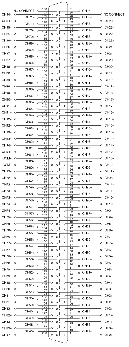
Hey Sean,
Looks like we have a differential of 2 volts. We will use 2 wires 98 x 1 and the following connections:
The help of switches:
On this basis, we can see in the lower right that CH0 + is pin 1 and CH0 - pin 2. We need to hang the signal of 2 volts at pin 1 and pin 2 land.
We hang the DMM HI COM + (PIN NUMBER 173) and the DMM Lo-COM (PIN 174).
Now all we have to do is open switch Soft blanks Panel ('start' programs' National Instruments' OR-Switch), select topology (98 x 1 2 son) and connect CH0 to Com. If we take a DMM measure, we should now read 2 volts.
Now that we have all this work, we will make it faster by using the example of transfer protocol you mentioned previously:
Suppose we want to connect channel 0 to com, take a measure, then connect the way com 1, take a measure, and then connect track 2 com, etc. all the way up to channel 15 to com. A scan list that performs this operation is: "ch0-> com; CH1-> com; CH2-> com; Ch3-> com; CH4-> com; CH5-> com; CH6-> com; CH7-> com; CH8-> com; CH9-> com; Ch10-> com; CH11-> com; Ch12-> com; ch13-> com; CH14-> com; CH15-> com; ».
We can simplify this scan to help list of ':', the following: ch0:15-> com This is equivalent to the same actions as above, but is much easier to watch. I hope this is enough information to get started. Let us know if you have any questions. Have a great day!
-
I tried to change the name of the PXI-4071 "DMM" that worked, but when I try to launch the "self-test" or open the app it Panel always fails. This is also true if I pass the new name of the ivi driver. Return to the name "PXI-4071" makes everything works again. Note I managed to change the name of our PXI-2530 b 'SWITCH' and the name of our SMU-6363 to "MIO" and I could pass these names to their IVI drivers and they would work.
I messed with alias VISA, IVI logical names, but nothing works unless it is called "PXI-4071.
-
I have requirment to test the MEASURMENT FULL port trigger pin in NI 4071 DMM
someone can help me with the behavior of the PIN and how can we test that?
Thanks adavance
IVI
Hello
Maybe it's what you're looking for
http://zone.NI.com/reference/en-XX/help/370384N-01/DMM/generating_measurement_complete/
See you soon
GAPO
-
How to acquire data through several channels in parallel using E 6070 PXI, PXI-4071 and LabVIEW?
Hello
I use LabVIEW and NI PXI-4071 PXI NOR 6070E to measure the current through a variable resistance. Now, I use a single channel of SCB - 68, but I want to add another channel at the same time so that I can have two resistors instead of one that I cam measure current through them.
I have attached a Pdf file showing installation of equipment to use and code LabVIEW also.
Can someone look at these files and give me some guidelines or ideas that can help me solve this problem, please.
Thanks in advance.
Best regards
Shaheen.
Your 4071 can do a measure at a time. Your data acquisition cannot measure resistance is not she of the analog inputs.
However, you could use a multiplexer and multiplexer your 4071 DMM. This habit give you simultaneous action, but can acquire data one after the other, the speed depends on the multiplexer, you choose!
I hope this helps.
-
TIMESTAMP (6) partitioned key-> range partitioned table ddl needed
What is the DDL TIMESTAMP syntax (6) partitioned key, range partitioned table
Published by: oracletune on January 11, 2013 10:26>
What is the DDL TIMESTAMP syntax (6) partitioned key, range partitioned table
>
Don't know what you're asking. Are you asking how to create a table partitioned using a TIMESTAMP column (6) for the key?CREATE TABLE TEST1 ( USERID NUMBER, ENTRYCREATEDDATE TIMESTAMP(6) ) PARTITION BY RANGE (ENTRYCREATEDDATE) INTERVAL(NUMTOYMINTERVAL(1, 'MONTH')) ( PARTITION P0 VALUES LESS THAN (TO_DATE('1-1-2013', 'DD-MM-YYYY')) )See my answer posted: January 10, 2013 21:56 if you need to do on a TIMESTAMP with TIME ZONE column. You must add a virtual column.
Creating scores of auto range -
Adjust the auto-attack for all paragraphs
Hi-
I want to increase my auto ranging from 115 to 125% for all "normal" paragraphs in my document.
I know that I usually have to apply the paragraph style for those I want changed, but this document has hundreds of points, I can't do it manually.
I read in another post that the trick is to change the standard paragraph style and then have it as a point of departure for those I want to change.
I did, but it does not affect anything other than paragraphs that apply styles to manually.
What can I do? Lars
Auto leader amaount is defined in paragraph style definition in the Justification section. If you have changed manually for some paragraphs is probably now a local replacement option that needs to be removed. You should be able to do it using find/replace and search for the paragraph style, then replace with the same style. That should remove ALL the substitutions, so if you have any other, they will be lost.
-
Use the PXI-2630 terminal block in a matrix configuration?
My apologies in advance for the length of this post!

I use the PXI system with PXI-2530 switch modules, related to a series of USE with PXI-2632 (1W matrix 8 X 16) connector blocks and a PXI-4071 DMM for each switch module. My request, uses the PXI system for measurement of current and voltage external to verify and/or benefit from restraints of reliability. A requirement of the application, therefore, is that there must be a ride from DC through each USE with change of the minimum impedance as the application between its "bypass" mode switches and its mode 'measure '.
I used this Setup with connector blocks of matrix in conjunction with one of our test systems, and I am satisfied with the results. I started working with the Test System, has no easy connection to catch HAD, I needed to build a kind of interface the PXI system and a resistive faced load HAD, it was not difficult to build in the wires that attach to the Terminal screw of the 2632. He did turn into a nest of a coded son rat I did my best to keep clean and tidy in different bundles, however. Fortunately for the cable fasteners!
My next task is to use this application with system B Test, which has an interface of pines buck header with which each signal that goes to or from the DUT can be obtained. No welding or pass the wires through the openings where the designers have no intention of son to be stuffed. I intend to build a break-out Board that allows simple connections between the modules PXI and the number of Test B system which we have or will have in our laboratory. In order to simplify the configuration/installation, I want to reduce the number of connections to terminal block screw. Preferably, I would like to completely remove the screw terminals and use lever-based connections where I can't have mating of the headers. The PXI-2632 terminal blocks unfortunately use Terminal screw.
In matrix mode 8 X 16, the closing of the PXI-2530 switch kcom1, 3, 5, 7, no matter what points in the array are connected. A link between the row of right and column C is done by closing the switch corresponding to k (16R-C). I checked using the Soft Front Panel.
I also have a number of connector PXI-2630 blocks. These are intended to be used with the switch module in one of its MUX modes and include 8 banks of connections of the header 2 X 9 pins. In the the 2530 documentation and 2630, I identified that switch k-x is associated to chX output pin, ch0-15 related to the pins 1-16 from Bank 0, C16 - 31-associated pins 1-16 of Bank 1, etc.. X = 16 B + P-1. PIN 18 of each bank is used for independent MUX topology comX. Pines multiplexes sixteen seem to correspond to the sixteen columns of the matrix, with eight common lines corresponding to eight lines.
Here's what I would do, but I would like to ping the forum to see if anyone tried something similar and wisdon to share the thought:
- Make custom cables which connect the pins 1-16 of all eight banks 2630's header with a single Ribbon connections 16 son carrying the signals emitted by the interconnected banks (poles!).
- The custom cable bundle will also include a wire connected to the pin18 of each of the eight banks (line connections!)
- 24 total wires in the harness will end in the header connections who will probably partner by the lines that I currently connect to each object to be measured.
- Make additional harnesses that interface with the Test System B header pins.
- Make a map of derivation using band Council or a similar material to provide header pins to connect the two above custom cables and allow the connection of other elements such as resistors using Terminal level.
I checked this concept using the Assembly of 176 pins four terminals, like a bunch of little pieces of wire and cable. Are there other issues that I have to configure, such as the elements of a terminal that establish physical components of the switching topologies? The bowels of the PXI-2632 provide more features than the interconnection of the sets of eight sixteen pins? The bowels of the PXI-2630 connect elements that do not allow my proposed scheme?
I appreciate the suggestions and all entries!
Thank you
Jeff Zola
Hi Jeff,
First a correction to my previous post: 2632 Terminal has no reed relay protection resistors as I said earlier. The resistance that you were referring to the 2632 and those that I confused, is there to connect the columns of the switch. Resistances have a resistance value zero and act as the electrical connections. The 2632 connects columns c0 to c16, c17 c1, c2 to c18 and so on. Switch cards 2531 and 2532 have the protection relay reed on board resistors.
As for resistance in the map that protect the reed relays, they are generally very low and do not significatly affect even small tensions that pass through the switch. The resistance won't affect all currents in the map. Any effect that the resistors have on tensions will be with the precision of the switch card specifications.
Thus, to address the other issue in your post, there is no resistance in the connectors because they are not necessary.
-
How to test the switching PXI matrix
Hello
I have a PXI-2530 b and I was wondering is there an accepted practice to check the viability of relay out to just look at the number of relays? I want to know if I've damaged a relay. From what I read so far, I have to create my own connection matrix of switching to my PXI-4071 DMM test harness to check the status of network. Is there another way. NOR has considered adding a self-test for relay condition?
Thanks for your quick response.
I thought as well, but I wanted to be sure. Even if I know that the reeds have a long service life, it is possible have to explode or cause damage. And since there is no procedure for calibration to the switching matrix, I was wondering how to check that this component of the system is still usable. We use the PXI system as a way to test and calibrate an internal pacemaker tester with 112 connections. We partition the 2530 b in 5xBlocks, 1xBlock and 2xBlocks in independent mode and then using a custom internal test adapter to provide all interconnections. The DMM and the multi-IO are distributed in these partitions.
For this reason, I would recommend that future matrix systems have a rudimentary way to self-test the relays are less than 3 ohms (or all that apply regarding a particular switching matrix). Pickering is advertising for cards supporting Birst.
-
Problem with NI Switch Executive - test Panel
NI Switch Executive - Test Panel, I connect routes I created previously, which are then displayed to connected, without error. However, the corresponding relay is not activated (what I mean by monitring DMM). Using NOR-SWITCH Soft Front Panel, I can make the same connections and everything works fine, no idea why connections are not deployed in the Test Panel?
Here is what I use:
PXI-1033 on a PCIe bridge
Matrix 4 x 32 PXI-2530 switch on slot 3
PXI-4071 DMM on slot 2
Hi DeadMeat,
Looks like the NI PXI-2530 is simulated in the IVI configuration.
OR Switch devices Executive virtual peripheral references by their logical names. Each logical name to a Session links pilot Max (Measurement & Automation Explorer). A setting in the pilot Session allows you to simulate a device.
I recommend to open MAX, expand the IVI Drivers > driver and check the general tab that the fake it with the drop-down list selection is set to do not simulateSessions.
I hope this helps!
Chad Erickson
Switch Product Support Engineer
NOR - USA
-
SingleToneInformation detect nearly 0 amplitude to 0 hz
Hello
I use the 4071 DMM AND measure some AC signals. Sometimes I'm also trying to detect the absence of an alternating signal n (stable switch). My automation is all c#, I find it acquire a waveform and dealing with SingleToneInformation much faster to just have the built in a measure. By customizing the rates and the number of samples, I can reach 20 X faster measurements (and quite right too). This works really well if there is actually a signal. It doesn't work so well when I check the absence of a signal. The class SignalToneInformation spits some garbage values (like really high voltages that my system could ever generate). Sample data is fairly thin with typical background noise usually well below one. Millivolt | and no corresponding samples to not return the value (I got 500V return values when no sample was more than ±0.0009. What I do to work around these bad values is simple process the sampleData for | pics | (enter the Max AbsoluteValue).
Two things:
(1) class (Analysis.Enterprise) SingleToneInformation should do a better job handling a no signal condition.
(2) in my test, I know when to wait for a missing signal, but there might be cases where I don't know and I want to measure. If she were to measure a signal-no, I get garbage. I should be able to have either SingleToneInformation give better values or an indication that he couldn't catch a tone with success.
I'm testing a system that generates signals AC using a DAC. I always test type single tone signals (usually a form any of a sine wave.) I still have a lot of oversampling
My software is up to date as of May 2, 2013 accoring to OR update.
Thanks for your help!
Hello JohnGardner58,
Currently, the function extract a single signal does not notify when it cannot detect a sound signal. However, there are plans to implement these features in the future.
Digital Multimeters to take a second to determine the frequency, as it must have some cycles a signal to measure with precision the frequency. However, this period is expected to decline during the measurement of higher frequencies.
When I'm looking for rate data, I use the function extract a single signal. The Sound and Vibration Toolkit has other functions for the calculation of frequencies. However, all these functions will wait a frequency and no noise. I recommend the code to get rid of the noise of post-processing data.
-
I need to read a variable string unsolicited series.
Hello Mr President
I need to read that a series of data means, in FRA 1250 (Solartron) when we are sweeping, the o/p is a series of data. Through RS432, it's getting (hyper terminal) but via GPIB, I can't get this data. I used Visa read. The error has expired.
If it's GPIB the hyper terminal does not work. I can control all the parameters of the FRA via PC and it will sweep.
Does take a scan of the palette of the chain after read or direct VISA can we take the results.
Automation of FRA is 75% compared to only 25% is waiting, in other words, this problem solve sweep the data to be read and stored in a text file or plott chart.
Another question is how to get a graph of the three axes. In FRA means, we had three o/p-"frequency, dB, Phase.
Are there 3D graphics, but I need in 2D? How to turn a graph shaped waveform of 2-axis 3 axes?
Please help me.
Thank you RAY. R for responding
In fact I need 3-axis graph graphic not 3D. medium freq 3 axes in the Xaxis and the gain or the size in the Y
axis and the secondary Phase (Y1 axis). I had the idea of the site nor itself. I can explain
Choose the waveform graph. It was 2 time axis (x, y) in the x axis and amplitude in the y-axis. you
Simply place the cursor on the line and give a right click then make a duplicate. It will create an axis of amplitude more
just behind the amplitude2 real oneas. once more, give arightclick on the amplitude and Exchange. The amplitude
(a real) will go to the right of the chart as the axis Y high school. Simple!
Come to the essential, to get the FRA data we already used a READING of the instrument palette its o/p is a
Required string. Well, it'll be the scan of a range of chain. In this palette string format is here. We will write a
command "%f, %f, %f ' to get frequency, the magnitude and the phase respectively. This o/p is of type double. This will allow to indicate
or shows o/p values. These outputs connected to a range of construction table. This table is directly related to
the waveform graph which we are made as graph 3 axes. the chart axis are to rename as x-freq; Y (Left).
greatness and the axis (right) secondary - Phase. All axes are auto range mode. Our tracker online is ready!
If we give a scan, the plotter will automatically trace. DEFENITLY HE'LL DRAW!
Tomarrow I can give a Visual of that.
Thank you all for coming to this discussion...
-
I have a question that I hope that people can help you with. I use it on a Mac and do not know if that has anything to do with my question. I have a 1 GB that has worked well for me. I noticed that free space got smaller. It was probably a gradual thing. I use this mainly for podcasts. I add every day for my travel and remove what I heard the next time it is plugged in. I of course use the music folder. I figured that my space became smaller and smaller, so I deleted everything in the music folder. I don't have any record on the device. I would have more than 900 MB, but show only about 400 MB of free space. I'm guessing that there is some kind of blocked files. I would clean the slate unit or understand how to find data that are hidden to remove. I was surprised that I couldn't find this question in the forum. Someone at - it assistance to me?
The Clip can be set in two modes: PSG (music machine) and MSC (USB key). A computer can only see files in one mode at a time. By default, the Clip is set to auto range mode: it will try the first MTP mode and then rescue the Canada meteorological service. So, depending on which computer you connect, it can use a different mode each time.
In the Clip menu, try to go into ' settings > USB Mode ', select 'MTP' and connect to your Mac. The Clip should show up as a device and you can check his files. Disconnect then, go back to "settings > USB Mode ' and select the 'MASTER' mode this time. When you reconnect, the Clip will be displayed as a simple player with a different set of folders and files.
If this does not help, you can also try a Format from the settings menu to remove everything.
EDIT: I don't know if it's relevant, but I found this message from a user Mac with a similar problem. Seems that the Mac records a few hidden files starting by ".". _ ».
Maybe you are looking for
-
Hello. I recently bought a laptop HP with the cursed Windows 8, and it hangs on a daily basis with the exceptions generated by the famous atikmdag.sys file. Googling the problem find scads of possible corrections, which are all different and some are
-
How can I scan multiple pages into a single file using the PIXMA MG2100 printer?
Does anyone know how to scan multiple pages into a single file, jpeg, pdf, or word? Thanks for any help Sandy
-
Upgrade HP Compaq dc 7800 sff with Windows XP Pro to Windows 7 or 8.
It would be logical financial and I would get an adequate return if I upgraded the OS on my HP Compaq dc 7800 sff with Windows XP Pro to Windows 7 or 8 based on the material of additonal I would need. I just want to know if it would be practical.
-
Can I use X 200 with X 230 power adapter?
I just bought a laptop ThinkPad X 230. I have an older ThinkPad X 200 with 3 power cords (adapters). Can I use the X 200 adapters with the new X 230 power or do I have to buy new ones?
-
How can I connect the FAX 1240 to my laptop and use it as a printer?