4071 autorange
Hi again,
I have another question regarding the 4071 dmm and autorange. When you use the selector/DMM express it is not possible to select autorange and 7.5 figures? Is there a limitation in this sense?
Thanks again,
Concerning
Hi Nitad,
By default, the automatic selection is set to a resolution of 5 1/2 digits and can not be changed in the Express vi. However, the automatic adaptation to 7 1/2 digit can be accomplished by manually configuring the DMM for the settings of 7 1/2 numbers in the DMM measurement by default using DMM. You will need to use the lower level (instead of the Express VI) screw to set up your measurements for 7 1/2 digit. For reference, I've listed 7 settings 1/2 digits, you need to set up explicitly.
Opening time: 100 ms
Auto zero: on
ADC Cal: on
Rejection of DC of nose: strong weight
Number of averages: 4
You can look through the viewfinder of the example to find an example that would be a good starting point to change your code to auto-gamme to 7 1/2 digit. In the example Finder folder, I would use the example in: material input and output--> modular instruments and devices--> NOR-DMM (digital multimeters)--> measures only--> resistance measurement (2 or 4-wire) .vi.
When you use 7 1/2 digit in the automatic selection, your total measurement time will be long. Each measured range is 7 1/2 digit, so when the DMM will analyze different ranges to find the optimum range, the total time can be long fast.
Cheers!
Brandon G
Tags: NI Hardware
Similar Questions
-
Hello
I am trying to develop resistance to 4-wire mode of auto range with a FlexDMM 4071 (5.5 digit) then change the range to the correct value to acquire a 7.5 figures measure. However I can't find a vi that sets the range of 4071 as AUTO?
Thanks for any ideas
N
Set the range to-1.
Definition of the beach-1 light autorange
-2 disables autorange it
-3 affect both autorange
See here for more information:http://zone.ni.com/reference/en-XX/help/370384N-01/dmmviref/nidmm_config_measurement/
-
Measures of current between 4071 and 2575 sometimes not correct
I use mode of handshake with a PXI-4071 scan list and an SMU-2575.
The DMM is current and the MUX is in mode 1 x 196.
When running the scan list, I have rarely (randomly) get a very small extent to the nA au (when to 4-20 MA). I'll run the scan list again and that the channel will be correct, so it seems not to match a channel.
I tried to increase the time of settling of the DMM and the MUX, but have had no effect.Any help would be great.
Thank you
Caleb Swieson
After further tests, we determined that it was indeed the devices to measure who pulled out the very low currents. So it wasn't the fault of the hardware. Oops
-
The specifications for the PXI-4071 DMM indicate the input resistance can be chosen as 10 MOhm, 10 GOhm of the 100 mV 1 V and 10 V ranges. I see where it can be entered on the soft dashboard, but I could not find how to set up the input resistance when you use the DMM in a VI. Suggestions?
Thank you!
The f
You must use a property node.

-
Hello people,
I recently updated my CalExec 3.4 3.4.1. Desktop XP OS.
I can't calibrate the PXI-4071, I have not had any problems in the past.
MAX has no problem seein' and it makes even the inside however calibration option, with CalExec I get as much as
update from the slot, after that this error... Error-1073807297.
I have attached a hood perforated of all error... can you help out me.
I have a Chassis1042 w / counterpart 8330 PXI AND PCI and PXI-GPIB.
Thanks in advance.
Hey JSOTO,
You connect to any equipment calibration using VISA? If so, you can check that all these devices are rising and successfully through VISA? If one of the VISA alias is incorrect, then could you appears as this error.
My recommendation is to start Trace of e/s OR (formerly known as "NOR-SPY) (start" all programs"National Instruments" NI Trace of IO). Then try to calibrate the unit. I/o path will record all calls VISA and could lead us to the root cause. Once you have saved the data, you can export it and send it to us. If you are not comfortable posting all data on this forum, then you can post only the steps leading to the error or we can contact you by e-mail and continue troubleshooting it.
Tell us what you find.
-
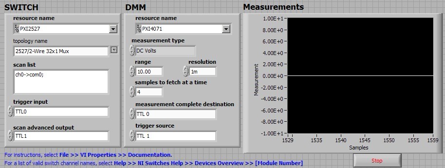
his strong 'Willy': niSwitch DMM PXI switch Handshaking.vi 4071/PXI-2527
I run the example of the handshake: "niSwitch DMM Handshaking.vi switch" for 2527 PXI DMM PXI-4071/SWITCH in a chassis PXI-1033 for a measure of 1 Volt DC test.
When I type 'Run', the switch block makes loud continuous noise "zizi"; the graph of 'measures' simply gives a 0 volt line. It's clearly wrong results.
My setting of this VI is as follows:
Anyone know what is the problem here?
Thank you
Bing
BLNG,
This noise is actually the sound of the relay control. Given that these relays are electromechanical relays, when the relay is closed, the two contacts essentially slap against each other and produce this noise. The buzzing you hear continuous, is because the relays are opening and closing several times. If you use the appliance in OR switch Soft Front Panel for example, you can hear a click by relay which is operated and closing individually each relay.
-
I tried to change the name of the PXI-4071 "DMM" that worked, but when I try to launch the "self-test" or open the app it Panel always fails. This is also true if I pass the new name of the ivi driver. Return to the name "PXI-4071" makes everything works again. Note I managed to change the name of our PXI-2530 b 'SWITCH' and the name of our SMU-6363 to "MIO" and I could pass these names to their IVI drivers and they would work.
I messed with alias VISA, IVI logical names, but nothing works unless it is called "PXI-4071.
-
I have requirment to test the MEASURMENT FULL port trigger pin in NI 4071 DMM
someone can help me with the behavior of the PIN and how can we test that?
Thanks adavance
IVI
Hello
Maybe it's what you're looking for
http://zone.NI.com/reference/en-XX/help/370384N-01/DMM/generating_measurement_complete/
See you soon
GAPO
-
4071 PXI get negative resistance readings
Hi all
We are working on a system where we measure current leakage and resistance using a PXI-4071 with some other gear as well as a map to relay SMU and 2530 b..
The main problem is that for some measures of resistance we are seeing negative values as k - 200 or - 300 k. The digital multimeter has been in the range of 10 M. My understanding is that in this mode, the applied voltage is 10V and the test current is 1uA.
For me to see a negative resistance on some paths, the voltage must be opposed the 10V and superior to 10V. Is it a specific way of thinking? SMU is switched off and disconnected from the circuit when the resistance is measured.
It is not all EHRS that show this negative tension. The EHR is all passive devices (connectors) and so they do not have any large capacitances that could store a tension that I see. I take 5 readings with auto zero done when initially 5 readings.
What causes these negative readings? The connectors are immersed in a saline solution and there should be an open between the points to measure circuit, but when they start to fail a resistance can be seen.
Any thoughts would be much appreciated. Please let me know if you want more details.
see you soon
Peter
Peter,
To answer your questions, Yes, if the digital multimeter reads - 200 k there is opposing tension on the DMM. If you use 10 M Ohms then the opposing voltage serait.2 V and if you use the 1 M Ohms then the opposing voltage 2V. Also the negative reading is also caused by the flow of the current is in the wrong direction, because if there is a negative voltage then the current flows the opposite direction.
You can check the voltage at the terminals of the resistance while taking the measurement of the resistance using an other DMM, as a handheld DMM computer. It is more than accurate enough to check the voltage at the terminals of the resistance.
I hope this helps,
Brian P.
-
Hello
We use the DMM and SMU-6363 map to test a hardware device. We will also use a PXI-2530 b switching matrix. We will use the digital multimeter to perform the measurements of voltage, DC and AC, measurements of impedance (2-wire and 4-wire), frequency and waveform acquisition. Can the PXI-4071 left be 4 wire connected (black jacks taken connected and red connected) mode and still be used to perform all other measures (including 2 impedance of the cable). This would simplify the switch connections.
Current measures use the son + and LO, but the HI and S-can remain connected. The problem you are having is if you have an active device the digital multimeter and take you a 4-wire resistance and the measurement of voltage with all 4 wires connected and then change to a current... When you do this, short-circuit you the terminals of the DUT, on that you just take the measurement of the resistance. If the terminal HAD, say, a power supply 10V, then you have just shorted out. Of course, this isn't a problem if your Instrument is a passive device, or if you change just the unused two lead whenever there is an active device of low impedance.
If you want to make voltage, current and 4-wire resistance, you need all 4 wires. If you want to do the voltage and current, you will need 3 wires, but you could connect the s + Hi and then just do the two wires. I vote running every 4 son to your DUT for maximum flexibility.
2-wire resistance is a must if you are measuring resistance above 10 MOhm. Alternatively, you can use 4-wire for all measures.
-
PXI-4071 sampling too slow when using a hardware trigger
We use 3 PXI - 4071 s in parallel to measure with accuracy of high voltages. The program is written using LabVIEW 8.5.1.
An additional test condition has been added which requires the use of a quadrature decoder and the synchronous DMM.
We thought it would be simple, using backplane trigger 0.
However, something odd happens.
With a low-cut VI that uses a single DMM, we get 100 microseconds time to sample running with internal triggers. However, if the overall relaxation or trigger of the sample is set to TTL0, the sample time becomes so 5.1 milliseconds. It seems very strange that even just definition of overall relaxation, expected to affect only the time of the first sample, not the time between samples, has that effect. The plug for the DMM also said, that the maximum trigger rate is of 6 kHz.
We have confirmed this reported sample time is independent of the speed of the clock actually connected to TTL0. If the clock is faster, it gets the reported sample time. If it's slower, the samples occur on the edges of the clock.
Does anyone know if there is a parameter that has a default that changes based on the source of command and can be changed to work around this problem, you?
I found the solution to this.
Over time the value-1, the DMM uses a short value (less than 100 US) to set hour when, in modes triggered internally. However, he used much longer (about 5 ms) when the value - 1 and with the help of a hardware trigger.
If the running-in is set to 1e-5, i.e. 10 microseconds, "the estimate" returned for conversion period goes from 5.1 ms 100, we and conversions actually occur at a rate set when clocked with trig 0-5 kHz
-
Error-1074118625 with the PXI-4071 and PXI-2527
When you use the LabVIEW and PXI-4071 PXI-2527 IVI drivers, I get a 1074118625 error in TestStand. The sequence that initializes the MUX, init DMM, connects the MUX, expected debounce, and then to the DMM reading, I get this error.
Error: niDMM .viExplanation of waveform (waveform data) reading is not found for the requested status code.
Check that the required status code is correct.
[Error code: error code defined by the user of 1074118625.]
This sequence of events is used successfully several times elsewhere in the TestStand. This error does not appear in any section of the knowledge base, or any help. Any explanation would be greatly appreciated.
I found this with google that seems like it could apply:
http://digital.NI.com/public.nsf/allkb/A593DEBFD86A69C68625727900748EEC
-
How to acquire data through several channels in parallel using E 6070 PXI, PXI-4071 and LabVIEW?
Hello
I use LabVIEW and NI PXI-4071 PXI NOR 6070E to measure the current through a variable resistance. Now, I use a single channel of SCB - 68, but I want to add another channel at the same time so that I can have two resistors instead of one that I cam measure current through them.
I have attached a Pdf file showing installation of equipment to use and code LabVIEW also.
Can someone look at these files and give me some guidelines or ideas that can help me solve this problem, please.
Thanks in advance.
Best regards
Shaheen.
Your 4071 can do a measure at a time. Your data acquisition cannot measure resistance is not she of the analog inputs.
However, you could use a multiplexer and multiplexer your 4071 DMM. This habit give you simultaneous action, but can acquire data one after the other, the speed depends on the multiplexer, you choose!
I hope this helps.
-
Problem of reliability data acquisition PXI-4071
Hello
I'm having a problem of reliability using my 4071 Pxi digitizer mode.
I have a number of tests that use the SMU-6363 (usually configured for DC) analog output to provide a stimulus for our own device, which has a number of a/d converters. We use the PXI system for calibration and testing.
1. I select a voltage ranging from tensions.
2. program the PXI-6363 to drive this tension
3 TIME about 10ms to settle. Note there no discrete capacitors or resistors in the circuit. Everything is parasitic and would generally be under the nF mark and less than 10 ohms
3. configure and Initiate() acquisition of data with the PXI-4071. In general, I use a sample rate of 1000 s/s and get about 30 samples (worth 30 ms). Activation is immediate and I used the default a queue time, 0, set the time and it doesn't seem to make a difference.
4. measure the voltage with the CDA. For debugging purposes I have sometimes made twice once before calling Initiate() and once after. The after is normal. The time required to measure the ADC is shorter than the acquisition time, but regardless of stimulation by the SMU-6363 is constant
5. extract the waveform.
6. the average waveform and compare the value of ADC measured by applying tolerances etc.
Here's the problem: it works well most of the time. But only 0.1% of the time (1 on an acquisition of 1000), I get 8-12 samples that are close to 0. It sounds like a problem of time settling (on the surface), but no matter the amount of wait time data, I always get this behavior. Not only that, but the tension before the call to Initiate() in height CDA, it always confirms that the motor voltage is already set to the programmed value. Nevertheless the acquisition presents near data 0.
So far our independent ADC always reports the expected before and during acquisition (100%) voltage. It's like the DMM input is disconnected during the acquisition during a period of time, because we have confirmed that the voltage is already present prior to the acquisition (component can). I have no errors the insider or FetchWaveForm calls. I still have all my samples. And 99.9% of the time that everything works as expected.
The DMM and ADC are connected to the same point and both are referenced to ground, and as I said before only the parasitic capacitance and resistance (cable). We use a matrix of switching (PXI-2530 (b) to make these connections. We almost always use 51/2 digits and 10V range for data acquisition.
Hello
I thought about it and was going to repost but am distracted.
The device with the ADC also has a mux and switches the mux to an internal node. It only switches when measuring and is open at other times. There is a race condition where the acquisition starts too early and maintains the acquisition after that the switch is open. Unfortunately I don't have the option to trigger.
I forgot the internal mux that I had designed the test years ago and I did some updates to improve the stability of the test. That's why we start the ADC measurement when acquiring.
I just added a routine to reject samples below a threshold
-
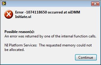
-error with the PXI-4070 107418650 same w/o autorange.
I have a PXI-1033, which includes a PXI-4070 module in slot 5. I use a version of the scanning of switch with DMM - Handshaking.vi but I changed to read a list of fixed scanning and I have replaced the meter of while loop with a fixed reading of 144 samples. After the execution of the present VI about 47 times I get this error:
I am NEITHER-DMM 3.0.4 OR-DAQmx LabView 2101SP1 9.3.0f2 and Vista Business 32-bit slot. I use 4 resistance wire and tried both auto and fixed the range with the same results. Before this loop the related single DMM functions is to read resistance readings 4 son and close the DMM. This seems to loop forever without any problem.
Dozens of times to restart a day gets old fast, any ideas?
Maybe you are looking for
-
Difficulty of readability of the poor fonts in firefox
The type on half the screen of Firefox superior deteriorates when scrolling. This isn't a problem in the Solution Explorer, only Firefox. I have a screenshot, but I do not see how to add it here.
-
Hello I built a vi that performs the FFT of a signal (~ 200,000 admissions in a 1 d table), during its operation, I'm not sure it will output the correct answer (or at least it is not sensible for me). I'm trying to find the frequency of distribution
-
Order of execution for explicit file dialog boxes and query the user input dialogue
Hello In my VI I use 1 and 2 express file dialog boxes prompt the user for input dialogue box. Y at - it any easy way to determine an order of exuction for these express dialog boxes? Or I have to use screws to notify? In fact, I just need the input
-
My family disappeared from active contacts not to recycle
I lost all my contacts in live mail and folders also disappeared
-
Suspected Trojan unauthorized sent emails
4 emails were "sebt' my account msn.com to users in my Contact list." I / others should do?