5-pulse measurement time
I need to measure the speed of a motor that has a way-out load, so the instantaneous speed of the engine looks like a sine wave. I have 5 impulses of hall by a revolution, I so want to measure the time of 5 impulses hall and convert it to a frequency to basically filter speed fluctuations. The hall pulses to measure frequency range is from 4 Hz to 50 Hz. I have two engines that must be measured in this way and two counters available on a 9172 with a module 9411. I tried most of the shipped examples, but I had no success trying to filter the speed fluctuations. I'm using LabView 2009.
This will not work if it isn't jump impulses in the train. I ran the vi and periods seem correct for 5 consecutive pulses.
Thank you
Brian.
Tags: NI Software
Similar Questions
-
measurement time and openness 4132
Hello
I use a 4132 SMU with a switch 2531 to measure different resistance in an electric circuit. I use a brief biphasic pulse of 50ms ~ to measure resistance. My problem is the measurement time if long - it seems that the minimum pulse width I can do is a 30ms pulse in a polarity and a pulse ~ 40ms in the other polarity. I disabled 'way' that knocked 20ms on each phase, but I am still left with a ~ 70-80ms measure, but I wish it were half that, if possible. The only other way I can see to minimize the measurement time is at the bottom of the window opening, but any if I increase or decrease the time of opening, the measure takes about 10 x longer if the opening is none other than 1 PLC.
Attached is the Subvi I use to measure the unique resistance value. Note that first I close the relay to solve part of the circuit and then configure the SMU and then get several measures, one for V (+) and one for the (-) V. This measure will be repeated 15 times in quick, although succession with different closed relay, which means that the SMU gets reconfigured/initialized 15 times with the same parameters, so maybe that's my problem. I have not ventured into the handshake, but I would like to know if there is anything else I can do since the handshaking deal would take a lot of programming. In any case, when I run the VI several times, there are only 8 ms between biphasic pulses, so the reconfiguration may not take THAT long.
I posted a jpg file of the time trace of the impulse it generates (10,000 samples per second). Note that the first phase of the pulse is a different length of time that the second phase: there is nothing in the program that would cause - it would be more logical if the first phase was more time on behalf of increasing the time for the configuration of the SMU. So I have sort of a bunch of problems here: 1) cannot reduce opening time 2) want to avoid a handshake VI if it means hours and hours of programming, 3) uneven pulses. I hope someone can point me in the right direction!
Thank you very much
GimNPC
gimNPC,
As mentioned earlier, you should not call Reset every time at the end of the method. Instead, set the output to 0 c. Moreover, all the attributes that are not changed will not need to be reconfigured, which will speed up the loop a little (maximum, that I would expect several milliseconds).
When you call niDCPower Reset, the opening time is reconfigured. On the 4132, anytime, the opening time is reconfigured, must wait a minimum of time to allow a measure being erased. It is because of the behavior of one of the hardware components that we use. If you prevent the reconfiguration of your opening time during each run, your speed should be improved significantly.
Please let us know if these suggestions help, or if you have any other questions.
Thank you
Tobias Gordon
Software engineer
DC accuracy
National Instruments
-
Measurement time 4132 SMU is too high
Hello
I use PXI - 4132 DC EMS to perform some DC measurements at high speed. I just took a 1 K Ohms resistance, forced 1mA and measure 1V. I have this done configuration and code completed. I get the correct measurements. But my problem is with the measurement time. The total duration is about 45ms to complete installation and measurement, with the exception of the 'initialize and close '.
I checked the time at every step and I noticed that the maximum duration is taken during the "voltage reading. Out of the total 45ms, it takes about 34ms just for a measure. It's just a VI "Ukraine power measure" takes about 34ms, which is ridiculous compared to the Kiethleys. I tried to vary the time of "openness" and turn off the 'Auto Zero'. But the measurement time is still high. Can someone help me and let me know what is the best time of the measurement obtained with 413 x series SME?
Thank you!
Hey Phx_tech,
The amount you reduce your delay source depends very much your HAD and how regular you have to your level of tension until you start taking your measurements. If your Instrument is reactive, you can see discount gas and unintentional ringing during the transition from your output level and therefore would allow enough break-in before taking your measurement. The best thing to do is to experiment with different delays of source and see how much delay need you to get a consistent and reproducible measure. If you have a scope that is available, it will also show you the step response of the SMU with your Instrument. If your first reading is higher than your other readings, that this could very well be a problem with not enough time settling. What kind of DUT Testez_ you?
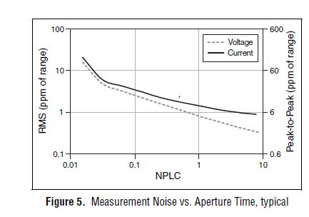
From page 4 of the specification, you can see that 1 PLC, we can expect about 1 ppm RMS noise of the range to 1 PLC. This means in the range 10 au our measurement noise would be 10 pA RMS or 60 pA pk - pk. However, your DUT + cables will pick up the extra noise and you should consider using wires of twisted shield pair to reduce noise picked up in your system. The shield can be terminated at the mass of the chassis on the side EMS of the cable to help reduce noise appearing in your measurement.
Let us know what you find after experimenting with you HAD.
Thank you!
Brandon G
-
How can I measure time my Boolean indicator light lights up.
Joined the VI
Thank you
-
How to take the measurement time of waveform.
Hello
I faked a square signal I need to measure the period of time without interruption... automatic measurement of the time for one cycle...
For example, I have square wave, and I need to measure the period of time and display it without attributing all outside sliders... I need automatic measurement of it...
is that what you want?
(I just added the period detect your VI)
-
Is there a way to measure time on the timeline?
Often, I want to know how long there is between the clamp a and clip b on my calendar. I can move the cursor to the beginning and the end of the clips and do the math in my head. But is it a creation tool that will do this for me? I am considering something where you slide and exposing a part of the timeline and first tells you how long the game is.
J. D.
I am considering something where you slide and exposing a part of the timeline and first tells you how long the game is.
You're in luck; This exists. Just make sure that the Info Panel is visible and then either lasso or shift + click multiple clips. The info panel displays something like "5 items selected. Duration: 00 00 10; 00 ''. Even easier, just Shift + click on the first and the last clip of the order that you want to calculate, and you will have the total time to develop the first element and the out point of the last; He will not make a difference if you select the clips between the extreme values.
For what it's worth, I put the SHIFT + 9 to be a hotkey to call the Info Panel with impatience for the same reason. This is a feature very convenient, often neglected Agency.
-
measuring time between 2 signals
Hello:
I want to use the sequence attached to verify the relationship of input voltage (Vi) ship & output current (Io).
I build 2 arraies VI and o with loop at the same index.
How can I get the delay between the Vi and Io signal?
Thank you!
Please check the enclosed sequence.
-
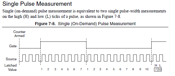
single pulse width measurement
Hello
I'm trying to measure the duration of a single pulse using ctr0 on an SMU-6361.
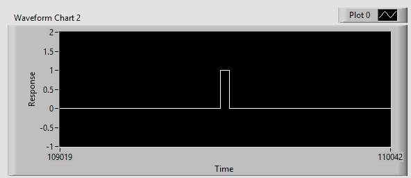
The signal in the attachment Capture7.jpg, goes PFI 9, ctr0 door.
The problem is that the counter see ' s the front up and stops. The pulse width is not given as can be seen in the output (Capture8.jpg).
I get the same results by using Meas_Pulse_Width.vi example.
Is something wrong with my SMU-6361?
Oh, I think I know what it is.
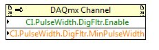
Change the task "pulse width" (a single pulse of height) instead of "Pulse" (the high and low time of a pulse repetition measures). Change the DAQmx Read to use Ctr > single sample > DBL (instead of pulse). Change the property filter node digital to use the corresponding properties of the "pulse width" (the filter is still necessary):
The task of the pulse was not period initially because you receive a series of noise pulse repetition (and so it was a very low period). With the filter, this time since the noise disappears now and the single pulse did not finish measuring the pulse (which requires a high and some time):
For the record, I agree that it is confusing that there is the "pulse" and "Pulse" measure and they do different things.
Best regards
-
Hallo,
I use the following system:
- OR PXI-1044 with controller NI PXI-8109
- OR PXI-2564 switch module to turn on the monitor of my test device
- Data acquisition multifunction NI PXI-6259 to measure the signal that responded to the questionnaire jump
The two cards are the same - PXI trigger bus. For both, PXI-2564 and PXI-6259 I use DAQmx to set the reading and writing of the channels.
Now, I want to measure the time between the digital output, my unit turns and the analog input, which measures the response of my system.
I can't do work by myself, please help me!
I thank Ludwig.
Hi Ludwig,.
If you can't give us any VI we have difficulties with to help you.
Because I Donat knowledge how your program is mounted it is not easy to know where you should enter signals.
Here's a question similar to yours:
http://forums.NI.com/T5/LabVIEW/best-way-to-measure-time/TD-p/178704
and 2 external links:
http://www.ehow.com/how_8698983_measure-time-LabVIEW.html
http://objectmix.com/LabVIEW/385152-how-can-i-use-LabVIEW-measure-time-between-analog-pulses.html
-
Measure the time of the rising edges of a digital stream using a USB-6341
I have a DAQ USB-6341 map.
I use Measurement Studio (writing code in c#) on a Windows 7 computer.
I'm relatively new to the DAQ cards, programming, so I could ask something that is obvious (sorry if this is the case).
I went out a stream of digital pulses to an analog output channel. I wired this channel to one input of the meter channel. I am able to measure the number of edges upward to the inlet of the meter channel (since the digial flow is continuous, the number of rising edges increases with time).
I would like a time stamp of each rising transition and I like to keep these timestamps in a table without ever growing (or maybe bin these timestamps in a histogram).
Set up the meter channel to provide the timestamp data? (rather than just count)
Thank you for your help.
WRB,
The meter must be able to measure the relative time between the different edges of your signal. To do this, you will take care to set the meter to measure time. It will measure how long a full period of your signal takes. You can configure edge that you want to start with. You'll want to set up your timed 'implied' measure. This sets up the meter to automatically take action whenever a period is over. While it's not exactly a timestamp, you can find the distance between two edges by adding the time periods between the banks in question.
I see another technique that you can use. This would put the counter to edges of County one of the basics of time of your device (it has 100 KHz, 20 MHz and 100 MHz bases long). Then configure the task to use your signal as a sample (configuration to use rising edge) clock. Whenever the song occurs, you will get the number of ticks ticks selected timebase that took place at that time. One thing to note here, however, is that the counters are 32-bit wide, so your code will have to manage the overthrow of this charge if you are using a fast time and base running for long periods of time.
Hope that helps,
Dan
-
How to measure the width of pulse with MyRIO
Hello
Sorry in advance if this is not the most appropriate forum. I'm not entirely sure if it's a more general problem of 'software' or the MyRIO-specific. I have searched the forums and found a few related topics but could find no one who help me in this context.
I'm trying to measure the width of a sensor pulse ultrasonic ping. It emits a signal conditioning - the time that it is high directly corelates how far is the object. Being new to LabVIEW I am confused as to how do I calculate the time it remains high.
I read that LabVIEW should not need to 'variables' as in python or C, for what is the best way to measure time, the signal is high? Normally, I'd go (new_time - old_time), but obviously I can't store an old time in LabVIEW as I would in python or C.
Other notes:
I have the sensor correctly ping echoing and I can see the blips on a chart and see a perfectly square wave valid.
To answer your question on how you would in LabVIEW...
While LabVIEW has not stated/named variables that you have in a language based on text, the data is stored on the wires. You can use the nodes as node registers or shift of feedback to store values between iterations of a loop:
(this will keep subtracting y (starting with 0) and store the result for the next time it runs)
LabVIEW also has functions in the range of mathematics/signal processing to make the detection of pulse on a waveform.
-
Full range of pulse width measurement
Hello
I'm having a problem with the measurement of PW, I need to read an operating cycle within a range of 0% to 100%. The problem I have is the signal does not cross the Middle time enough baseline to measure or the histogram cannot be used because the amplitude is zero. Yes, this is obvious, because there is no pulse, that's basically all true or all false these two extremes, but the pulse measurement vi cannot handle this. Is there another way, I could measure the market factor, so that I can see if there is a hollow (0%) or high (100%) and everything in-between without errors? Even when I measure the PulseWidth in the method of the Ridge, rather than the histogram method, which gives me more time to remain at 0 or 100% before it gives an error, the measure see the signal as duty cycle 50% (still a times obvious because it is neither salvation nor low for any length). So if I could still read 0% or 100% error free, how would I be able to block the two extremes of the never read? My entry is the acquisition of data, so I can't just 'limit' my input to the source signal...
Any suggestions?
Thank you
-Corbin
Hey, Henrik, thanks for the reply,
I didn't really know how to integrage over a period of time in LabView, and I read a wave of digital squares (duty cycle). I found that I needed to omit extreme values such as 0% and 100%, so I couldn't find a way to do this with one under VI. What I found is my solution: I knew that + 12V has to be 100%, and 0 v is expected to be low, so I just used 'Amplitude and level measurements' sub VI read the RMS value, used a table that I recorded correspondence (via MatLab help), and I have more problems with errors due to levels of reference of histogram (do not use histogram now...). My application can read everything from 0% to 100% and he returned my correct data after handling. Success!
He could go about resolving the issue differently, but it works.
-Corbin
-
Measurement on the side time server? Best practices for the turn-based game
Hello
What would be the best practice for measuring time in a turn based game?
I was looking at the timeout of the room, but to use that it would mean that, for each round, I put users in a new room?
Is there a way where I can measure time serverside and keep users in the same room?
If so, I could use php, otherwise, we would need java that allows to measure a time race.
See you soon,.
G
Hello
You can definitely use PHP or Java - we provide integration of server
libraries for either. I don't know exactly what is the use case, so I can't
comment on what makes the most sense, but if it is not information which must be
totally secure, grading on the client can be a viable approach also.
Nigel
-
measure the distance between 2 impulses (PCI-6221)
Hello
I have a digital signal that sends a pair of impulses (100ns width each) roughly every 100ms and I measure the time between two pulses of a pair (with a resolution of 100 ns).
For the moment, I got a card PCI-6221 to accomplish this task. Unfortunately, I have no solution until now only measures of counter, I found measure time between constant frequency signals, i.e. they cannot measure the distance between 2 single pulses.Any help / ideas / or even telling me that it is impossible to solve this task are appreciated
Are the two pulses on the same line?
If so, you need to just configure a task of the measurement period. If they are on separate lines, you would use a task of "separation of two-edge.
You might be to throw off by the timing of it:
If you do not configure implicit synchronization in your task, will start on the first edge after DAQmx Read is called. Thus, in order to intercept the signal, that you must configure your task, call DAQmx Read and then start your two squares.
If you want the task to control the signal continuously, you must configure name timing. In this case, you will receive a sample on each rising edge of the external signal (assuming that the two impulses on the same line) - If you start the task of counter before starting the production of pulses (which you probably should), then the same samples correspond to the time between pulses, the odd samples would be the time between each series of pulses.
More information on modes of counting on the 6221 lie in the M series user manual.
Best regards
-
create time rise, to shooting in chart
I using temperature control pid co, now, I want to plot the graph of the responsibility, but I can't identify the ascent of the day, setting the time, the percentage of overrun, can any body help me.Please,help help me
Hi theinbeihn,
What exactly is the PID function that you use?
Lynn is right, the pulse measurment vi will help with that. I am also looking to find that the other Lynn VI described.
Ricky
Maybe you are looking for
-
By connecting to: https://service.oneaccount.com/onlineV2/OSV2?event=login & PT = 1 Report seems to crash the whole browser. This was a problem since you upgraded me to 17.0.1. Have just tried the same operation with report running on IE8 and no prob
-
Bookmarks will not save. I tried all the solutions published to date, is there an add on?
I noticed in the last few months that would save a number of bookmarks in the toolbar or bookmarks menu. When I closed firefox and then returned to his bookmarks were not there. It's as if firefox is blocked at a certain point in time. I use sandboxi
-
Satellite M70-193: installation of the graphics driver - issue minimum requirements
I can't install the driver on my M70-193, this meesage is coming "this system does not meet the minimum requirements for installing the software. Setup will close. What can I do? Thankss...
-
I'm using LabVIEW on two different machines, and the laptop has a little strange problem with MAX. All the code works except that on the laptop, for some strange reason, the shortcut icon on the desktop is no longer same old blue globe with a yellow
-
How can I update a single parcel in multi graphic of xy trace?
Hi all I'm working on a 'before' HMI for a larger acquisition/analysis system, which includes monitoring the continuous performance of a turbine. The results of the measurements are stored arrays of contour lines, which represents the openings of tur