measuring time between 2 signals
Hello:
I want to use the sequence attached to verify the relationship of input voltage (Vi) ship & output current (Io).
I build 2 arraies VI and o with loop at the same index.
How can I get the delay between the Vi and Io signal?
Thank you!
Please check the enclosed sequence.
Tags: NI Software
Similar Questions
-
Measure the time between the ridges of the periodic input signal
We have built a circuit which is supposed to mimic an Exercycle. We have an IR switch and a spinning wheel, the rccb meets a comparator circuit and the output of the element of comparison, we have running in LabView. We successfully were able to measure the number of rotations of the wheel and the total distance travelled by the wheel, but are struggling to measure speed. We cannot find a way to measure the time between picks in real time, which we could then divide the wheel circumference and calculate the speed in real time. The VI I posted has a square wave simulated rather than the signal we receive on our circuit. Thanks in advance for the help.
Jon and David
I think you're overloading the things trying to get the time between two pulses. Instead, you can use the VI Express your measures and select frequency for her custom. Then, you can multiply the circumference of the wheel of the frequency to get the speed.
I hope this helps.
-Christina
-
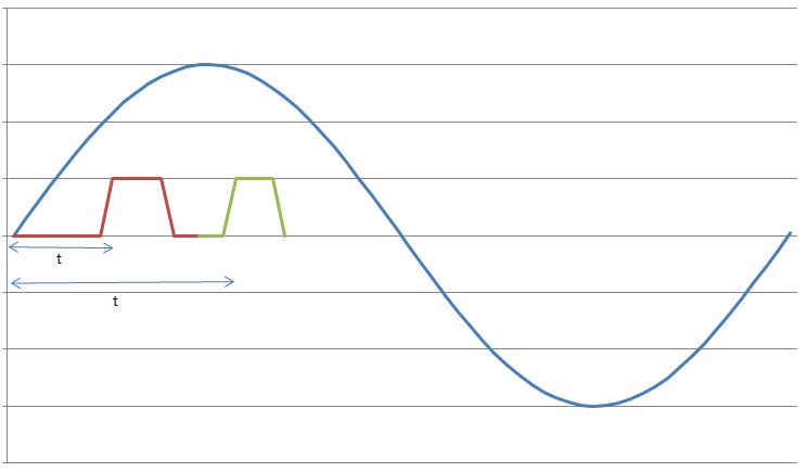
I have a sine wave of 50 Hz and a pulse of the signal on the same chart. The difference in phase between the two is between 0-90 degrees.
Now I need to calculate the time difference between (when the sinusoidal wave passes through zero volts) and (when the pulse increases). The frequency will remain about even for the two signals.
The request is for a three-phase generator. In simple terms, when the difference in time between the passage to zero of the sine wave and pulse increases increases, it means that the load on the generator has increased.
I am a novice user of LabView (version 9, 2009), maybe it's a very simple problem but I was pulling on my hair for the past few days and couldn't understand anything. Any help would be greatly appreciated. I use DAQ USB-6008 to measure these tensions and the impulse of the generator and a sensor
I have attached a jpg file (a graphic that I just did with excel to explain). The time 't' is what I'm trying to measure
See you soon
Zdzislaw
Awais.h,
For problems of this kind I recommend start writing the granular steps you would take to manually fix this problem. You can't say LabVIEW (or any programming language) If you can't succinctly describe the solution to your problem.
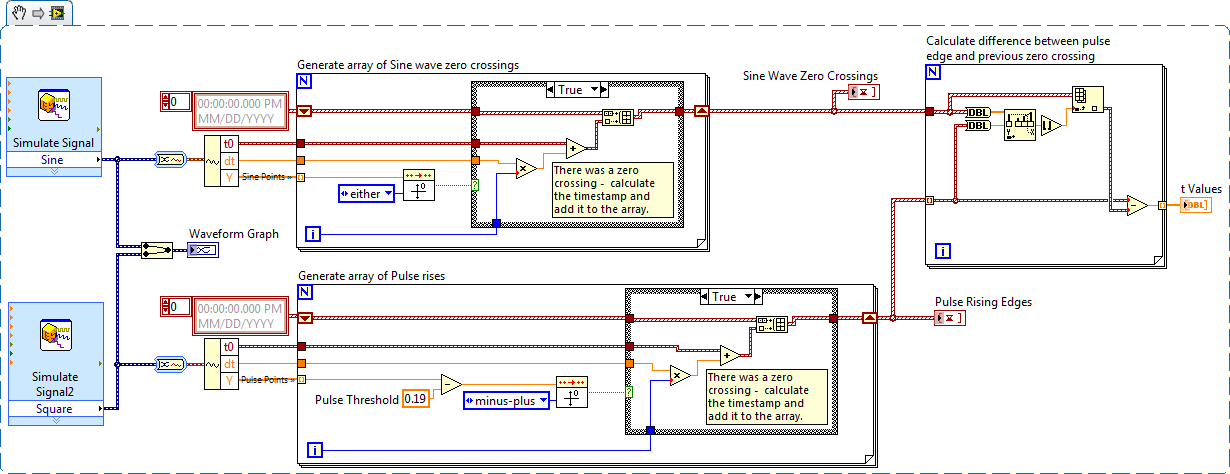
The I want to address this problem is to:
- find all the zero crossing points and edges on the rise
- for every rising edge find the difference between the timestamp and previous passage by zero
Here is an implementation of this algorithm LabVIEW:
-
How can I measure the time between each two successive increase edges, using digital input?
Hello
I have tried two measure the time in seconds between each two successive rising edges on a digital input.
So far I managed to detect the rising edge, increment a counter at each rising edge and take the time during which the increase is edge
all I need now is subtract edge currently rising from the previous era of edge rising to calculate (T), which can be 1/frequency and display in real time for the user.
but I do not know how to do this

Can someone help me please!
Woah!

Sorry Apok, but your code becomes much too complicated and salty. I don't think that all records to offset or Boolean conversion/operators are necessary at all.
If you want to measure the time between two keys so it's another (much less complicated) way. It simply records the time when press button in a registry change, then compares the two.
-
Measure the time between two digital pulse
Hello
For a non-critical calendar application, I need to measure the time interval between consecutive TTL pulses, ranging from the order of 0.5 s for a few seconds, with a low accuracy of +/-10-50ms. The interval being measured varies between the rising edge of the first pulse and the front of the next and so on.
I have several input lines I need to deal with. Because it's a critical machination low cost, I don't want to use digital counters for each line, so I work with an acquisition of data USB6008 and have connected the input rows TTL on the digital inputs of the device. Avoiding will be sufficient.
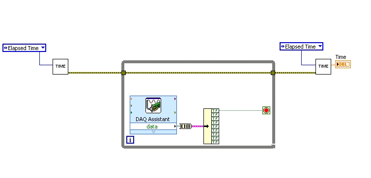
I found a good example of VI on discussion forums that does almost the same thing, only it uses instead of the DAQ Assistant user input. The VI works including the time the program going on in a while loop. I replaced with the DAQ Assistant output (a channel) user input in the hope that it is still work.
When I run the program in "run once" mode, it seems to work perfectly. However, in "continuous run" it measures only a very small interval, probably just the time between two samples. I think it has something to do with the help of a while loop in combination with the DAQ Assistant. Anyone who has any suggestions how to solve this problem?
Thank you!
OK... first of all, you should never use the button "run continuously. I wish that NEITHER would be to eliminate it, but told me that it is sometimes useful for debugging. If you want your program to run over and over again, use a while loop with a stop"" button.
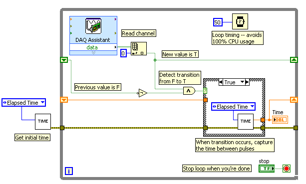
If I'm reading your code correctly, you make your initial moment, and then collect data from data acquisition. When one of the channels is "T", you stop your loop and the end time of capture. (By the way, why you convert your table to a cluster? Why not just index the appropriate channel in the table directly?)
Since you want to capture the time between two consecutive pulses, you need to know when a transition has occurred... i. e when your digital line went from F (no pulse) to T (pulse start). This will give you your forehead. Right now, all you're doing is looking for a value T - so you have no way of knowing if you are looking for to the previous impulse again, or a new impetus. You also burn 100% of your processor with the way you have your programme in place.
You need a small loop delay so that your VI is not 100% of your hogs CPU time. Given that you can live with an accuracy of 50msec, what I suggest that you use.
See attached picture for you give an idea of how to implement. He will probably need some refining operations, but it should point you in the right direction.
I hope this helps.
-
measurement time and openness 4132
Hello
I use a 4132 SMU with a switch 2531 to measure different resistance in an electric circuit. I use a brief biphasic pulse of 50ms ~ to measure resistance. My problem is the measurement time if long - it seems that the minimum pulse width I can do is a 30ms pulse in a polarity and a pulse ~ 40ms in the other polarity. I disabled 'way' that knocked 20ms on each phase, but I am still left with a ~ 70-80ms measure, but I wish it were half that, if possible. The only other way I can see to minimize the measurement time is at the bottom of the window opening, but any if I increase or decrease the time of opening, the measure takes about 10 x longer if the opening is none other than 1 PLC.
Attached is the Subvi I use to measure the unique resistance value. Note that first I close the relay to solve part of the circuit and then configure the SMU and then get several measures, one for V (+) and one for the (-) V. This measure will be repeated 15 times in quick, although succession with different closed relay, which means that the SMU gets reconfigured/initialized 15 times with the same parameters, so maybe that's my problem. I have not ventured into the handshake, but I would like to know if there is anything else I can do since the handshaking deal would take a lot of programming. In any case, when I run the VI several times, there are only 8 ms between biphasic pulses, so the reconfiguration may not take THAT long.
I posted a jpg file of the time trace of the impulse it generates (10,000 samples per second). Note that the first phase of the pulse is a different length of time that the second phase: there is nothing in the program that would cause - it would be more logical if the first phase was more time on behalf of increasing the time for the configuration of the SMU. So I have sort of a bunch of problems here: 1) cannot reduce opening time 2) want to avoid a handshake VI if it means hours and hours of programming, 3) uneven pulses. I hope someone can point me in the right direction!
Thank you very much
GimNPC
gimNPC,
As mentioned earlier, you should not call Reset every time at the end of the method. Instead, set the output to 0 c. Moreover, all the attributes that are not changed will not need to be reconfigured, which will speed up the loop a little (maximum, that I would expect several milliseconds).
When you call niDCPower Reset, the opening time is reconfigured. On the 4132, anytime, the opening time is reconfigured, must wait a minimum of time to allow a measure being erased. It is because of the behavior of one of the hardware components that we use. If you prevent the reconfiguration of your opening time during each run, your speed should be improved significantly.
Please let us know if these suggestions help, or if you have any other questions.
Thank you
Tobias Gordon
Software engineer
DC accuracy
National Instruments
-
Let a burn of LED on a random time between 3 and 7 seconds
Hi all
Probably, it's a matter of simpel for many of you, but not for me. I try to make a counter reaction time. And I hope someone can help me with the first part: the led must Flash on a random time between 3 and 7 seconds.
After this need to measure the time between burning directed and by pressing the stop button
Results ranking in a table
After the display of ten measures of response time average.
I hope someone can help me to launch it, I need it for school.
Thank you!
Matthijs
Netherlands
Code Simon put tapped off. The Down button was a nice touch, but cannot be disabled so we were testing times preaction and the param 'Trial' could get pretty messy especially on a series of rehearsal
-
How to find the time between two channels of entry in the data acquisition card or pci 6036
Hello
I read a lot-related posts on the simultaneous measurement of two input voltage of similar channels in map data acquisition. I know that the best material is "simultaneous measurments of the Series DAQ cards" but I only pci data acquisition card 6036 and I try to understand what is the time between the reading of the two channels . This period is always constant? (must it rely on a voltage (amplitude, frequency, waveform..). I send the sine wave (s) to the two channels and read the values of V, if they read the same value, the difference should always be zero but I get-0,002 to 0.002 Volt difference (I must find a way to convert it in time). A screenshot of my VI is attached. I wonder how I can accurately measure the time delay between the channel.
I am open to any suggestion, my final goal to read exactly two channels at the same time ((ou connaître le délai exact donc je peux correspondre les données correspondantes étant donné le temps de retard))
Hi spinup,
better you should post your question in the forum of LabVIEW, LabWindows/CVI is used

Good luck.
-
Measurement time 4132 SMU is too high
Hello
I use PXI - 4132 DC EMS to perform some DC measurements at high speed. I just took a 1 K Ohms resistance, forced 1mA and measure 1V. I have this done configuration and code completed. I get the correct measurements. But my problem is with the measurement time. The total duration is about 45ms to complete installation and measurement, with the exception of the 'initialize and close '.
I checked the time at every step and I noticed that the maximum duration is taken during the "voltage reading. Out of the total 45ms, it takes about 34ms just for a measure. It's just a VI "Ukraine power measure" takes about 34ms, which is ridiculous compared to the Kiethleys. I tried to vary the time of "openness" and turn off the 'Auto Zero'. But the measurement time is still high. Can someone help me and let me know what is the best time of the measurement obtained with 413 x series SME?
Thank you!
Hey Phx_tech,
The amount you reduce your delay source depends very much your HAD and how regular you have to your level of tension until you start taking your measurements. If your Instrument is reactive, you can see discount gas and unintentional ringing during the transition from your output level and therefore would allow enough break-in before taking your measurement. The best thing to do is to experiment with different delays of source and see how much delay need you to get a consistent and reproducible measure. If you have a scope that is available, it will also show you the step response of the SMU with your Instrument. If your first reading is higher than your other readings, that this could very well be a problem with not enough time settling. What kind of DUT Testez_ you?
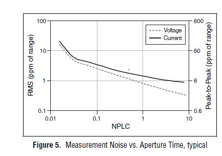
From page 4 of the specification, you can see that 1 PLC, we can expect about 1 ppm RMS noise of the range to 1 PLC. This means in the range 10 au our measurement noise would be 10 pA RMS or 60 pA pk - pk. However, your DUT + cables will pick up the extra noise and you should consider using wires of twisted shield pair to reduce noise picked up in your system. The shield can be terminated at the mass of the chassis on the side EMS of the cable to help reduce noise appearing in your measurement.
Let us know what you find after experimenting with you HAD.
Thank you!
Brandon G
-
How can I measure time my Boolean indicator light lights up.
Joined the VI
Thank you
-
I use VISA in communication series with PIC18F4550 (mcu, USB copy series), I found if I read immdiately afte writing, I can't get the right data all the time. It seems that the time should be at the same time between write and read funciton, and delay must be greater than 0.35 sec.
Fact delay is necessary or I used to misuse Scripture VISA and playback function?
Also look at the use of the chariot of termination and the setting of time-out to your advantage.
1 turn on the tank of termination (depends on YOUR DEVICE PIC18F4550, read the instructions)
2 set the timeout to something MUCH longer than necessary. (like 1000 ms)
Write then followed the reading. No delay, bytes read no. to the port
For the bytes of lonely bytes expected reading feature request.
The Read function will wait for the full message that ends with the chariot of termination and will return with your message as soon as he gets the chariot of the termination. Or will he wait until the timeout before giving up on your device.
You can then decide what to do with if time-out error message never comes.
I have devices that take more than 3 seconds to answer because they have to go do something before they can meet. Some of my exhalations runs to as high as 10 sec. I have set the timeout on the fly, based on the order that I send.
-
Hey guys, Hello.
I need to calculate the time between 2 summits and it does not work very well.Can you help me?!
I'm using NI USB-9221, with 2 channels.
I need to calculate the time between peak (12 volts) of channel 1 and channel 2.
Here's my attached .vi.
Thank you very much for the help.
This is!
-
Take the time between two values
Hi people,
I have a problem and I know idea how to solve... I need help.
The problem is I want to take the time between two values max as you can see in the chart.
For example, in the image that I have add
4.5 - 1 840 = 2.66
And enter this value in the 'time between mostra '.
It's that I want...
But what I think is very complicated, because I don't know how to take the time correctly and does remove...
Thank you very much
Any solution?
Hi jocuma,
I tried something and hope that helps u.
Just create two arrays of temperature and voltage. First of all, I'll get the value of the voltage when it is more of a certain value and that same index to get the value of time and store in the shift register.
When I get the second higher than the limit value, I'll get time and subtract the previous value.
-
the BACKSPACE key does not work properly and when I want to type a leter twice I have white some time between them
Hello
In what program?
Don
-
Nor-Daq 6251 set hour/time between samples
I'm trying to calculate the expected error for an experience that I do and I don't know if I've done enough to determine the 'break-in' or the time between samples.
We use 8 differential channels to the maximum sampling frequency, the card can do (1.25. MECH / s). If I understand correctly, the minimum time between each sample must be 1 / 1.25 M, or 800 nanoseconds, such as the maximum time between sampling channel 1 and channel 16 would order 12uS (800nS * 15). If the expected voltage settings are the same for each channel (+/-10v), would a break-in? If so, how long?
In addition, if a channel is upward, and its tensions have an offset, DC on 5 or 6 volts, should that severely increase break-in if all other channels averaged about +/-1v?
I'm sorry for the basic question, I couldn't find a straight answer in the documentation.
Hi LSUgrad85,
When looking for specific device information detailed Specifications for this device will usually provide the details you are looking for. After the back if you have questions about the information in the detailed specifications.
I hope this helps!
Kind regards
Maybe you are looking for
-
A bizarre, pulling on my hair. My Gig Ethernet connection (be it through Apple's Thunderbolt, or USB adapter generic ones) will start to go down. The behavior is that it is impossible to acquire an IP address, switches to Wi - Fi, then gets an addres
-
Satellite L775 - 12L refuses to open the SD card
Hello! I have a recent problem with my laptop L775 - 12L about the SD card reader. Since yesterday my computer refuses to open the SD card while working always before.I did nothing with my computer and now when I insert my usual SDHC card 8 GB asks m
-
Wrong with OSX El Capitan Safari 9.0.3
Hello I've just updated to OSX El Capitan and now Safari 9.0.3 does not work properly, I can not enter the information in the entry bar to address/search top of web page that he won't let me physically type anything in it, nothing does not appear whe
-
Presario CQ43: Compaq Presario do not start when the hard disc
So I got a laptop at home lying around, I put a hard drive in it and it won't do anything. The screen is empty without lights or beeps. ; The only light is the power button which turns off after a few seconds. When I take what he says f30 no HDD inst
-
Get the distance of kinect sensor depth with kinaesthesia
Hello How can I get the distance to the nearest object? I use kinesthesia toolkit.