Measurement time?
How can I measure time my Boolean indicator light lights up.
Joined the VI
Thank you
Tags: NI Software
Similar Questions
-
measurement time and openness 4132
Hello
I use a 4132 SMU with a switch 2531 to measure different resistance in an electric circuit. I use a brief biphasic pulse of 50ms ~ to measure resistance. My problem is the measurement time if long - it seems that the minimum pulse width I can do is a 30ms pulse in a polarity and a pulse ~ 40ms in the other polarity. I disabled 'way' that knocked 20ms on each phase, but I am still left with a ~ 70-80ms measure, but I wish it were half that, if possible. The only other way I can see to minimize the measurement time is at the bottom of the window opening, but any if I increase or decrease the time of opening, the measure takes about 10 x longer if the opening is none other than 1 PLC.
Attached is the Subvi I use to measure the unique resistance value. Note that first I close the relay to solve part of the circuit and then configure the SMU and then get several measures, one for V (+) and one for the (-) V. This measure will be repeated 15 times in quick, although succession with different closed relay, which means that the SMU gets reconfigured/initialized 15 times with the same parameters, so maybe that's my problem. I have not ventured into the handshake, but I would like to know if there is anything else I can do since the handshaking deal would take a lot of programming. In any case, when I run the VI several times, there are only 8 ms between biphasic pulses, so the reconfiguration may not take THAT long.
I posted a jpg file of the time trace of the impulse it generates (10,000 samples per second). Note that the first phase of the pulse is a different length of time that the second phase: there is nothing in the program that would cause - it would be more logical if the first phase was more time on behalf of increasing the time for the configuration of the SMU. So I have sort of a bunch of problems here: 1) cannot reduce opening time 2) want to avoid a handshake VI if it means hours and hours of programming, 3) uneven pulses. I hope someone can point me in the right direction!
Thank you very much
GimNPC
gimNPC,
As mentioned earlier, you should not call Reset every time at the end of the method. Instead, set the output to 0 c. Moreover, all the attributes that are not changed will not need to be reconfigured, which will speed up the loop a little (maximum, that I would expect several milliseconds).
When you call niDCPower Reset, the opening time is reconfigured. On the 4132, anytime, the opening time is reconfigured, must wait a minimum of time to allow a measure being erased. It is because of the behavior of one of the hardware components that we use. If you prevent the reconfiguration of your opening time during each run, your speed should be improved significantly.
Please let us know if these suggestions help, or if you have any other questions.
Thank you
Tobias Gordon
Software engineer
DC accuracy
National Instruments
-
Measurement time 4132 SMU is too high
Hello
I use PXI - 4132 DC EMS to perform some DC measurements at high speed. I just took a 1 K Ohms resistance, forced 1mA and measure 1V. I have this done configuration and code completed. I get the correct measurements. But my problem is with the measurement time. The total duration is about 45ms to complete installation and measurement, with the exception of the 'initialize and close '.
I checked the time at every step and I noticed that the maximum duration is taken during the "voltage reading. Out of the total 45ms, it takes about 34ms just for a measure. It's just a VI "Ukraine power measure" takes about 34ms, which is ridiculous compared to the Kiethleys. I tried to vary the time of "openness" and turn off the 'Auto Zero'. But the measurement time is still high. Can someone help me and let me know what is the best time of the measurement obtained with 413 x series SME?
Thank you!
Hey Phx_tech,
The amount you reduce your delay source depends very much your HAD and how regular you have to your level of tension until you start taking your measurements. If your Instrument is reactive, you can see discount gas and unintentional ringing during the transition from your output level and therefore would allow enough break-in before taking your measurement. The best thing to do is to experiment with different delays of source and see how much delay need you to get a consistent and reproducible measure. If you have a scope that is available, it will also show you the step response of the SMU with your Instrument. If your first reading is higher than your other readings, that this could very well be a problem with not enough time settling. What kind of DUT Testez_ you?
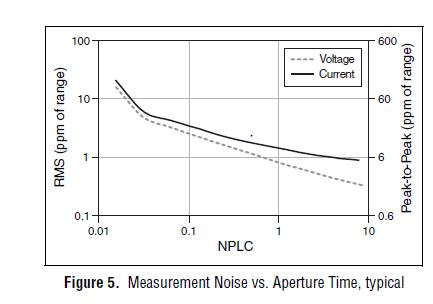
From page 4 of the specification, you can see that 1 PLC, we can expect about 1 ppm RMS noise of the range to 1 PLC. This means in the range 10 au our measurement noise would be 10 pA RMS or 60 pA pk - pk. However, your DUT + cables will pick up the extra noise and you should consider using wires of twisted shield pair to reduce noise picked up in your system. The shield can be terminated at the mass of the chassis on the side EMS of the cable to help reduce noise appearing in your measurement.
Let us know what you find after experimenting with you HAD.
Thank you!
Brandon G
-
How to take the measurement time of waveform.
Hello
I faked a square signal I need to measure the period of time without interruption... automatic measurement of the time for one cycle...
For example, I have square wave, and I need to measure the period of time and display it without attributing all outside sliders... I need automatic measurement of it...
is that what you want?
(I just added the period detect your VI)
-
I need to measure the speed of a motor that has a way-out load, so the instantaneous speed of the engine looks like a sine wave. I have 5 impulses of hall by a revolution, I so want to measure the time of 5 impulses hall and convert it to a frequency to basically filter speed fluctuations. The hall pulses to measure frequency range is from 4 Hz to 50 Hz. I have two engines that must be measured in this way and two counters available on a 9172 with a module 9411. I tried most of the shipped examples, but I had no success trying to filter the speed fluctuations. I'm using LabView 2009.
This will not work if it isn't jump impulses in the train. I ran the vi and periods seem correct for 5 consecutive pulses.
Thank you
Brian.
-
Is there a way to measure time on the timeline?
Often, I want to know how long there is between the clamp a and clip b on my calendar. I can move the cursor to the beginning and the end of the clips and do the math in my head. But is it a creation tool that will do this for me? I am considering something where you slide and exposing a part of the timeline and first tells you how long the game is.
J. D.
I am considering something where you slide and exposing a part of the timeline and first tells you how long the game is.
You're in luck; This exists. Just make sure that the Info Panel is visible and then either lasso or shift + click multiple clips. The info panel displays something like "5 items selected. Duration: 00 00 10; 00 ''. Even easier, just Shift + click on the first and the last clip of the order that you want to calculate, and you will have the total time to develop the first element and the out point of the last; He will not make a difference if you select the clips between the extreme values.
For what it's worth, I put the SHIFT + 9 to be a hotkey to call the Info Panel with impatience for the same reason. This is a feature very convenient, often neglected Agency.
-
measuring time between 2 signals
Hello:
I want to use the sequence attached to verify the relationship of input voltage (Vi) ship & output current (Io).
I build 2 arraies VI and o with loop at the same index.
How can I get the delay between the Vi and Io signal?
Thank you!
Please check the enclosed sequence.
-
Hallo,
I use the following system:
- OR PXI-1044 with controller NI PXI-8109
- OR PXI-2564 switch module to turn on the monitor of my test device
- Data acquisition multifunction NI PXI-6259 to measure the signal that responded to the questionnaire jump
The two cards are the same - PXI trigger bus. For both, PXI-2564 and PXI-6259 I use DAQmx to set the reading and writing of the channels.
Now, I want to measure the time between the digital output, my unit turns and the analog input, which measures the response of my system.
I can't do work by myself, please help me!
I thank Ludwig.
Hi Ludwig,.
If you can't give us any VI we have difficulties with to help you.
Because I Donat knowledge how your program is mounted it is not easy to know where you should enter signals.
Here's a question similar to yours:
http://forums.NI.com/T5/LabVIEW/best-way-to-measure-time/TD-p/178704
and 2 external links:
http://www.ehow.com/how_8698983_measure-time-LabVIEW.html
http://objectmix.com/LabVIEW/385152-how-can-i-use-LabVIEW-measure-time-between-analog-pulses.html
-
Measure the time of the rising edges of a digital stream using a USB-6341
I have a DAQ USB-6341 map.
I use Measurement Studio (writing code in c#) on a Windows 7 computer.
I'm relatively new to the DAQ cards, programming, so I could ask something that is obvious (sorry if this is the case).
I went out a stream of digital pulses to an analog output channel. I wired this channel to one input of the meter channel. I am able to measure the number of edges upward to the inlet of the meter channel (since the digial flow is continuous, the number of rising edges increases with time).
I would like a time stamp of each rising transition and I like to keep these timestamps in a table without ever growing (or maybe bin these timestamps in a histogram).
Set up the meter channel to provide the timestamp data? (rather than just count)
Thank you for your help.
WRB,
The meter must be able to measure the relative time between the different edges of your signal. To do this, you will take care to set the meter to measure time. It will measure how long a full period of your signal takes. You can configure edge that you want to start with. You'll want to set up your timed 'implied' measure. This sets up the meter to automatically take action whenever a period is over. While it's not exactly a timestamp, you can find the distance between two edges by adding the time periods between the banks in question.
I see another technique that you can use. This would put the counter to edges of County one of the basics of time of your device (it has 100 KHz, 20 MHz and 100 MHz bases long). Then configure the task to use your signal as a sample (configuration to use rising edge) clock. Whenever the song occurs, you will get the number of ticks ticks selected timebase that took place at that time. One thing to note here, however, is that the counters are 32-bit wide, so your code will have to manage the overthrow of this charge if you are using a fast time and base running for long periods of time.
Hope that helps,
Dan
-
Measurement on the side time server? Best practices for the turn-based game
Hello
What would be the best practice for measuring time in a turn based game?
I was looking at the timeout of the room, but to use that it would mean that, for each round, I put users in a new room?
Is there a way where I can measure time serverside and keep users in the same room?
If so, I could use php, otherwise, we would need java that allows to measure a time race.
See you soon,.
G
Hello
You can definitely use PHP or Java - we provide integration of server
libraries for either. I don't know exactly what is the use case, so I can't
comment on what makes the most sense, but if it is not information which must be
totally secure, grading on the client can be a viable approach also.
Nigel
-
QUESTION: SE 2012 data display returns to the time graph each time
Hello
I have SigExp 2012.
If I try to add a data view and make a pledge of graphic style, thermometer, etc., as soon as I have the right up until it clicks, add my TC chain, the data view returns immediately to a graph time.
In addition, even if I use the graph of time, once I added the signal, it only let me see the string in a table, a chart of time or a waveform graph. Those are the only choices.
If I use a graph of time or a band of waveform graph, it does not read the signal correctly, but I can not configure the data view, the way I want it.
Is this a bug or I do something wrong?
Thank you!
This occurs when you try to change the display of a signal in its raw format "waveform".
You must convert your signals in scalar format. To do this simply add an amplitude and levels step (under: analysis > measures Time-Domain). Drag this DC signal newly converted to a new chart and right click on the graph to change the display.Honestly, I'm not sure why raw waveform signals are inherently limiting viewing functionality, but in such cases, it is.
You can also; According to the devices on which you use and the order in which you add to your DAQmx Acquire, some default signals step to scalar signals without having to convert.
See the attached screenshot and you'll see how the icons are different between the waveforms and scalar signals.
Hope that helps
-
Slow measure ca in application C++ with DMM-4065
The Soft Front Panel does not use niDMM_Read(), it uses niDMM_FetchMultiPoint(). The niDMM_ReadStatus() see you traced simply checks the size of the back of the measure and the status of the acquisition (running, completed late, finished without delay, etc.). It does not take a measure, that's why she returned much faster than FetchMultiPoint().
There are no special tricks to increase the speed of the Soft Front Panel. What you see tracks are real calls makes the driver.
If you are currently using niDMM_Read() in a loop, you should be able to increase your speed of measurement more further by opting to use niDMM_FetchMultiPoint() instead. Read() calls Initiate() and Abort(), which when you are able as fast as you are, can take up to a large percentage of your measurement time internally.
That said, the speed of your application will be highly dependent on your configuration - if you turn down your opening time, your quality will be reduced and depending on how accurate and precise, you need your measures, which may be unacceptable
-
measure the distance between 2 impulses (PCI-6221)
Hello
I have a digital signal that sends a pair of impulses (100ns width each) roughly every 100ms and I measure the time between two pulses of a pair (with a resolution of 100 ns).
For the moment, I got a card PCI-6221 to accomplish this task. Unfortunately, I have no solution until now only measures of counter, I found measure time between constant frequency signals, i.e. they cannot measure the distance between 2 single pulses.Any help / ideas / or even telling me that it is impossible to solve this task are appreciated
Are the two pulses on the same line?
If so, you need to just configure a task of the measurement period. If they are on separate lines, you would use a task of "separation of two-edge.
You might be to throw off by the timing of it:
If you do not configure implicit synchronization in your task, will start on the first edge after DAQmx Read is called. Thus, in order to intercept the signal, that you must configure your task, call DAQmx Read and then start your two squares.
If you want the task to control the signal continuously, you must configure name timing. In this case, you will receive a sample on each rising edge of the external signal (assuming that the two impulses on the same line) - If you start the task of counter before starting the production of pulses (which you probably should), then the same samples correspond to the time between pulses, the odd samples would be the time between each series of pulses.
More information on modes of counting on the 6221 lie in the M series user manual.
Best regards
-
How to stop and restart a measurement with specific criteria?
Hey guys,.
I burn my brain trying to figure this problem on my program.
For my research project, I use an O2 sensor which is coupled to a Labjack U12 card and that's why I make a value of 4 mg/L, based on the switch to an electric socket (connected to the analog output) that is connected to the ventilation system. So when I 3.8 mg/L lights aeration and 4,2 turns off.
But I want to execute this measure for some time (maybe 10 minutes) and then stop the signal at the analogue output. After awhile the O2 measure will be reduced to values of 0 mg/L, but I want that when it reaches a specific value (perhaps 0.5 mg/L), is always idle for some time (maybe 2 min) and then again activates the signal at the analogue output (reboot cycle).
Is it possible to was this concept using Dasylab? I would be very grateful if you could help me with this!
I enclose 2 photos, the real configuration of my block Dasylab and the other is the extent expected after the new configuration.
Hugs and Outlook for the suggestions.
Celso
Is the curve in the diagram of the output of the "Labjack: AI"-module?
You can then use the following series of blocks:
Direct the signal of the Labjack-block in a block-combitrigger: Start-event is when the signal is less than 0.5, Stop-event is when the value exceeds 0.5 (do NOT use events "is less to ' / ' exceeds '!).
Connect the trigger block to a block Counter, which counts both the signal received (from the trigger-block) is TTL-high.
Use another trigger-block just after the block Counter: beginning-event is when the signal exceeds {insert time in seconds}, Stop-event is "live".
Now connect a block action, which controls the ventilation switch corresponding (light: curve rises, turn off: curve drops - is this correct?), the action should be triggered, if the signal of the previous block put on a rising.
How to control the measurement time of 10 min with meter,-relaxation, switch-action-modules and is left as work at home.

-
Trip trying to rearm with the pxi-5122 times
Hi all!
This is my first discussion in this forum so I'm not sure this is the right place to post, because I'm using LabView, but maybe it's a hardware problem.Then... I have a problem to calculate the tripping time rearm to pxi 5122.
Compared to data sheets, I read that it should be about 3 us with the CDT to the large or 12 US if on.
But I need a precise measurement of the time out after each record measured so I decided to find it by myself...
With the help of an acquisition program that I have previous written in LabView, I started only acquisitions of 10000 records and each record is composed of 128 samples; as signal I've used waves square with different frequencies, 10 volts peak-to-peak (my trigger was set on the first channel of 5122 with 1 volt in value of edge).First acquisition: wave of 50 kHz. Theoretically, I s 0,2 need to capture 10000 records without losing all the square wave signals. Choose a time of acquisition for a single record of 15.3 us, I found that the time required is 0.199998 , very similar to the one expected.
Then by choosing a time of acquisition for a single record of 15.4 us, I found approximately 0.4 s.
I can guess that this latter one each tops of two waves will lost so I held twice the capture of 10000 records time.Because the wave is 20 us I calculated a timeout of 20-15, 3 = 4.7 us.
It wasn't like the 3 described us for the 5122 but I was not impressed and I went with my essay.Second wave: 20 kHz. I need 0.5 s to capture 10000 records without losing the square wave signals.
What I found was that in this case, choose us an acquisition time for one record of 39.6 required 0.5 s to capture all vertices, then with 39.7 us I held about 1 second, once again, twice by the time.
The previous example, I calculated the dead time: 50-39, 6 is 10.4 us.Very strange... idle time I'm supposed to be the trigger for rearmament (and thus fixed) did not differ in 2 cases.
Tried with other wavelengths, the values are always different.This also the frequency of the square wave of fixing and changing the number of samples per record.
For example, with 128 samples per files as I told before, I needed a measurement time of 15.3 US to collect all the consecutive summits, while 64 samples I need 12.8 us and so forth.So it seems to be a dependency between the dead after a record time (the trigger reset? now I'm not sure if I can call it that) and the sampling frequency of the pxi 5122.
But I don't know why, the acquisition of data behave in this way.Is this good? Rearm time should be set, shouldn't it?
I know it took some time to read my problem but I tried to be more precise, I could.
Thank you in advance.Giacomo
Yes that's correct. However, I do not think that its acceptable rate of the nearest synchronization that is chosen. I really think he goes to rate lowest according to acceptable timetable. So, if a synchronization rate is 2 and another is 5, and you want a 4.9uS rate, the synchronization will be 2, while 5 is the closest. (Or maybe it's the other way around) That's why you see the double period during the change of rates by just a fraction.
Maybe you are looking for
-
Equium A60: XP blue screen of death: Stop: c000021a - fatal error message
"Stop: c000021a {fatal system error} the Session manager initialization system.ended unexpectedly with the State 0xc000026c (0x00000000 0x00000000). The system has been shut down. » This is the message I get on a blue screen. I can't start the comput
-
I have a series E VPCEG18FG windows 7 Home premium 64-bitIV ' e been trying to play a few games tales of pirates and tales of pirates 2 and the text seems to be absent or invisible support team suggests that I should update my video card driver to ch
-
record of MS Money 2001 on USB
Is it possible to save some Money 2001 on SD card or USB stick?
-
M6-1205dx network driver windows 7
Well I already discovered that these computers are not get supported by HP winodws 7 updates more... Unfortunately, I had already deleted my partitions and installed windows 7 on my hard drive. I'm sure that if I could just access the internet on my
-
Horizontal scrolling for textfiled
I created the textfield that used the image to focus, unfocus. I could ' t able to move the horizontal scrolling of the slider on the textfield. If I removed the focus for below constructor method it's excellent work for both horizontal scroll and cu