6534 PCI for digital output finished generates a continuous output
Hello
I use 6534 PCI for my application, where I generate a digital output, a model finished variable length in a continuous loop. the code runs without error, but I'm not able to justify the behavior of the map. I intend to use the code inside the while loop as a Subvi and if I change the 'command' at the entrance table during each call to the Subvi, the output should vary according to the directives of the entry of the 1 d array.
But this is not the case, the loop displays the previous value that has been given to Scripture DAQmx. If the control panel is changed the output instantly does not change. It takes a while before the actual output changes. The length of the array command I give is also 88 & 133. When I realize that the output is wrong, I disable the DAQmx write vi by a structure of the case, I would expect an error that the output buffer is empty, but rather the old value is generated whenever the start Daqmx vi task is exectuted without.
My tax any problem is that the output buffer is not get replaced with the new value, but I'm specifyng the size of buffer, performing a registration every time and start the task, waiting until the task is done and the task stop. Each stop & writing should delete and empty the buffer, but I did not understad what goes wrong.
Also, I thought that maybe that orders are put in queue up in the output buffer, acual generation is not as fast as the call of the DAQmx write & start, but if that's the case then even if I stop the vi the generation should be until the buffer is empty, but that doent happen VI, break breaks of generation. the number of iterations is equal to the generated models. If anyone can help as to what could be the problem? fi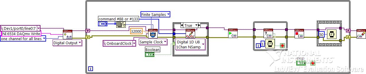
Hello
If I understand the problem you are experiencing, then the reason for the typical behavior when you run the VI, it is that you are not clearing the DAQmx task whenever you intend to go for a fresh DIO write. You stop just the DAQmx task that seems however to clear the buffer on board space.
With this post, I am enclosing a VI of the sample that should work according to your expected behavior. You can even call this VI as a Subvi and can use it to update the DIO port with a digital model of variable length fees. Another fact that I would like to point out, is that, once you have initalised one table, it is not possible to reduce the length of the array. You can only increase by adding new elements. According to your needs given that the digital model that needs to be updated will be of variable length, each time you cll the Subvi, you must create a freash of appropriate length and feed it as input to the Sub - VI. Inside the Subvi, according to the length of this array of entry appropriate buffer space is allocated.
Do trust this solution help solve you the problem, otherwise do not hesitate to go back.
Best regards,
Sagar G yapi | Application engineer | National Instruments - India
Tags: NI Hardware
Similar Questions
-
OR PCI-MIO-16-1 & NI PCI-6070E digital outputs to scb - 68 to the electric circuit
I am designing a circuit and trying to the NI PCI-MIO-16-1 & NI PCI-6070E DAQ from the interface and the SCB-68 to my small circuit. The outputs are 0 (low) to 5 (high) Vcc. I underdstand the NI PCI-MIO-16-1 & NI PCI-6070E are identical regarding the outputs Digital 5 volts? Also the current will be enough to light an LED on a PS2501-4 or an Octocoupler of 4N38? If this is not the case, what I need to do to amplify the current. Or if you have any suggestions on the resistances, capacitiors, etc. Please let me know. Thank you!!
You are right in your way of thinking! From a source of 5 volts, resistance of 500 ohms in series with your LED will provide enough drive in math class of ohm's law you have already provided.
Paul C
-
synchronize NI 9514 with NI 9401 for digital output
Hello
I need to write code to trigger a laser for a PIV system. I use the NI 9514 with training AKD to order a servo. I need to send a + 5V signal to trigger the laser at an angle of rotation of the motor (this is repeated for each turn of the rotor) specific. I also have the NI 9401 DIO. Any idea/example of how to proceed will be much appreciate. I use the scan to the NI 9514 mode, my system is a CRio-9022 with 9114 chassis.
Thank you very much!
According to me, that the example to compare periodic Position is what you are looking for. The description States "shows how to use the output of compare position to generate an output signal to a regular period.
You can find it by going to help > find examples > Input and Output material > Motion Control > NI SoftMotion > properties and methods > advanced.
-
the pci-6238 digital output current
Hello, I referred to the NI 6238/6239 specifications, but I've not seen this specification.
I wonder if the maximum output current is the same as the current (9mA) of entry?You can check this link for the information you need:
http://sine.NI.com/NIPs/CDs/view/p/lang/en/NID/202503 -
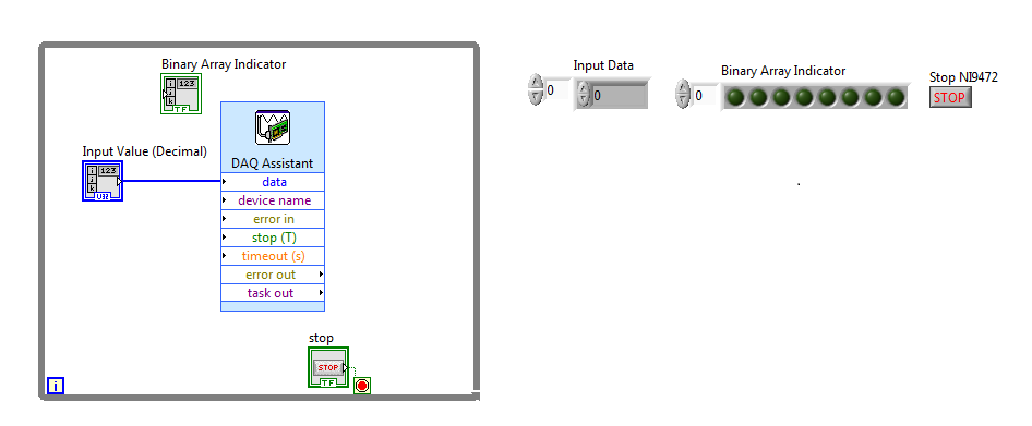
Binary indicator for digital output device
This probably simple question for most people, but there is always a first time to do a new thing/thing we have ever done.
I NI 9472, which is a digital device of the supply, I have no problem to control using LABView to produce the result (line 00000000). I would also like to have some information on the computer screen using the LED matrix. I am able to create a binary table indicator, but fail to connect the decimal point of entry to the binary table.
Please help/provide a few tips, it is appreciated.
Number of table Boolean Boolean palette.
-
Problem with a digital output in the information of an analog input
Hello
I use a SCXI-1000DC module with a module of the SCXI-1600, SCXI-1531 module and SCXI-1163 module to receive an analog of an accelerometer signal and a digital signal.
I claim that the accelerometer is constantly monitored, and the output is on when I want to, by an impulse that I comand in labview.
I use a rate 25 k and a 12, 5K samples per channel on DAQmx Timing.I notice in DAQmx read, if I put a sample of hight by channel, the output is not there when I want to, and if I put a few samples per channel, I exit when I want to, but the program seems to be slow with the passage of time. I don't know how I can solve this problem!
I'm sorry for my English, and I hope you can help me.
Thank you
Silvia
Hello Silvia,.
If you ask a larger number of samples, the labview diagram will stay longer in the DAQmx Read function, so the while loop runs slowly, and the digital output is updated less often.
I suggest that you use 2 separate while loops: one for the analog input and the other for digital output, so that each loop might run at a different speed.
Best regards
-
How can I more easily generate a pulse of digital output of finite length?
Hello
I need to open and close the two pneumatic valves using a TTL output (without load current or the output power) using a PCI-6280 or PCI-6601. The valves must open almost simultaneously and closing after different amounts of time elapsed (millisecond level timing, maybe 100 microseconds-level timing at worst). My current plan is as follows:
-Create a task with two digital outputs (type of waveform) and another task with a counter that generates a frequency set by the user (I know I can use the generator frequencies on one of these cards, but I would have preferred a counter - the best selection of frequencies).
-Wire the output of the counter at the entrance to clock two digital outputs.
-Output of the meter is digitally triggered by another digital channel which I use to control if the pulse goes out. Through its counter node, it is programmed to be redeclenchables.
-Two digital waveforms are drafted who have both consist of unique active high pulse (i.e. signals go ' down (for the amount of time user-defined) - low ".")
-These signals is written to their respective ports and their tasks have started, as is the task of the meter.
-Whenever the user wants to open taps, digital triggering is sent up and then back to low (this can be done with synchronization software, because it is not exactly when the fire valves). Whenever the user wants the valves open for a different period, different digital waveforms are generated and written in the buffers of the digital output channels.
My problem is that it looks like a lot of effort for me to go and I wonder if there is a much simpler solution, that I don't know everything. You can program a computer to produce a pulse of finite length? Is there a faster way to program a digital output for that channel?
Thanks to anyone who responds to their help.
It is certainly instructive. Thank you.
The thing is, I have only six total counters to work with and I have a lot of time to do things. To use these solutions, I would need to use 4 or 6 account counters required to my needs.also that I would need to synchronize their departures.
Overall, I stick to my method for now - less system resources and synchronization can be don by using the same meter of finished output clock and not to use a trigger to all.
Once again, thank you for your help so far.
-
Is it save to use the digital output as a digital input for another channel signal
Hi all
I know it's a stupid question, but I don't have another generator of signals by hand. What I want to know is, can I use the signal digital output of my USB-6001 as an input for the same signal device, but on other digital port? I wasn't directly because I don't want to burn the device...
Thank you
Done all the time. No problems.
-
PCIe-7842R (series R FPGA) digital output does not work properly
Greetings,
I'm having some problem show TTL the correct voltage with my PCIe-7842R FPGA board.
The block diagram of my code FPGA LV Moose appears in "analog - digital .png '. The idea was to convert an analog input (decimal value) to a binary code and 16-bit output by 16 DIO ports. I use the connection block SCB-68 has as the terminal and trendy on the FPGA 1 connector RDIO with SHC68-68-RDIO shielded cable.
The compiled code ok. But during the test, I noticed that some ports has no output TTL levels correctly. For example, for input 1000 decimal, I would expect binary code 0000001111101000. However, some ports (DIO #6, #7, #9, etc.), which are supposed to ~3.3V (1 digital) high TTL output, output actually 0.8V. I have attached the result measured in 'exit digital test.png '.
To ensure that the question was not because of the code of the LV, I did some more tests on DIO #6 with a simple example (simple digital output.png). The output was ~ 1V this time at the digital 1.
It's really confusing because of the digital Edition is supposed to be simple. I used the same FPGA card for controlling roller shutters with TTL signals before and it worked fine.
Does anyone have similar problems? Any suggestions are greatly appreciated.
iron_curtain wrote:
DIOs are connected to a controller digital galvo Cambridge Tech. But I measured the voltage at the terminals of the connector block.
If you unplug the controller galvo DIOs, do they look good (have the right voltages). Do you know how many of these entries to the need for controller? I think you hit the limit the total current available for EID within the Council.
-
Control the Boolean commands and generate a corresponding digital output
Hi all
I'm working on a project of activation of the electrode, here, I thought that how could I order an electrode in a time and generate a digital output of it accordingly. I want to replace it with each electrode with a LED on the front panel and generate a numerical value to each LED on the block diagram.
If it can be divided into two parts
1 control the Boolean outputs
Here, my goal is that if I have 5 leds that are used as a Boolean control, must be ordered so that only one of them lights up at the same time and the rest goes off.
I mean for example if #3 was turned on and that the user pressed the #3 #2 should be turned off and only #2 lights.
2. generate the corresponding numerical value
Depending on the position of the LEDs I want to generate a corresponding numerical value, as previously released 3 coming and exit 2 then comes when the second LED illuminates.I ask all participants to this group to help me with this.
Concerning
Why don't you use the radio button control? You can replace the boxes if you want the buttons.
-
Digital output of 6289 USB to the function generator
Hi ppl.

I have a DAQ USB-6289 card I use M series to interface with a programmable frequency AD 5932 generator (hope it's not breaking all the rules
 )
)In the datasheet of the http://www.analog.com/en/rfif-components/direct-digital-synthesis-dds/ad5932/products/product.html AD5932
It is the interface series (FSYNC, SCLK, SURLABASEDESDONNEESDUFABRICANTDUBALLAST).
I'm using LabVIEW to generate a digital output and help the Council 6289 to send the signal to the ad5932.
The problem is the following:
(1) I am an engineer in chemistry and new LabVIEW and electronics
(2) I don't understand how the digital signal and the FSYNC SCLK and SURLABASEDESDONNEESDUFABRICANTDUBALLAST are related... Sorry for the very basic question...

Hope that's not too much to ask, but if someone could suggest a tutorial or examples it would be EXTREMELLY appreciated...
Thanks for any input because I'm really stuck on this point.
See you soon
You need to find is the complete technical data on the A/D. Who will explain what each of these pins and the time served. It looks like an SPI interface. OR sell the 8451 for this programming. You can or perhaps are not able to use the 6289. I recommend a search of "SPI" to see if anyone has created a VI.
-
How to generate the digital output of the variable duty cycle and clock source being contrary?
I want to generate a digital pulse every front amount of my pulse counters. He must have a variable duty cycle. until now, I've been able to generate a digital output, but I can't change its duty cycle.
pls tell how I should proceed?
Thank you in advance...
-
What is a digital output (DO) good for?
Actually, I wanted to use the outputs digital to move from a 24 VDC circuit (to turn on/off other devices etc.).
But the current output outputs digital is so low that I have even impossible to pass an opto-coupler (opto isolator).
That's why I wonder you use outputs digital for if you cannot use them to change anything?
Of course, I can create a circuit MOSFETS or transistors to switch 24VDC power with the TTL 5V digital output signal. But I guess that most of you do not :-)
And of course, I know that I can buy OR relay modules/cards. In fact, I have many digital outputs available and do not want to buy new modules/cards.
Now, I can test and actually I get 10mA @ 5V on a digital output of NI 9401 (DIO), using the digital output to pass an opto-Coupler.
It seems that the information contained in the data sheet are supposed to mean something else...
-
How to configure the digital output of the pci terjeta 6023E in LabVIEW 8.5?
Hi, I have a card PCI-6023E and LabVIEW 8.5 and I need is to configure the digital output on the card, but did not.
My idea is to get a port of digital data on the map and control by a pwm small dc motor.
I wonder what are the modules with which you can do.Hi skudero,
Probably the web page tracking and the attached example will work.
PWM in software timing using a digital output line
Concerning
Charley - NIB - SR 1368189
-
Manchester in transmission/reception of signals using the digital output of the PCI-6224
How a manchester signal can be sent and received using the OID of the pci card 6224?
I want to create a signal NRZ manchester on a digital output channel and then have the possibility to receive and interpret the same type of signal on a digital input channel.
Any help would be greatly appreciated.
Hi VJohnson,
You might find this post of discussion forum useful.
Looks like LabVIEW has not Manchester coding/decoding built, but do able in your VI by replacing all the elements with the corresponding elements of two and using double the speed of transmission as your clock frequency.
Thank you
Scott M.
Maybe you are looking for
-
My tabs seem strange today with no arrows at the beginning and end to see several tabs.
The appearance of my tabs changed this morning. The green arrows at the end of end of beginning of the line of tabs have disappeared.
-
NB550D - creating an Image and recovery
My laptop is a Toshiba NB550D according to disk management the following is my start-up: Recovery partition Active 1.46 GB7.98 gb main partition224.23 initialization, page file, crash dump, primary assets If I use a disk imaging program like Macrium
-
How to stop Windows Media Player to open all programs. It includes all attempts to stop open.
Even when I click to remove programs windows, Media Player happens. Is this some kind of virus hate by Microsoft to force people to buy other products?
-
Deactivation of the system 50151635
Can help you with this? Thank you!
-
Exporting the problem - Long Edge
Export an image with "Resize to fit: Long Edge ' and 1250 results of pixels in an image of a size 1873 x 1250 pixels! This isn't fair! The long edge should be 1250 pix, no 1873 pix! All the ideas! Using Lightroom CC version 2015.3.