synchronize NI 9514 with NI 9401 for digital output
Hello
I need to write code to trigger a laser for a PIV system. I use the NI 9514 with training AKD to order a servo. I need to send a + 5V signal to trigger the laser at an angle of rotation of the motor (this is repeated for each turn of the rotor) specific. I also have the NI 9401 DIO. Any idea/example of how to proceed will be much appreciate. I use the scan to the NI 9514 mode, my system is a CRio-9022 with 9114 chassis.
Thank you very much!
According to me, that the example to compare periodic Position is what you are looking for. The description States "shows how to use the output of compare position to generate an output signal to a regular period.
You can find it by going to help > find examples > Input and Output material > Motion Control > NI SoftMotion > properties and methods > advanced.
Tags: NI Hardware
Similar Questions
-
6534 PCI for digital output finished generates a continuous output
Hello
I use 6534 PCI for my application, where I generate a digital output, a model finished variable length in a continuous loop. the code runs without error, but I'm not able to justify the behavior of the map. I intend to use the code inside the while loop as a Subvi and if I change the 'command' at the entrance table during each call to the Subvi, the output should vary according to the directives of the entry of the 1 d array.
But this is not the case, the loop displays the previous value that has been given to Scripture DAQmx. If the control panel is changed the output instantly does not change. It takes a while before the actual output changes. The length of the array command I give is also 88 & 133. When I realize that the output is wrong, I disable the DAQmx write vi by a structure of the case, I would expect an error that the output buffer is empty, but rather the old value is generated whenever the start Daqmx vi task is exectuted without.
My tax any problem is that the output buffer is not get replaced with the new value, but I'm specifyng the size of buffer, performing a registration every time and start the task, waiting until the task is done and the task stop. Each stop & writing should delete and empty the buffer, but I did not understad what goes wrong.
Also, I thought that maybe that orders are put in queue up in the output buffer, acual generation is not as fast as the call of the DAQmx write & start, but if that's the case then even if I stop the vi the generation should be until the buffer is empty, but that doent happen VI, break breaks of generation. the number of iterations is equal to the generated models. If anyone can help as to what could be the problem? fi
nd code attached below.
Hello
If I understand the problem you are experiencing, then the reason for the typical behavior when you run the VI, it is that you are not clearing the DAQmx task whenever you intend to go for a fresh DIO write. You stop just the DAQmx task that seems however to clear the buffer on board space.
With this post, I am enclosing a VI of the sample that should work according to your expected behavior. You can even call this VI as a Subvi and can use it to update the DIO port with a digital model of variable length fees. Another fact that I would like to point out, is that, once you have initalised one table, it is not possible to reduce the length of the array. You can only increase by adding new elements. According to your needs given that the digital model that needs to be updated will be of variable length, each time you cll the Subvi, you must create a freash of appropriate length and feed it as input to the Sub - VI. Inside the Subvi, according to the length of this array of entry appropriate buffer space is allocated.
Do trust this solution help solve you the problem, otherwise do not hesitate to go back.
Best regards,
Sagar G yapi | Application engineer | National Instruments - India
-
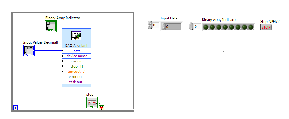
Binary indicator for digital output device
This probably simple question for most people, but there is always a first time to do a new thing/thing we have ever done.
I NI 9472, which is a digital device of the supply, I have no problem to control using LABView to produce the result (line 00000000). I would also like to have some information on the computer screen using the LED matrix. I am able to create a binary table indicator, but fail to connect the decimal point of entry to the binary table.
Please help/provide a few tips, it is appreciated.
Number of table Boolean Boolean palette.
-
Hey guys I'm trying out a file I cut on a plotter. If I watch it 'tracks' mode everything looks good. All the lines are there. If I try and import it into the scalp, he gets all wacked. I had a problem like this once before and I used "expand" in artificial intelligence for him to correct. On this issue when I use 'develop' part of the image disappears (same part that cannot be sen in the tracer software). How can I fix it? "expand appearance" is grayed in HAVE with this file too. Man, I spent a lot of time to get this file done and now it does nothing for me. Thanks in advance.
in case someone else stumbles across this thread, it turns out that it was due to the use of live paint. Once I got it worked (mostly).
-
What is a digital output (DO) good for?
Actually, I wanted to use the outputs digital to move from a 24 VDC circuit (to turn on/off other devices etc.).
But the current output outputs digital is so low that I have even impossible to pass an opto-coupler (opto isolator).
That's why I wonder you use outputs digital for if you cannot use them to change anything?
Of course, I can create a circuit MOSFETS or transistors to switch 24VDC power with the TTL 5V digital output signal. But I guess that most of you do not :-)
And of course, I know that I can buy OR relay modules/cards. In fact, I have many digital outputs available and do not want to buy new modules/cards.
Now, I can test and actually I get 10mA @ 5V on a digital output of NI 9401 (DIO), using the digital output to pass an opto-Coupler.
It seems that the information contained in the data sheet are supposed to mean something else...
-
Problem with a digital output in the information of an analog input
Hello
I use a SCXI-1000DC module with a module of the SCXI-1600, SCXI-1531 module and SCXI-1163 module to receive an analog of an accelerometer signal and a digital signal.
I claim that the accelerometer is constantly monitored, and the output is on when I want to, by an impulse that I comand in labview.
I use a rate 25 k and a 12, 5K samples per channel on DAQmx Timing.I notice in DAQmx read, if I put a sample of hight by channel, the output is not there when I want to, and if I put a few samples per channel, I exit when I want to, but the program seems to be slow with the passage of time. I don't know how I can solve this problem!
I'm sorry for my English, and I hope you can help me.
Thank you
Silvia
Hello Silvia,.
If you ask a larger number of samples, the labview diagram will stay longer in the DAQmx Read function, so the while loop runs slowly, and the digital output is updated less often.
I suggest that you use 2 separate while loops: one for the analog input and the other for digital output, so that each loop might run at a different speed.
Best regards
-
Digital output with NOR-9401 in cDAQ-9174
Hello
I have a cDAQ-9174 with an e/s digital NOR-9401 module. Now I want to output Digital signals on line0:3
$line0: Boolean 1 time = 10ms
Line1: Boolean variable 1 time = 20ms
row2: Boolean variable 1 time = 30ms
line 3:20 pulses (period = 250us, duty ratio = 0.5) after a time = 40ms
the value of line0:3 must be Boolean 0 after 45ms
Can someone let me know what I need to work to solve this please?
Thank you all for your help.
Concerning
Bing
Thank you Christian for your quick replay.
I have some experience in programming of microcontroller with C. I learned LABVIEW for about 1 month and followed a lot of demons in line and tutorials. I know that nodes DAQmx Data Acquisition screws and fundamental property.
As I said at the beginning on the $line0, lin1and line2, they serve to control the relay in my circuit. 10ms could be controlled with the OS clock. Pulse of line3 series is used for IGBT gate signals, which is the critical moment. I want to use the clock machine to accurately control line 3 and synchronize at the same time the pulse with analog inputs from an another two NI9206 modules in the same cDAQ chassis.
I just want to know more on the digital line demand signal relay output and a correlation between the line of analog input-synchronized finished pulse output. Waveform diagram is locked.
Thank you.
Bing
-
Synchronization of analog and digital output with the external sample clock
Hello
First of all sorry for my English, I will try to explain what I want to do.
I want my PCIe-6321 to send two custom signals (modification sawtooths) on a mirror controller. I would also like to generate output with my card at the beginning of each tooth of saw. Everything must be synchronized with an external k-clock signal of 100 kHz. The idea is that whenever the PCI receives a trigger to external clock, it sends two analog output voltages and when he received 1024 clock ticks it will also send a pic of triggering TTL. What I do is first prepare the map and after that in a loop sending and modifing the output values of the two signals and at the same time send a digital signal Boolean in each arch, so when's done it 1024 iterations of the loop I send an event to the digital port. Attached you can see.
The problem is that I don't know how to synchronize both. Can I use the sample clock just to the analog output? I can use sample for the two outputs clock, or do I need to use the output of the meter? If don't know how to use it here.
If I do nothing else bad/wrong, I would be grateful for feedback.
Thanks in advance,
PabloI don't know how but I find the solution. I'm generating more than a positive value (as I was triggered maybe very fast the oscilloscope has been absent there). If I put the sample clock of digital output to use the sampling/ao/Dev1 clock that it doesn't, but if I put to use the same source as the OD (terminal where my external clock is connected), but the trigger to start the DO to be Dev1/ao/StartTrigger this works. I don't really know why, but it does.
Thank you for your patience and your help. I put here the final code.
-
Sampling frequency for digital sampling (cDAQ-9172 & NI 9401)
Hello!
I have a cDAQ-9172 with NI 9401 C-series (digital) module. I would like to taste the digital inputs with a sampling frequency of e.g. 400 or 200 kHz. My problem is that I can only choose a clock 100kHzTimebase and therefore only get a sampling rate of 100 kHz. The 20MHzTimebase clock is too fast, as it gives me a sampling rate of 20 MHz). Is it possible to get a defined user e.g. 200 kHz sampling frequency, dividing for example down the clock of 20MHzTimebase?
Thank you! Last post and this article using the internal one or cDAQ chassis counters has solved my problem.
-
How to synchronize 2 digital output channels that have been created with DAQmxCreateCOPulseChanFreq
Hello
I use peripheral USB6221.
I created two digital output, operating on a frequency of 75KHz and duty cycle of 50%. But I need a period of 1 microsecond between the two channels.
I have craeted the two channel on the same task and guess if I use a delay of 0, the channels will be synchronized, but looking at the scope, the channels are not synchronized. Here's the code I used (I checked also all return codes of coarse and fine).
Thank you
Danny.
Int32 RetCode;
RetCode = DAQmxCreateTask ("", & m_OCtaskHandle);
LogMessage (RetCode, "CreateTask", "");
If (RetCode > = 0)
{
define the first output channel for 1 transmitter (75KHz)
RetCode = DAQmxCreateCOPulseChanFreq (m_OCtaskHandle, "/ Dev1/ctr0", ")
"Transmit1 Line 1", / * name to assign to the channel * /.
DAQmx_Val_Hz, DAQmx_Val_High,
0.0, / * initial delay in seconds * /.
75000.0, / * Freq * /.
0.5 / * market factor * /);
define the second output channel for 1 transmitter (75KHz with 1 microsecond delay)
RetCode = DAQmxCreateCOPulseChanFreq (m_OCtaskHandle, "/ Dev1/ctr1", ")
"Line2 Transmitt1", / * name to assign to the channel * /.
DAQmx_Val_Hz, DAQmx_Val_High,
0,000001, / * initial delay * /.
75000.0, / * Freq * /.
0.5 / * market factor * /);
Describe all channels continuous task
RetCode = DAQmxCfgImplicitTiming (m_OCtaskHandle, DAQmx_Val_ContSamps, 1000 / * I think that NA since continuous * /);RetCode = DAQmxStartTask (m_OCtaskHandle);
Hello Danny,
If you are looking for more output channels of the Digital pulse trains, you can create 1 task of counter that is used as the clock for digital multi-line data output. For this digital task, you will need to make the clock source line PFI for the output of your task of counter. Once this has been done, you will need to create the digital signal for each line of output and write to the card. The example called write dig Chan - Ext Clk will explain how to set up the digital task so that the task has an external clock (the counter). I hope this information helps you and if you have any other questions, feel free to post.
-
Steps to follow:
BB10 device--> settings--> Notifications--> Applications--> [name of your application]--> all alerts [Toggle button]I have an obligation to check whether or not 'All alerts' is allowed through settings when the application is running. To check if we can synchronize permission selected with the settings of operating system Notifications BB10 for my application. How to get javascript code if alerts permission is on / off, while the application is running.
I tried adding the blackberry.system function and tried to hasPermission (blackberry.push) also, I can't determine if permission is allow / prohibit... Please suggest how to get that.
I don't see a WebWorks API for this. If I expected to be anywhere, it's here:
https://developer.BlackBerry.com/HTML5/APIs/beta/BlackBerry.notification.html#jbo1385148829097But it seems that this API has not been fully implemented; It may be useful to connect a developer Issue Tracker JIRA to get this feature added.
At the same time, there is this API of Cascades that looks like what you're looking for:
https://developer.BlackBerry.com/native/reference/Cascades/bb__platform__notificationapplicationsett...Write an extension for this feature should allow you to access this feature:
https://github.com/BlackBerry/WebWorks-community-APIs/tree/master/BB10-Cordova/templateAt the same time, a colleague is currently working on an extension that should open many features of Qt, and I think that the API above should be accessible through this extension. He must be released over the next week or two, so you can wait for that as well.
EDIT: On this last point, see this extension which provides a mechanism for attaching in the majority of the Qt APIs.
https://github.com/BlackBerry/WebWorks-community-APIs/tree/master/BB10-Cordova/QtBridge
-
My client wants ot edit photos and text on its Web site. the site will not be hosted by BusinessCatalyst. Is it possible, and it is possible for me to synchronize the changes with my data?
Hello
Update June 2014 to Muse allows In-Browser editing for Muse sites hosted with third-party providers (not Adobe).
See https://helpx.adobe.com/muse/using/whats-new.html#In-browser%20Editing%20enhancements for more details.
Abhishek
-
Encoder interfaced with NOR-9401
I bought a coder who has open collector and resistance to pull-up 3.3 kohm (TTL) logic output.
The encoder comes with four sons: power + 5V, GND, channel A and channel B. channel A and B are logic output.
Channel A and B are connected to the OID of NOR-9401 which is mounted on the cRIO.
A standard VI for encoder counting is used and compiled under the FPGA environment.
During the measurement, I have observed that there are number of significant loss in both directions encoder.
I don't think that there is a problem with VI like I used it several times on the encoders with output RS422.
Is there a problem with my current encoder with respect to its electrical interface with NOR-9401?
Thank you.
I don't think that there is a problem with pull-up resistance. Even if the digital IO ports have their own resistance to pull-up (usually of the order of 4.7kOhm - should be included in the manual), the power to be handled by the circuit of encoder output transistor is about 2mA. -Check your configuration for a correct connection GND. You must connect the encoder directly power GND to DGND to the printed circuit board Terminal.
-
analog sync of input with the onset of the digital output
I'm trying out an analog signal to a file with a specified frequency samples. I also need a digital output to trigger a measurement at a frequency specified on a separate system. The frequency is controlled by the loop exits and timed when the iteration number divided by the period is exactly a whole number.
Both outputs work. The problem is that they are not synchronized. The analog output amounts to about 0.5 ms faster than the digital signal. (I checked with an oscilloscope) They both start in the 1 ms each loop runs for, but I really need them to start at the same instant. What can I do to synchronize? Also, if I'm going in the wrong direction complete, please indicate.
I use a card PCI-6723, which I think someone at some point, said not having a material sample clock. That's why I try to use a timed software loop.
Hi NEA.
You must use the 6723's built-in calendar to accomplish what you want. As the digital output subsystem is only clocked by the software, an appropriate solution should be to use one of the counters to the pulse output.
The attached code should show how. You can use the counter to output a pulse all samples of the AO N task. Material requires the initial delay to have a minimum of 2 ticks, so the meter will be behind the task of the AO by 2 samples in this case. There are different ways to work around this problem if you need (for example write two samples of 0 first).
Best regards
-
How to synchronize the device with an analog input device?
Is it possible to synchronize a device (e.g. Basler scA640-70fm, IEEE 1394 b or NI 1722 smart camera) with an input device analog (for example, NI PCI/USB-6225 or NI PCI/USB-6255)? For example, it is important to a video image of match with a sample of data digitized by the A/D converter. In particular, it is important to know when the first video image starts compared to samples of digital data. If it is possible to synchronize the camera with the A/D device, then then how is it?
Thank you
Ian
Hello Robert,.
Thank you for reference and information.
Ian
![http://s283.photobucket.com/user/IPTalaska/media/Airbrushing%20forums/Logo-mishap_zpsf2662 e11.jpg.html] [IMG] http://i283.photobucket.com/albums/kk319/IPTalaska/Airbrushing%20forums/ Logo-mishap_zpsf2662e11.jpg[/IMG][/URL](http://s283.photobucket.com/user/IPTalaska/media/Airbrushing%20forums/Logo-mishap_zpsf2662e11.jpg.html][IMG]http://i283.photobucket.com/albums/kk319/IPTalaska/Airbrushing%20forums/Logo-mishap_zpsf2662e11.jpg[/IMG][/URL)
![http://s283.photobucket.com/user/IPTalaska/media/Airbrushing%20forums/Logo-mishap-2_zpsf56 dfd30.jpg.html] [IMG] http://i283.photobucket.com/albums/kk319/IPTalaska/Airbrushing%20forum s/Logo-mishap-2_zpsf56dfd30.jpg[/IMG][/URL](http://s283.photobucket.com/user/IPTalaska/media/Airbrushing%20forums/Logo-mishap-2_zpsf56dfd30.jpg.html][IMG]http://i283.photobucket.com/albums/kk319/IPTalaska/Airbrushing%20forums/Logo-mishap-2_zpsf56dfd30.jpg[/IMG][/URL)
Maybe you are looking for
-
When I print an email from Yahoo, the text wraps not (it was) then part of the text is cut off. In addition, the sidebar my Inbox, sent, drafts, etc. the list is printed with enamel - it has not used to and because of that there is not enough room fo
-
Problem with putting satellite Pro 6000 switch
In recent weeks, I have a problem with my laptop to start. With the battery or not, the situation seems to be the same. Even when I remove the battery and plug in DC. Then the Green led DC lights, but pressing the button does not turn on the laptop.
-
Documents Passport blackBerry go Passport
I want to know if passport has Blackberry to a version full of Documents to Go or not? It supports create new worksheet Excel in Document to Go or just change please notify
-
How to simulate the Q10 device?
Hi, is it simulator can be used to simulate the Q10 device (with keyboard)? Thank you
-
How to handle the end makes arriving in OWB
Hello everyoneI have a table of facts related to a dimension with SCD type2. My problem comes when I files in fact arrive late (a few documents that belong to the past are coming now and I have to connect them to records in dimension to this date in