Acceleration in the frequency domain
Hello
I enclose a vi that I already modified the existing example. I will use this vi to measure pressures (pressure sensor) and acceleration (from an IEPE accelerometer). Each of the two sensors is connected to a housed in a chassis CompactDAQ C Series module connector 4. The pressure sensor measures the pressure of the water flowing in a pipe while the accelerometer will simultaneously measure the vibration of this pipeline caused by the fluctuation of water pressure. In this vi, I am connecting a signal of pressure and acceleration TDMS file and then read the two signals on the cards of distinct waveform. The acceleration signal is written and read in the time domain. I need your help to make change more on this vi to take the acceleration signal and read on a separate table in the field frequency and written also the frequency of the field values in a file of PDM. After this change, the vi is supposed to have three graphics of waveform (pressure, acceleration time-domain and acceleration in the frequency domain and opens two tdms files, one for pressure and acceleration in the time domain and one for acceleration in frequency domain.)
I tried many ways all failed because I'm not very familiar with the measurements of vibrations.
I thank in advance.
Hello
It is important that you should decide if the frequency data you are interested in are constants based on time, or if you need to know how the data of frequency changes over time.
For constant frequency over time, take a look at the Fast Fourier Transform: http://www.ni.com/white-paper/4541/en/
If you need to know how the frequency display, take a look at the analysis of the frequency of the common time: http://www.ni.com/white-paper/3548/en/
Tags: NI Software
Similar Questions
-
How to detect the peak frequencies in the frequency domain?
Hello
I built a small test consisting of two sine waves of varying frequencies, program it is and subsequently FFT is performed on it to find the frequencies of two peaks. I tried to display the values of these two frequencies somehow, but I can't find a way.
I searched the forum before asking the question, many of them suggested using extract more Information VI tone I tried and could not get any results.
I have attached to my account. Please take a look. If you know all the discussions on the forum directly related to my problem, please just cite it.
Thank you
LD
Don't wire the tone of several extracts the wire coming from the Express VI of Sprectral. You need to run on the thread after that the two signals are summed.
-
How ro provide Convolution in the frequency domain
Hello world
I have a problem with application a convolution of the image and kernel smoothing in LabView. The idea behind this is that convolution is a multiplication by the area of the Fourier transform. So firstly I want to apply convolution by standart IMAQ convoluted VI, then, to do essentially the same thing, but do it manually FFT of the image and the kernel and then their multiplication by then apply inverse fourier transform and observe the resulting image. Finally, I get two different results, but they should be the same, I can't get the idea why.
-
Filter of time domain frequency domain filter
Hello
I am applying the weighting filtering of an audio signal.
I'm to draw the response of the filter in the frequency domain.
How can I turn this into a time domain filter and use it with a real audio signal?
In theory, it's pretty simple. You take the s-domain transfer function and apply the bilinear transform. After a few edits, you can extract the coefficients 'food for animals-descendant' as well as the coefficients "feed-forward". These coefficients can serve as input of the filter of Labview functions. As I said, the theory is simple, but I think it will be a tough job to do this. Weighting is used in the measurements of the sound level, to mimic the curve of the human ear. If you plan to use spectral analysis in your application, you can skip the filter and apply your formula for your spectrum frequency bins. In this way, you can save a lot of work, because you stay all the time in the frequency domain.
-
Error to find the frequency of signal to tachometer
I use the vi "Extract only your Information" to find the speed of a motor. The entrance is a monarch Laser Tach AC output. Tach reading is very regular and the AC output is 5 volts peak. There are a few negative pics, but these are at the speed of the engine. My output frequency, who should read the changes back from 1800 1800 at a frequency near 5400, but not exactly 5400 (5321, etc.). Y does it have no signal conditioning that I'm missing before signal to the vi "extract", for example, the window it and then use the frequency domain cutting-edge research?
Thanks in advance,
Ron
Matt,
Just to let you know that I put a bandpass filter in my vi. I took the input of the speed estimated of the user and put in parentheses of the bandpass filter to be 25% below 25% above the target and the input of speed tachometer works very well!
Ron
-
When I click on an address, instead of the name of domain appearing in the url field, only the IP address appears. How can I get the real domain to pop?
Start Firefox in Firefox to solve the issues in Safe Mode to check if one of the extensions or if hardware acceleration is the cause of the problem (switch to the DEFAULT theme: Firefox/tools > Modules > appearance/themes).
- Makes no changes on the start safe mode window.
- https://support.Mozilla.org/KB/safe+mode
You can attach a screenshot?
Use a type of compressed as PNG or JPG image to save the screenshot and make sure that you do not exceed the maximum file size (1 MB).
-
Questions about the frequency step response
Hello
I use the Signal Express 3.0. I'm not clear on the transfer functions in step of frequency response with different modes of calculation of the average. What I got from the help file is this H (f) = Sab (f) /Saa (f) which is cross the frequencies on the spectrum auto where is the pulse and b the signal response signal. When the mean quadratic value is used, I wonder if the transfer function becomes greatness of cross spectrum divided by the magnitude of the spectrum of the car. When an average of vector is, everthing is used in complex numbers. He averaged temporal signals, frequency domain signals, or the results of transfer functions?
Thank you very much.
The algorithm to calculate the spectrum is the same in both modes. However, the method of calculation of the average can have a huge impact on the outcome. Mean quadratic value is performed on the spectrum itself, after the calculation. Vector averaging is done on the input signals before the calculation. With an average of vector signals must be consistent (have the same phase) or the result will be bad due to the signal being on average by far.
-
The amplitude of the frequency. Bode CD. State space
Hi all
Gently, I have a simple model that gives me a Bode phase and magnitude, using the block 'CD Bode'. AFAIK, this block takes the representation of the State space and assesses the frequency and scale of the system.
Can I change the value of the Phase or amplitude Bode? by means change the input signal that bode uses to evaluate the response of the State space?
Note: The entry, I want to say here is the value of the sinusoidal signal that Bode uses to give the phase and the amplitude of the State space.
Thank you
The works of Bode CD functions as a "sweep" of all frequencies and who you are. The algorithm is not a frequency controlled, he comes back the entire spectrum. You can't just get a specific frequency. However, if you use the fuction 'Assess frequency of CD', you can provide the model and frequency, and this will give you the specific Mag/Phase for this frequency. This example shows how to do this in LabVIEW:
C:\Program Files (x 86) \National Instruments\LabVIEW 2014\examples\Control and Simulation\Control Design\Time Analysis\CDEx Lin Simulation and stable State.vi
Now, if you want to 'form' your frequency, so you can create another model, connect with each other and try to change the output frequency. This example shows how to do this:
C:\Program Files (x 86) \National Instruments\LabVIEW 2014\examples\Control and Simulation\Control Design\Frequency Analysis\CDEx frequency analysis
If you just want to "simulate" the response of the signal to a specific sine wave, then you will need to you another function in the time domain palette called "linear Simulation CD. With this, you can generate a specific sine wave and you can see his behavior in the time domain. Here is an example:
C:\Program Files (x 86) \National Instruments\LabVIEW 2014\examples\Control and Simulation\Control Design\Time Analysis\CDEx sine wave with Mathscript.vi
Hope this helps,
-
determination of the sampling rate and the frequency waveform data record
Hello
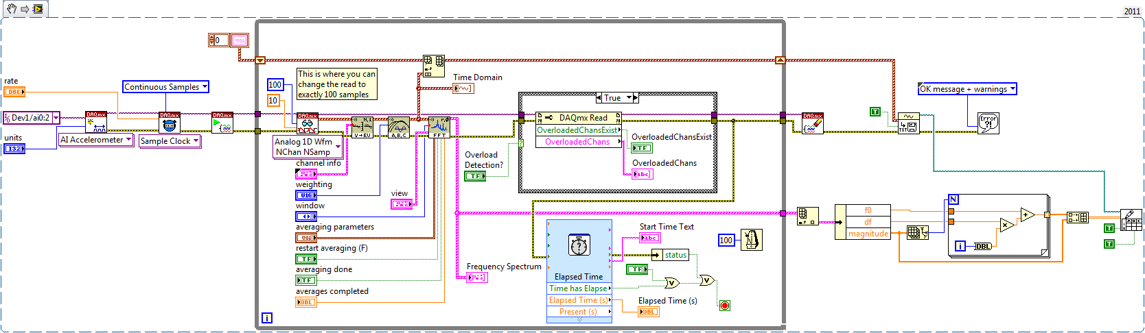
I write a simple program that collect data from a triaxial accelerometer input, convert it to a frequency spectrum, and then save the time domain and the frequency of the waveforms in an external file separated. I don't understand how to set the sampling frequency, however. On the DAQ Assistant, I updated the acquisition mode "Samples continues" and read samples is 2 k, which corresponds to the total number of data points that are collected. How can I program sampling for awhile, it 30 seconds, for example? Wouldn't be better to set up a trigger, as it will continue to collect data up to what I told it to stop?
I also want to save waveform data in a separate file that can be easily seen by other computers that have not installed Labview. I have currently the program put in place to convert a text string of the waveform of the time domain and then save it in a text file or a spreadsheet. It works fine, but I would also like to record the frequency wave, which is a different type of data. How can I do this or is there a better way?
My program is attached. Thanks for your help!
Here's how you can use the shift register to build the table, and also where you can choose to play exactly 100 samples per while the loop iteration.
Brian
-
Get the frequency of a graph in real time of the waveform trace
Hello
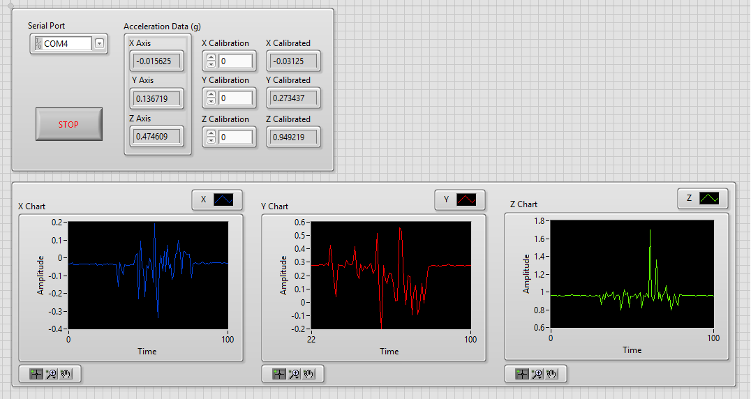
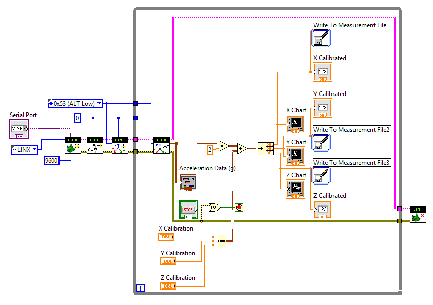
I want to get the frequency of the graphics path in real time. The data comes from a connected to an Arduino UNO ADXL345. I use LINX to read data.
I separated given x, y, z in order to plot separately and later to get their respective frequencies as well.
Here is an excerpt of my VI as well as the front panel.
I used a the Measurment file for each axes entry so I have a copy of the data.
Before posting, I tried the LabView Spectral tutorial first. But it's different from what I want to happen because you know the exact frequency in this tutorial.
I have also attached my VI.
Thank you!

If all you want is to know the spectral content of a signal in the time domain, there are a number of examples show how to do it. I would start by looking at the functions of the FFT.
Mike...
-
CPU runs at half the frequency in Satellite
Not sure if it is a problem, but the CPU runs at half the frequency. I put the high performance plan and still the same. I think it should work at full power.
I also tried to disable the CPU power option in the BIOS and nothing helped.
To monitor the use CPU - Z and Speccy.What you think about this?
Is it normal?Hello
The Intel CPU supports the Intel Turbo Boost technology
Dynamically, this Intel Turbo Boost technology increases the frequency of the processor as needed by taking advantage of thermal and power margin to give a burst of speed when you need it and increase energy efficiency when you don t.The CPU also supports Enhanced Intel SpeedStep technology
Enhanced Intel SpeedStep technology is a means of which allows high performance while meeting the needs of conservation of energy of advanced mobile systems. Conventional Intel SpeedStep® Technology puts both voltage and frequency in tandem between high and low levels in response to the processor load. Enhanced Intel SpeedStep® technology is based on this architecture using design strategies such as the separation between the voltage and the frequency changes and clock partitioning and recovery.
-
Satellite P300 - 23L - adjusts the frequency of the music
Hey, recently bought a toshiba p300 - 23L.
Listening to my music through speakers the impressive laptop I noticed that the laptop seems to set the frequency of the music according to the high and low points of a song? I can see why this was presented as a function, but it made my ears go funny and I don't like.
Can someone tell me if I can disable this option at all, and if so, where, I do this.
Other than the laptop has an audio system coming out, just like shame it varies throughout each song!
Thank you all,
Martin
Hello
Are you sure that the music files are not reported in the different volume levels.
From my experience, no all songs have the same volume level.
My MP3 don t even support files volume most of the files are differentTo be honest I have never heard that the laptop would control automatically the volume level according to each song
However, the P300 should contain an Audio chip (can be found in Control Panel).
Check that maybe you can change some parameters here.Welcome them
Jimi -
Satellite L30-134: is it possible to determine the frequency of 533 MHz RAM?
Hello!
I have Satellite L30-134 and used a module of 1 GB / 667 MHz (sic!) for a while. Same Toshiba says maximum speed 533 MHz memory he recognizes module PC-5300 and sets exactly to 667 MHz.
I decided to increase the RAM and bought another PC-5300 1 GB stick.
... RAM is only 1 GB with two modules together. The two sticks are OK - L30 sees 1 GB and works well with each of them separately.I know that the reason is that Toshiba couldn't work with greater speed on the two banks (or something like that).
So. It seems to be a good idea to set the frequency of 533 MHz and it should work.
The only question is to know how to do it? BIOS Setup is almost empty and does not have these settings.One advise, please (except to buy sticks more :)
Hello
Laptop Satellite L30-134 is a processor 1.5 GHz of Intel-Celeron-M (Yonah).
Is this good?This processor supports a 533 Mhz bus and if you use modules of 533 Mhz RAM then will automatically solve this value!
Simply put, you do not need to change anything manually! Everything is controlled automatically.Concerning
-
How to operate continuously the ' frequency with digitizer step-down converter external vi "?
Hello
I use SMU-5663 on SMU-1075 chassis. My goal is to use "step-down with digitizer external .vi" in order to run the SMU-6901 frequency continuous step-down converter. To do this, I added a while loop to the provided sample (see file attachment). The problem is that the while loop does not change; the program stops as soon as its launch.
Is there anyone who can help me with this you problem?Hello
The 'get frequency response' VI aims to help correct the answer of the step-down in the acquired data. The response of the step-down changes only with frequency and reference level. In your VI, you are in a loop when you call 'Get frequency response' but do not change the frequency or level baseline for the release of the VI will not change.
To use the external digitizer, you want to adjust the center frequency and level in DAMA reference, read the frequency response and frequency step-down converter win in DAMA, to acquire data starting from the external digitizer and correct using the frequency response of the step-down, and win. You can loop through the acquisition and treatment portions until you change the central frequency or reference level.
-
Calculation of the frequency of real output of a PXI-5402
I have a card PXI-5402, sitting in a high chassis. I'm only interested in the sine wave output at frequencies up to about 10 kHz. I know that it is possible to request an output frequency and then interrogate the acutal output frequency but I prefer to be able to calculate before hand. All I can find in the literature is a figure of 0.355uHz for the frequency resolution.
Is there a better description of the frequency resolution? If this is not the case, the resolution is exactly 0.355uHz or is it an approximation (to 3 significant digits)?
This webcast is a great way to learn the process including the NI 5402 5406 OR exploit to generate periodic duty: http://www.ni.com/webcast/75/en/
The 0.355uHz value is a theoretical value of the frequency rate achievable depending on the size of the accumulator Phase and clock frequency. It's the closest thing I can find on ni.com that you can use to calculate the value: http://zone.ni.com/reference/en-XX/help/370524R-01/siggenhelp/ni_5401_11_31_frequency_resolution_and...
According to me, Fc for the NI 5402/5406 must be 100M and the size of the accumulator is 48 bits. Frequency resolution so = Fc / 2N = (100 × 10 ^ 6) / 2 ^ 48 = 3.55271368e - 7
Keep in mind that the device has a VCXO frequency accuracy specification of + / 25ppm, if you have no PLL block him to a better source.
Maybe you are looking for
-
HP Pavillion PC AIO 23: hard drive
I have a PC HP Pavilion AIO 23, and I need to replace the HD, preferably with a similar one. Is someone can you please advise me what is the model number for this HD, or brand name, size and other details that I should look out for. Thank you.
-
BlackBerry Smartphones first vs password synchronization
Hi, a problem during the first synchronization bbInformations / BB9800 torch. the password is recognized and accepted by the BB, but the same password entered for the BBS terminal is denied. I have 10 attempts, fortunately I can start over again by t
-
How to do old msn homepage back, the news is really bad!
How can I get the old msn home page, the news is really bad!
-
Limits of size of the unit mailbox and filtering
Is there a size max / recommended for a unified messaging environment? I heard that for a 100 MB size limit? The unit still filter through the Inbox for a new message or just when you have saved messages of all types such as e-mail, fax, vm? I don't
-
Customer remote VPN cannot ping certain IP
My Cisco VPN client can establish the tunnel with my successful ASA5505 Office vpn but cannot ping some IP such as an internal server (10.100.194.6). FIREWALL-1 # ping 10.100.194.6Type to abort escape sequence.Send 5, echoes ICMP 100 bytes to 10.100.