Acquisition mode continues for USB-5132
Basically, we like to use USB-5132 for recover data from two input channels digitizer continuous (I / Q signals).
I perform ^ 2 + Q ^ 2 operation continuously in Labview and then export the result in real-time to
C / C + c++ / Matlab on PC data format for more complicated algorithms of signal processing.
Is this possible?
Thank you very much for all your comments!
Gators,
Any device that you can find in the PCI form factor that is able to acquire quickly enough for your application will work for you. The material has nothing to do with your ability to process and display data on the fly. How to write your program to acquire and process data will be the determinant of whether you will be able to track the incoming data. I would recommend that you look for in producer / consumer performs a loop to process the data. The PCI-5102 will not be able to acquire fast enough for your application, I recommend the PCI-5114 or PCI-5112 for your application. I also recommend to take a lot of memory board for the card you purchase as you go to acquiring data at a fast speed for a long Aussie time.
Tags: NI Products
Similar Questions
-
external reference for USB-5132
Hello
I have a few questions (I hope) General on the use of an external reference on our USB-5132 digitizer clock. We want to block for the other oscillators in our system, which are currently locked to a single reference of 10 MHz. If I connect our reference of 10 MHz at the entrance of PFI1, my questions are:
1 is now locked 5132 to our system? Or, is it necessary to specify in the installation software we want to replace the internal reference of the 5132 and rely entirely our external reference?
2. in order to have the best possible of locking, do we need to tell the 5132 sample at a frequency which is divisible by 10 MHz (for example 20 MHz, 10 MHz, 5 MHz, 2 MHz, etc.)? Similarly, we are worse off if you want to try to say, 13 MHz?
Thanks for any thoughts.
Best regards
Penny
Hi Penny,
You need all three. The ' sampleScopeSession.Timing.SampleClockTimebaseRate = 1.0e7; "is the Source of SampleClockTimebase rate. The only piece of code that you won't need is the 'sampleScopeSession.Timing.SampleClockTimebaseMultiplier' because your device does not support RIS.
Kind regards
Izzy O.
Technical sales engineer
National Instruments
-
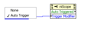
I have a few USB - 5132 s that I am incorporating in montages of test which will be controlled by LabView application basically, I need them to run in auto trigger mode, just like a standard of digitization "scope. By that I mean to set a threshold and use trigger dashboard, but in auto mode. In this case the ' scope retriggers continuously, and when there is a real trigger event, the display syncs upward. " So if you have the game to relax in the center of the screen position, edges that meet the trigger criteria align to Center; Otherwise, the signal is displayed without taking into account this kind of alignment.
The NO-SCOPE Soft Front Panel application can do that, then I know it's possible. But I can't sort out how to make myself in LabView. One thought I had was to pretend: essentially set up to trigger normal edge and in the case of a timeout, then simply use a software to obtain new data and update the display. But I do not know how to set the timeout to trigger.
Any ideas? Thank you.
Andy,
There is a NO-Scope property that you can use to allow automatic release. The property is called trigger modifier, and it has two possible values: None (normal trigger) or Auto-Trigger. Also, there is a property that is read-only called automatic activation, which will tell you if an acquisition was triggered automatically or if a real relaxation has been received.
-Christina
-
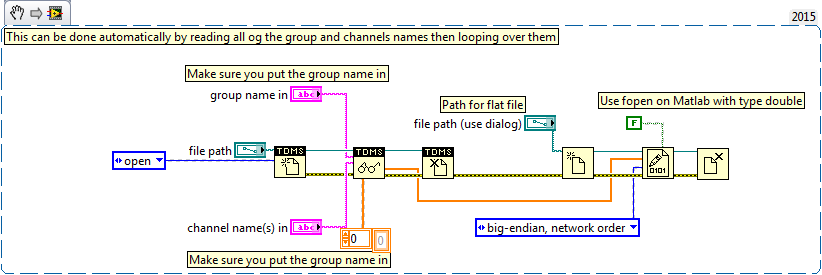
Writing data to extend the acquisition of data for the sampling rate high file
These are the tasks that I have to do to take noise measurements:
(1) take continuous data to USB 6281 Office, in a sample of 500 k (50 k samples at a time) rate.
(2) save data continuously for 3 to 6 hours in any file (any format is OK but I need to save in a series of files rather than the single file). I want to start writing again file after every 2 min.
I enclose my VI and pictures of my setup of the task. I can measure and write data to the file continuously for 15 minutes. After that, I see these errors:
(1) acquisition of equipment can't keep up with the software (something like that, also with a proposal to increase the size of the buffer...)
(2) memory is full.
Please help make my VI effective and correct. I suggest to remove him "write in the action file" loop of consumption because it takes a long time to open and close a file in a loop. You can suggest me to open the file outside the loop and write inside the loop. But I want to save my data in the new file, after every 2 min or some samples. If this can be done efficiently without using Scripture in the measurement file then please let me know.
Thank you in advance.
This example here is for a single file and a channel, you should be able to loop over that automatically. The background commentary should be the name of the channel, no group namede the name of the channel in the control.
-
Real-time display at the high frequency of data acquisition with continuous recording
Hi all
I encountered a problem and you need help.
I collect tensions and corresponding currents via a card PCI-6221. While acquiriing data, I would like to see the values on a XY graph, so that I can also check current vs only voltage/current / time. In addition, data should be recorded on the acquisition.
First, I create hannels to analog input with the Virutal DAQmx channel create, then I set the sampling frequency and the mode and begin the tasks. The DAQmx.Read is placed in a while loop. Because of the high noise to signal, I want to average for example every 200 points of the current and acquired for this draw versus the average acquisition time or average voltage. The recording of the data should also appear in the while loop.
The first thing, I thought, was to run in continuous Mode data acquisition and utilization for example 10 k s/s sampling frequency. The DAQmx.Read is set to 1 D Wfm N Chan N Samp (there are 4 channels in total) and the number of samples per channel for example is 1000 to avoid the errors/subscribe for more of the buffer. Each of these packages of 1000 samples should be separatet (I use Index Array at the moment). After gaining separate waveforms out of table 1 d of waveforms, I extracted the value of Y to get items of waveform. The error that results must then be treated to get average values.
But how to get these averages without delaying my code?
My idea/concern is this: I've read 1000 samples after about 0.1 s. These then are divded into single waveforms, time information are subtracted, a sort of loop to sprawl is used (I don't know how this exactly), the data are transferred to a XY Chart and saved to a .dat file. After all that's happened (I hope I understood correctly the flow of data within a while loop), the code in the while loop again then 1000 samples read and are processed.
But if the treatment was too long the DAQmx.Read runs too late and cycle to cycle, reading buffer behind the generation of data on the card PCI-6221.
This concern is reasonable? And how can I get around this? Does anyone know a way to average and save the data?
I mean, the first thing that I would consider increasing the number of samples per channel, but this also increases the duration of the data processing.
The other question is on the calendar. If I understand correctly, the timestamp is generated once when the task starts (with the DAQmxStartTask) and the time difference betweeen the datapoints is then computed by 1 divded by the sampling frequency. However, if the treatment takes considerable time, how can I make sure, that this error does not accumulate?
I'm sorry for the long plain text!
You can find my attached example-vi(only to show roughly what I was thinking, I know there are two averaging-functions and the rate are not correctly set now).
Best wishes and thank you in advance,
MR. KSE
PS: I should add: imagine the acquisition of data running on a really old and slow PC, for example a Pentium III.
PPS: I do not know why, but I can't reach my vi...
-
All,
I try to use NI USB-5132 Digitizer. Looking through the material on downloads, it seems that I have NEITHER-SCOPE using this product; I therefore downloaded NO-SCOPE 3.9.7 and tried to install only to find the following error message:
"Version not supported NI-detected VISA
A version of NI-VISA, which is not supported on this operating system has been detected. You must cancel this installation and uninstall the old version before continuing. Visit ni.com/frinfo and enter the Info Code CleanVista for more information. »So I followed the instructions and it says I need to uninstall the software OR... I would just install another version of NI-VISA instead reinstall waste products OR I have. No one knows the version of NI-VISA used by NO-SCOPE 3.9.7 or where to find this information? I am using windows 7 32-bit, LabVIEW 2011 SP1.
-Bill
Greetings,
I find that the typical reason users come to this error message is an upgrade of the operating system. When our Setup program detects that a version of our software which is not supported on the current version of the operating system is installed there don't try to remove it and provides instead that error. This can happen if, say, a user upgrade Windows XP to Windows 7 without performing a clean install of the operating system. The simplest solution:
- Go to the control panel
- Select Add/Remove programs
- Choose National Instruments software
- Remove NI-VISA.
- Install a new modern version of NI-VISA.
With the outdated critical version removed safely, modern Setup will work fine.
Thank you
James Duvall
-
Mode script for ANY c ++ function
Hi all
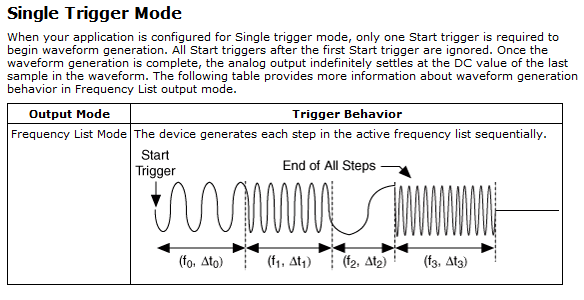
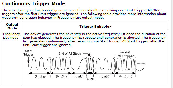
My goal was to use the pxi 5406 to implement features of frequency sweep. Right now, we use only the functions on the list of the frequencies of creation. There are four modes of release for the frequency list, signle, continuous, step by step and burst. We use the bleachers through fashion. It is painful to use this mode, since for each frequency, you need to send a rising edge, so if I have several hundred, it means I have to produce this amount of rising edges. This will generate a lot of buffer in another analog card.
My question is, could I use script for the frequency list view? Or is there a smart way to achieve this? From the file of signal aid, he said that there are some c programe on script mode. But I can't find any examples in my computer. If you have any other, could you send me?
Thank you very much.
.Yami.
Yami,
The 5406 has the ability to run script mode. Only for her output modes are Standard function and frequency list. However, I believe that you can do what you want to do with the list mode frequencies. Assuming that you do not want to trigger you can put the camera in single or continuous Mode. Single will play your select frequency scan and then once completed, build:
Continuous is similar, but you continue to repeat the signals to stop:
All the above details are in aid of signal generators of NOR. I looked under the heading devices > 5406 > trigger > triggering Modes.
With simple or continuous, you can specify the length of the waveform step, which could be a good starting point. With regard to the examples for c ++, I do not have, but if you look in the Start Menu, NOR-FGEN, National Instruments, examples, OR-FGEN C examples you can find a folder for "Sweep generator", there is a model and an example C you can look over your program after. I hope this helps!
-
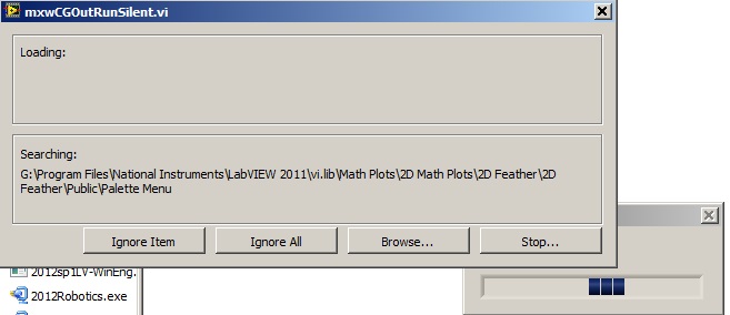
Acquisition of data NOR usb 6008: a strange problem: mxwcgoutrunsilent.VI is not respected
Expensive OR
Today, I bought an acquisition of data NOR usb 6008
and I'm using labview in 2011
the problem is appear when after I end the process of configuration of the i/o data acquisition Wizardthe following image shows the mxwcgoutrunsilent.VI is ignored and an error has occurred
someone can help provide this VI for me
What is the complete labview modules can also so I could do a real time data acquisition
Best regards
mangood,
You received an error code? If so, what is it? What version of NOR-DAQmx driver you have installed? It seems your driver potentially incorrectly installed, and you may need to reinstall the driver.
Here is the link to the latest version of the NOR-DAQmx driver: http://www.ni.com/download/ni-daqmx-9.8/4297/en/
-
Synchronization of two SMU 6537 in acquisition mode
Hello
I need to use two SMU 6537 in parallel for a digital acquisition, their examples of clock is synchronized and running at 50 MHz. In the manual, I can't know is possible to correctly route connections through PXI background:
-It seems that the path available only for export SAMPLING CLOCK in acquisition mode is 5 PFI, so no way to settle the two cards in a master-slave via the background.
-I don't see or can use the background 10 MHz REFERENCE for synchronization, because it seems impossible through the DAQmx driver to deliver this line as input for the time base and trigger (it is not even in the list of possible signal entries).
-The manual States that the maximum allowed value for an external time base is 50 MHz, whereas I need 50 MHz acquisition rate. I guess I should put in Sync synchronize databases internal time of the two councils through the background, but I can't figure out how.
Any suggestion on how to solve this problem?
Thank you, Piero.
Piero,
TO synchronize these cards, you must share the sample clock and a start trigger. You should be able to send the sample for PXI Trig 7 line clock and use it for each of them.
-Christina
-
acquisition of continuous sample with multiple channels
Hello! Please tell me what I'm doing wrong here, I'm confused about how the acquisition of continuous sample with several channels (using NI USB-6215 boxes).
Following code is python code, but I don't know who confuse you
 (and it's only a part of my code in order to not try, it won't work
buffer_size = 2000 #samples to read
sampling_rate_hz = 20000
channels = "Dev1/ai0 ai1/Dev1" #this can be a string or a large number...CHK (nidaq. DAQmxCreateTask ("", ctypes.byref (taskHandle)))
CHK (nidaq. DAQmxCreateAIVoltageChan (taskHandle, channels,"", DAQmx_Val_Cfg_Default, float64(-10.0), float64 (10.0), DAQmx_Val_Volts, None "))
CHK (nidaq. DAQmxCfgSampClkTiming (taskHandle,"", float64 (sampling_rate_hz), DAQmx_Val_Rising, DAQmx_Val_ContSamps, uInt64 (buffer_size) "))
CHK (nidaq. DAQmxRegisterEveryNSamplesEvent (taskHandle, DAQmx_Val_Acquired_Into_Buffer, uInt32 (1000), uInt32 (0), EveryNCallback_func, None))
CHK (nidaq. DAQmxRegisterDoneEvent (taskHandle, uInt32 (0), DoneCallback_func, None))
the callback function #and
def py_EveryNCallback_func (self, taskHandle, event_type, nSamples):
data = numpy.zeros ((self.channel_amount,buffer_size,), dtype = numpy.float64)
read = int32()
CHK (nidaq. DAQmxReadAnalogF64 (taskHandle, buffer_size, float64 (10.0), DAQmx_Val_GroupByScanNumber, data.ctypes.data, buffer_size * number_of_channels, ctypes.byref (read), None))With only one channel, everything's fine, and tension diagram looks like this:

buffer_size = 2000, sampling_rate_hz = 20000
But if I use two channels, voltage diagram looks like this

buffer_size = 2000, sampling_rate_hz = 20000
It looks like the sampling rate is higher or there are fewer values?, but with two channels with the results table is 2000 * 2 long and with a single result is 2000 * 1 long is not smaller
most of the settings important (?) in my code:
DAQmxCfgSampClkTiming "float64 rate": 20000 (sampling_rate_hz)
'UInt64 sampsPerChanToAcquire' DAQmxCfgSampClkTiming: 2000 (buffer_size)
DAQmxRegisterEveryNSamplesEvent "uInt32 nSamples": 1000 (?)
'Int32 numSampsPerChan' DAQmxReadAnalogF64: 2000 (buffer_size)
DAQmxReadAnalogF64 "float64 [] readArray": [[buffer_size] * number_of_channels]
'UInt32 arraySizeInSamps' DAQmxReadAnalogF64: buffer_size * number_of_channelsas you can see nSamples is a big question mark, but the problem still exists if I set variable buffer_size y (2000)
Hi Dazzler,
It is not a multi-channel example that ships with the driver, but after a quick look at the code that you use in your third post, everything seems to be configured correctly. The only thing I was thing I got a question about your plots. Looks like you draw each time the same number of points. If you draw just the table of data directly from the playback feature, you need to draw (buffer_size * number_of_channels) number of channels since the data returned is as an interlaced array. You can also choose to deinterleave samples. More information about this lie in the NOR-DAQmx C reference help, which is installed with the NOR-DAQmx driver.
Kind regards
Kent
Technical sales engineer
-
several webcams in for usb or imaq vision Builder
Hello
I have a question about imaq nor for usb or vision builder AI 3.6 (I did a vi with imaq and I run in the constructor of the vision) and I want to know how can I connect multiple webcams to the computer, and how many of them can be connected. can they all be of a make and model and can they be executed with a driver installed on the computer?
Thank you
Hello
In general NOR-IMAQ for USB can support only one camera at a time. You can acquire multiple cameras (not simultaneously) using USB IMAQ list VI cameras to identify each device plugged into your system and access it via the other IMAQ live to USB.
I would also like to point out that Vision Builder AI does not support the NO-IMAQ for cameras USB driver. It is designed to solve machine vision applications, but USB cameras provide in general or advanced necessary for machine vision triggering modes. Because the machine vision and USB cameras will usually together, we do support USB cameras in Vision Builder AI.
-
People-
I just USB-5132 / s, trying to use NO-Scope in BT 8.5.1. What I want to do is simple: read records from 2.5 M to 20 Mhz clocked internally into two channels PF1 as source of relaxation, positive edge. Here's my little VI and the error generated to "reading." Simple, right? But what I am doing wrong?
TIA
Alex
Hello Alex,.
One of the problems in that you run is that your device does not support several record acquisition. The example that you try to run using this feature.
"" "An example VI that you could run with this device would be the niScope EX Acquisition set up, found under material input and output" Modular Instruments ' OR SCOPE(High-Speed Digitizers) ' General. This example is set to acquire one record and then run again, the acquisition. By changing this example, you should be able to get what you need.
-
Shooting mode continues ELPH 330
I decided to finally try my Elph 330 burst mode, but for the life of me I can't figure out what it is supposed to do. From the manual, it looks like I should be able to hold the shutter button and the camera will snap photos continuously, but no matter what I try just a single image. I am sure that I have continuous mode, and by the manual I have not all settings on this conflict with the burst mode. Am I misunderstanding the purpose of the continuous mode shooting? Or is there some other secret which is not in the manual?
Yes, it is the intention of the Rafale; you press the button, and it takes several shots. It is possible that some shooting modes do not allow in burst mode. I guess he has a sport mode, try this to see if it works.
-
I've been upgraded to El Capitan and electricity went off and stopped the session. I don't have time to continue for 12 hours. It is the CV. How can I cancel until I have more time?
Hello nancy milano,.
Thanks for this info and choosing the communities Support from Apple. I know how important is able to complete your update to El Capitan at a later date! The good news is that you can simply delete the "install Mac OS X" install app in the Applications folder on your Mac. Then you can open the Mac App Store when you're ready to update and restart the download from the tab updates or searching through the Mac App Store for El Capitan. This is a resource that explains the process of update more:
See you soon!
-
Satellite T135D-S1324 - no support for USB boot
Hello.
I buy this model (TOSHIBA SATELLITE T135D-S1324), I am a linux user, this model comes with ligthscribe player, I want install ubuntu on USB but to my surprise I discovered that there is no option for USB boot in the BIOS config.
Anyone know of a solution for this problem?
There's a kind of an UPDATE of the BIOS to activate the USB BOOT?
Thank you.
Post edited by: idposada
Hello
Usb drive before plug to turn your laptop and the Bios must recognize.
Maybe you are looking for
-
Problem adding Google Calendar iCal
I have a Mac Mini running on OSX El Capitan version 10.11.6. My calendar app is version 8.0. I tried to add my Google calendar to the calendar application. I followed the basic instructions posted on the sites to support mac and Gmail, but it does no
-
Satellite P205-S6257: Chicony USB Webcam does not work after upgrade to Vista Ultimate
I've upgraded to Vista Ultimate Home and now my Webcam does not work. When I tried to update the driver, I get a message that says that Windows has encountered a problem installing the software driver for your device... The installation file forthis
-
Program stops on the road to construction, path/file was not created.
I have a small vi that reads from a file on the root drive. If the file is not there, it creates it. First of all, the vi is to put an end to the build path icon. This icon will blink for a reason, but no warning is given. It's as if there is a b
-
error than 8024200 D Windows Update encountered an unknown error
I'm trying to install "Update for Rights Management Services Client for Windows Vista KB979099" but keep "error code 8024200 D Windows Update has encountered an unknown error" Please help... Thank you!
-
My windows defender was cut I can not in it to turn back on it just says 0x8007043c error code
I tried to turn on my back windows defender when I turned on my computer (because it says windows Defender is not on) I don't know how or what it stops. When I tried opening windows Defender it says that he could not because of code 0x8007043c, try m