acquisition of continuous data from Ni-DAQmx
Hello
I use LV 8.0 and am acquire signals of an ecg machine using the NOR-DAQmx with a sampling rate of 1000smpls/s... the thing I want to do is, get the table with the complete information and move on to another VI for analysis... But the problem I am facing is, as the sampling rate is 1000 and my DAQmx is a while loop I get just 1000 values in the table and not the complete table with the record for more than 60 seconds...
Can someone tell me please a method to get all the values in the table, I mean for the session of any acquisition (maybe 5 minutes)...
Kind regards
Nitzy...
Hello!
Use something like this:
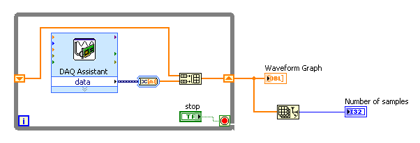
But the DAQ Assistant, putting your own code DAQmx (for something as simple as buying 1000 samples, DAQ Assistant is good!)
Make sure the Array function to build is set to concatenate entries, also convert Dynamic Data has the value table 1 d of scalars-automatic (but this is only important with the DAQ Assistant)
I hope this helps!
Tags: NI Software
Similar Questions
-
Hello:
I'm very new to LabView, so I need help to find an idea that can help me to record data continuously in real time. I don't want the file is too big, so I would like a new file in Crete in each 32 mega bytes and clear the previous buffer. Now I have this code can save data of voltage in the TDMS files and the sampling frequency is 2 m Hz, so the amount of data very fast increase and my computer have more ram 2 G, then the computer hangs after 10 seconds, I'm starting to collect data. I need some advice you briliant people.
Thank you very much I appreciate really.
I'm a big supporter of the architecture of producer/consumer . But this is the place that I recommend. The DAQmx Configure Logging does all that for you!
Note: You will want to use a table instead of a graph here.

-
acquisition display continuous data on 1 chart and display medium on another
Hello
I created the VI to display the last 100 values on a chart and on average every ten values on another graph. So when 100 values on the first graph, the values of the ten (where each is the average of 10) are displayed on another. The code I created for this purpose is attached.
I don't think I realized that I started to because:
The X axis is time in seconds and no number for each value, unless there is a value acquired every second.
If I pass the highlight performance, average Bulletin Board expect top 10 values are displayed on the waveform table. It should then display a single average value. He should do it for every 10 iterations. However, it is not the case.
Could someone if please change the code to me and advise on how to change x axis of time to any other variable where necessary.
Thank you in advance for helpHello
In code, you do mobile window. However, from what you describe, you want a fixed window without overlap. I changed the following code, see the attachment.
1. I change the x-axis of time at the point.
2. I put the 2nd table in a box structure. The 2nd table will update only when the loop iternation is divisible by 10. Let me know does this work for you.
Yik
-
Excerpts from continuous data acquisition
Hello
I want to make an acquisition of continuous data with a NEITHER-6133 @ 1ms per channel. The data must be stored on hard disk. At the same time, I want to take excerpts from acquisition to calculate different values. The acquisition of the extract must be triggert by an external digital trigger. Are there examples, which combine continuous data collection and collection excerpts?
Thank you very much.
Best regards
Michael
System
Windows 7
LabVIEW 2012
NOR-6133
Thanks to the support of NOR-Germany, I found a solution for me:
1.) continuous trigger switch
Connect 2) the trigger for the signal to a digital i/o
3.) synchronize AI and DIO
Excerpt 4.) the samples needed by the search within the digital waveform pattern
Result:
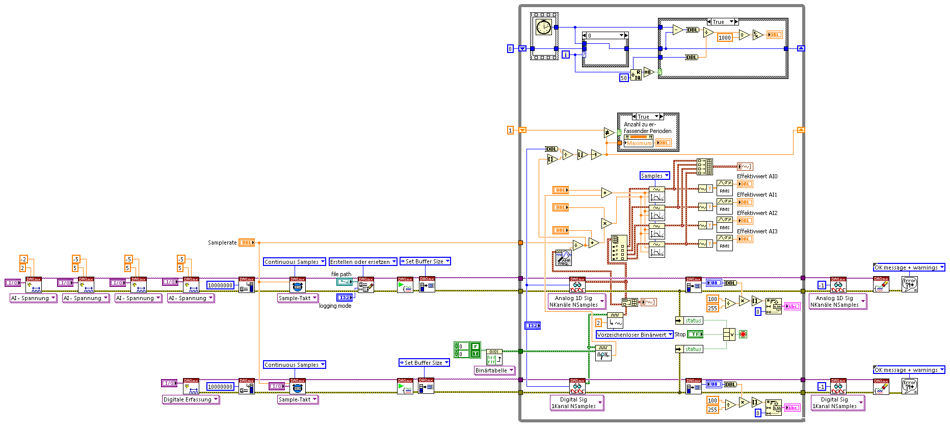
The example shows 4 IA channels Cup (tested on Win7, NI PCI-6115, 4 channels each 5. MECH / s) and calculation on extracts from each channel signal triggered parts.
-
How .vi DAQmx Read (analog 2D NChan DBL NSamp) to acquire continuous data?
I try to get the .vi DAQmx Read (analog 2D NChan DBL NSamp) to acquire data continuously. The 'help' indicates I need to wire the number of samples per channel-1, but it doesn't seem to work for my application. If I have the wiring to any number greater than 0, the data collection works, but is not continuous. I enclose the code (Sept15_MainPanel_WorkingBaselines_ApplyBaselines and Calibration.vi) and a Subvi (Collect_Baselines.vi) if someone wants to take a look.
Here's what I'm trying to do:
I use a unit NI USB-6009 to collect analog voltages of load cells 2 (channel 0 and channel 1) and 2 displacement transducers (channel 2 and 3). The main panel of the VI contains a listbox with 4 options - 'Check EMG channel', "Collect base lines," "Collect Data" and "end of program". 'Collect base lines' 'End of program' work and I'm working on writing code to "Collect data".
For the option "Basic collection", 2500 samples are read from 4 channels described above and 2500 samples are averaged. This works.
The option "Data collection" - I would like to that data from 4 channels to acquire permanently. Finally, for the option of data collection, data acquisition stops when channel 0 detects the force of 200 N - so I will not always have a finite number of samples read. The time it takes to reach the value of this force will be different for each test.
-How can I get continuous samples for my 4 channel? Is .vi DAQmx Read (analog 2D NChan DBL NSamp) function badly and if yes, what should I use?
Thanks in advance for any ideas or advice.
Esther
First, in case 1, you need not the structure of flat sequence. The son of the error and data properly will dictate the flow of execution. Then, in State 2, you must initialize the shift register, unless you want to keep the data is accumulated each time that you run the vi. The reason why you don't see all the data here is because you have - 1 wired for the number of samples per input channel. You must connect a number here, even if you are taking continuous samples. The service needs to know how much sample to gather at one time. If you put-1 here, the number of samples per channel must be set up in the synchronization function DAQmx (sample clock). If you specify a number here, then you put-1 in playback function. The DAQ hardware will read continuously, you must retrieve the data from time to time, so you must specify the number of samples. By reading inside a loop, it will continue to read until the stop function is encountered. I guess that the Clear function acts as a stop. But you must always indicate playback vi how many samples to read and return on each iteration of the loop.
The documentation is a little misleading. He warns that a - 1 will cause a continuous reading. But the pads are so big, he can not read continuously forever without losing data. If you specify a finite number, playback in a loop, and he will read this number and return the data (empty the internal buffer) at each iteration of the loop. Continuous means that you just call the start function once. He will read at each iteration of the loop until the stop function (or clear) is called.
Here is the difference between the setting of the Timing DAQmx function for continuous or finished reading: finite samples requires a tenure, he reads the finite number of samples, and it's done. It requires another start to read more data. Continues to read requires only a start. It still reads a finite number of samples, but when this is done, you can retrieve the data by calling the read function until he could continue. After the reading, you don't have to call for new start. Look at it this way. Start is what starts the collection of data, not the read function. Just read empty buffers in your data feed. The data acquisition continues in continuous mode, but you must call read again to get the data on the pads. If you specify basically buffer size when you set the number of samples per channel.
-
How to stop a single channel of data acquisition while continuing to monitor another?
I wonder if it is possible to stop and collect data (Ex: send Excel) from a channel on my acquisition of data (Ex: channel ai0), but continue to collect data from all channels (Ex: ai2).
You do so much too difficult for yourself here.
1. you use graphics. It's great! Here's the thing about the graphics: they keep a story. So there is no need to append waveforms Just wire the waveforms directly in the table.
2. change your Dynamic Data type for a waveform output. It will make your cards a little happier.
3. you can right click on the card when the program is running and that there is an option to export-> To Excel. No additional coding necessary.

-
Hello
I use a data acquisition unit integrated in a unit of 2 balls of hair, installed with a Zilla controller on an electric vehicle. Hairballs allows other devices to the device via a serial RS-232 port. The option of data acquisition for displays information like speed, tension etc.
I use Teraterm, a terminal Communicator to start communication with the device of hairballs. After having sailed in the various menus, I can access the DAQ feature that provides data continuously to the status of the various components of the vehicle. 5B 01 0b C8 03 53 02 39 27 OMFS is, for example, a sample of data from the module of data acquisition.
When the port is configured to send these data, I close the program Teraterm and run the vi in LabVIEW (series of reading and writing to .tdms only.vi) which stop automatically in 25 seconds (so recording 25 readings). It gives an error (-1073807252) saying that VISA: (Hex 0xBFFF006C) an overrun error occurred during the transfer. A character not read in the material before the arrival of the next character.
I'm unable to change the output of the device of data acquisition. In fact, the DAQ hardware has no controls what so ever. Thus, all the necessary adjustments must be made in LabVIEW.
Is there a solution to this problem? What could be the likely causes?
Thank you for your help in advance.
Best regards
Akhil Kumar mountain (M.)
Year 4 | Undergraduate | Mechanical engineering
National University of Singapore
E-mail: [email protected]
Mobile: (+ 65) 9326 7069
Hi Akhil,
I would be really grateful if you type my username properly - should not be so difficult to copy & paste the 5 letters

"So you are saying that if I increase the rate at which I accepted data, (for example every 500ms) the problem should disappear.
Yes. Read the more often you less likely buffer, you will get a buffer overrun...
"There when even to"Refresh"the buffer after each reading taken? ... How can you increase the buffer? »
Did you look at the advanced features in the VISA-> 'VISA'-> ' / unique Bus Interface "palette? It's all in your face
"Also a faster computer to run the program would help?
Certainly NO! These days, any computer is fast enough to handle standard RS232 serial communication...
-
Hello
I am currently working on the acquisition of data from a unit of 2 balls of hair, installed with a Zilla controller on an electric vehicle. Hairballs allows other devices to the device through a serial port. The option of data acquisition for displays information like speed, tension etc.
I use Teraterm, a terminal Communicator to start communication with the device of hairballs. After having sailed in the various menus, I can access the DAQ feature that provides data continuously to the status of the various components of the vehicle. I saved the logfile of teraterm (Teraterm - Results.txt). 5B 01 0b C8 03 53 02 39 27 OMFS is, for example, a sample of data from the module of data acquisition.
When the port is configured to send these data, I close the program Teraterm and run the LabVIEW VI (read and Write.vi series). It accepts 2-3 rows of data (error LabVIEW - 2.jpg In Motion) and then stops. I know there is a message of error involved, but I think that its storage in what concerns the information in the file (this is another problem, I need to resolve, the file is always empty).
Could someone help me with this problem please. Why the software ends the execution after only 2-3 loops. Sometimes he starts to accept data from the middle (@ 1 0b C8 03 53 02 39 27 OMFS for example) and stops after displaying the it.
If there is information required please let me know.
Thanks in advance.
The error you get is:
1073807252 VI_ERROR_ASRL_OVERRUN A time-out error occurred during the transfer. A character not read in the material before the arrival of the next character. Your buffer is probably full of data.
-
Synchronization of data from different sample of data acquisition rate
I use a high RT 8135. I'm sampling of signals from analog pressure thermocouples to 20 ms and 10 ms. I use the stream network to transfer the data from the SMU on my host. I would like to be able to synchronize the timestamps of all data to the 1ms sampling note and record in a file.
Search in the file my sampling data 10ms end timestamp does not match the timestamp of 20ms, missing data... I know you have empty queues to get the rest data but is possible to interpolate any data to adapt a unique timestamp?
Thank you!
Hi aokada09,
Looks like you are facing problems resulting from parallel execution two loops you have. There is nothing necessarily bind the two loops together, so that each of them an iteration at the rates you specified, but are allowed to start each software (sort of random) dictates that they start.
To get a solid synchronization, share a sample between the two measures clock, but run the sample clock at 100 Hz for 50 Hz for thermocouple measurement and pressure measurement. You should be able to use shared inside the SMU chassis backplane clock. This will be as close as possible to synchronize without using a card of timing. The only real source of delay/tilt between readings at this point is the physical distance that must travel the clock signal. This will not lead to steep, but there will certainly be some (probably on the scale of the high-nanoseconds or microseconds bass). This article gives more information about the synchronization and the sample clock:
-
How to write data from the acquisition of data in NetCDF format?
I connect to a set of data from the sensor through the DAQ assistant and want to write all data in NetCDF format. I have the required plugins installed, but still can not find how to do this.
Or the labview can only read the netcdf files, but cannot write it! Please let me know if there is any other way out. I have looked everywhere but could not find something useful!
Thank you
Hey,.
Sorry, the sheet in effect only allows to read NetCDF files, not writing to the NetCDF format.
Kind regards
-Natalia
-
I32 flipping index iteration continuous data acquisition
I'm doing some continuous data streaming with Labview FPGA and periodically generate a trigger signal
the timestamp after a number fixed iterations.
The strategy I would try was to review the iteration index in the timed loop and whenever he tipped a fixed number I would generate a trigger of the FPGA.
I tried to find out what happens when you get to 0x7FFFFFFF samples on the register of I32 and apparently
the index does not roll... It just remains to count max once reached it.
Is there a way to derail the index on a timed loop? Otherwise I wil just add another
U32 variable and increment it each cycle and let it roll on.
the iteration count does not roll. Therefore at this historic moment, but just use a registry node, local or feedback shift instead.
-
acquisition of continuous sample with multiple channels
Hello! Please tell me what I'm doing wrong here, I'm confused about how the acquisition of continuous sample with several channels (using NI USB-6215 boxes).
Following code is python code, but I don't know who confuse you
 (and it's only a part of my code in order to not try, it won't work
buffer_size = 2000 #samples to read
sampling_rate_hz = 20000
channels = "Dev1/ai0 ai1/Dev1" #this can be a string or a large number...CHK (nidaq. DAQmxCreateTask ("", ctypes.byref (taskHandle)))
CHK (nidaq. DAQmxCreateAIVoltageChan (taskHandle, channels,"", DAQmx_Val_Cfg_Default, float64(-10.0), float64 (10.0), DAQmx_Val_Volts, None "))
CHK (nidaq. DAQmxCfgSampClkTiming (taskHandle,"", float64 (sampling_rate_hz), DAQmx_Val_Rising, DAQmx_Val_ContSamps, uInt64 (buffer_size) "))
CHK (nidaq. DAQmxRegisterEveryNSamplesEvent (taskHandle, DAQmx_Val_Acquired_Into_Buffer, uInt32 (1000), uInt32 (0), EveryNCallback_func, None))
CHK (nidaq. DAQmxRegisterDoneEvent (taskHandle, uInt32 (0), DoneCallback_func, None))
the callback function #and
def py_EveryNCallback_func (self, taskHandle, event_type, nSamples):
data = numpy.zeros ((self.channel_amount,buffer_size,), dtype = numpy.float64)
read = int32()
CHK (nidaq. DAQmxReadAnalogF64 (taskHandle, buffer_size, float64 (10.0), DAQmx_Val_GroupByScanNumber, data.ctypes.data, buffer_size * number_of_channels, ctypes.byref (read), None))With only one channel, everything's fine, and tension diagram looks like this:

buffer_size = 2000, sampling_rate_hz = 20000
But if I use two channels, voltage diagram looks like this

buffer_size = 2000, sampling_rate_hz = 20000
It looks like the sampling rate is higher or there are fewer values?, but with two channels with the results table is 2000 * 2 long and with a single result is 2000 * 1 long is not smaller
most of the settings important (?) in my code:
DAQmxCfgSampClkTiming "float64 rate": 20000 (sampling_rate_hz)
'UInt64 sampsPerChanToAcquire' DAQmxCfgSampClkTiming: 2000 (buffer_size)
DAQmxRegisterEveryNSamplesEvent "uInt32 nSamples": 1000 (?)
'Int32 numSampsPerChan' DAQmxReadAnalogF64: 2000 (buffer_size)
DAQmxReadAnalogF64 "float64 [] readArray": [[buffer_size] * number_of_channels]
'UInt32 arraySizeInSamps' DAQmxReadAnalogF64: buffer_size * number_of_channelsas you can see nSamples is a big question mark, but the problem still exists if I set variable buffer_size y (2000)
Hi Dazzler,
It is not a multi-channel example that ships with the driver, but after a quick look at the code that you use in your third post, everything seems to be configured correctly. The only thing I was thing I got a question about your plots. Looks like you draw each time the same number of points. If you draw just the table of data directly from the playback feature, you need to draw (buffer_size * number_of_channels) number of channels since the data returned is as an interlaced array. You can also choose to deinterleave samples. More information about this lie in the NOR-DAQmx C reference help, which is installed with the NOR-DAQmx driver.
Kind regards
Kent
Technical sales engineer
-
I am trying to take data continuously from 4 channels maximum 5Msamples per second and writes at the same time as the data on the drive using the TDMS writer. I use daqmx LabVIEW tools to read and write data. I get failry good flow, but it is not completely continuous.
1 is it possible in Labview?
2. is it possible with NIScope? NIScope is at all related to labview?
Thank you
Ben.
I'm not an expert DAQmx, but it is a fairly common use case covered by the API. You can configure DAQmx so that when the data are collected, it is written as efficiently on the disk. You can do it for a continuous data stream. You can find an example of this here (and more examples using the LabVIEW example Locator: Help-> find examples...):
\examples\DAQmx\Analog Input\Voltage - Input.vi continues This VI uses the data at the level, so you will want to choose not adjusted I16 data for the type of output to the maximum speed.
Alternatively, you can use a producer/consumer architecture, acquire data in a loop and it continuously to the PDM in another. It is essentially this as the example above, but much easier and more quickly, because it involves fewer copies of data.
Good luck!
-
How can I use notifications to send data from different sources for the same chart?
Hello
I use the model of 'Continuous measurement and logging' project comes with LV 2013.
It is extremenly helpful in understanding the messaging between the acquisition, graphic and loops of newspaper. (Thank you NEITHER!)
I ran into a snag though.
I want to change so that my graphic loop receives notifications of data from two sources of acquisition by the declarant.
I have trouble getting the data from the two sources to display on one graph.
I've isolated the problem in the attached vi.
Here's what happens:
1. I create 2 parallel loops data and send the data to a third parallel loop with the notifiers.
2. the third loop receives data from one of the loops because one of the authors of just receiving notifications is to expire instead of receive data.
Can anyone suggest how can I fix?
Thank you.
-Matt
Here's my modification of your VI. I put notes on the block diagram to explain the changes. He uses a queue for data transfer to avoid data loss. It uses a notifier to stop loops. All local variables and value property nodes have been eliminated.
The way loops are arrested probably let some data in the queue. No more of one or two iterations of each of the loops of data acquisition. If you need ensure that all data has been displayed (or recorded in a real application), then you must stop acquiring loop first and read the queue until you know it's empty and both other loops stopped. Then stop the render loop and release the queue and the notifier.
Lynn
-
Strange behavior when using Labview to collect data from Tektronix oscilloscope tds8200
I hit a wall in trying to understand this one. The problem I have is that my application will not start the oscilloscope when it should.
I use an oscilloscope Tektronix TDS8200. My goal is to collect data from the oscilloscope using Labview waveform. First of all, my program initializes and configures the oscilloscope; This part of the program works very well.
The second part of the program begins the acquisition of data with the function 'Tktds8k Start or Stop Aquisitions.vi', which is to press the button run on the scope. The function "tktds8k to Waveform.vi" is used and should ideally return data, which I connected to a waveform playback graph.
When I run my program, the first part runs without a problem, but as soon as the program comes to the service get the waveform, the run button in the scope, which is green when running, turns off; the program then expires, and no data is collected.
Here is where it gets weird. I went through the debugging to try to understand this point, and I put breakpoints on the beginning and get shape wave functions so that I could scroll through the last part of the program. The program continues with the departure function, and the button run in scope is green. The breakpoint for the function get the waveform is reached and when I press on continue, turns the Run button and turns it off then back on almost immediately. data are collected, the waveform graph appears and the program ends without error.
I thought that the timetable could be the problem, so I did the program wait as long as five seconds between the functions of start and get the waveform and that did not work. I also tried to move the start function to before the configuration functions and remove start completely; no method worked.
is there any ideas on why, the program works when I enabled breakpoints and isn't when breakpoints are disabled? I'm sure there is an easy solution, but I was not able to find a solution.
I have attached a pdf that contains information about the functions of the Oscilloscope (tktds8k.pdf), and I have also attached my program.
Maybe you are looking for
-
The "MyNewServerHostname" server did not accept the certificate.
Hello I have a server on a Mac mini with OS X 10.11 and a MacBook pro with OS X 10.11 customer who worked very well in the lab. But to put the server on another network necessary to change the name and the IP with the changeip command-line. Now the c
-
Element of cluster R/W by the property node
I have a table via nodes of property by using the value property, but have not found a way to do the same thing with a cluster. Am I missing something? Thank you Glauber
-
With brother printer troubleshooting
Printer says maintenance troubleshooting and systematics, how could I solve this problem? Thank you
-
Windows Vista tries to update or reinstall Adobe PDF help please!
I have problems updating or gel and reinstall adobe pdf I have window vista it keep giving me a busy internet message or % APPAP?
-
Desperately need help from blackBerry Smartphones - I can't read my messages PIN.
I have a Storm 9500 and does not know how to read my PIN messages. I work away from home and so my manual, and for all the google/BlackBerry forum research I did, no one explains how read , only send them. My companion with a new curve took my PIN an