Acquisition of data mx error must add on
I have a pc that has been refreshed. They have installed LabView 7.1, 8.0, 8.2 and 8.2.1 back on the new pc. After updating the drivers for a new USB-6525 assistant DAQ and the DAQ mx are gone and any VI that I used before that had them no longer work. I get a message which is requires an add-on. If anyone has had this problem or knows what I need to do to fix? When I try to load an example what either using the mx I get the attached warning picture.
If your code uses DAQmx and you do not have a reinstall, then you must install DAQmx. You can get the device drivers CD or you can download it from the site of NOR. Don't forget to look at the compatibility page to ensure that you get the correct version based on multiple versions of LabVIEW you have.
Tags: NI Software
Similar Questions
-
the scale of data acquisition and data entry error
I have a USB 6211 camera set to MAX for 11 different channels: the first 10 channels are configured with a scale factor of 2 while the last channel is configured with a scale of 1. I connected battery 9 V for the first two channels, ai0 & ai1, (level 2) and the last channel, AL10, (1 scale). The input pins were 15, 17 and 20 for input voltage with pin 28 connected as a reason. Then, I checked the feature in MAX. Surprise! I expected to see 18 volts for the first two channels and 9 volts for the last channel, but much to my surprise I got all channels showing data about 10.86 volts and the last channel showing a value of 7.79 volts! How is it that I see the values for channels not connected! In addition, why are values of cable channels so screwed up! With a 9 V battery and a scale of 2, I expect to see 18 volts, not of 10.86, and where the 7.79 volts for the channel which has a scale of 1! If I run MAX continuous mode instead of the sample N mode I get a few other strange results: I get a single horizontal line and 1 sinewave! It's amazing because I have a 9 volt battery connected to the unit! I don't even how arrays of the VI that uses these signals is like since they are all screwed. Will you please advise me on this one because I'm completely stumped.
-
Creating installation and acquisition of data-MX: Error Code
Hello
I found this question been asked several times in 2009 and 2007, but the answesr on the forum doesn't really help me - partially because they say: oh he just worked.
I'm trying to craete my first Installer for a LabView project.
It is simply an assistant DAQ for a card OR. I'm moving my a comptuer with LabView application than with the card = without labview and I prefer not to install labview on both.
When I include DAQ - MX and the Run Time module I get this error code for the installer.
Visit ni.com/ask support request page to learn more about the resolution of this problem. Use the following as a reference:
CDK_Build_Invoke.VI.ProxyCaller > CDK_Build_Invoke.vi > CDK_Engine_Main.vi > IB_MSI.lvclass:Build.vi > IB_MSI.lvclass:Engine_AddProductsToDistribution.vi > NI_MDF.lvlib:MDFDistBuildList_Close.vi
Loading information of product deployment
Loading information of product deployment**************
Error: Bad line of command or argument of function call. (Error code - 30)
Type 'DefaultFull' product ' KB5Q5FJ4QW NOR security for the LabVIEW Run - Time Engine 8.2 update ' is not found in the source distribution. " Insert the correct source distribution, or select a different type of product.
**************
Error details:
Error to the MDF API function: _MDFDistBuildList_Close
Error in MDF: istributionBuildList::AddDependentProducts.
Final report of the error
**************Don't know what this means

For this one
Type 'DefaultFull' product ' KB5Q5FJ4QW NOR security for the LabVIEW Run - Time Engine 8.2 update ' is not found in the source distribution. " Insert the correct source distribution, or select a different type of product.
I think it means that's not find the CD of where to get this Setup Wizard? Isn't it? Well it's never me invites to a medium where to find this file... so I'm stumped.
We'd appreciate any help, I will answer the weekend too!
Thank you!
Also, I have
Thank you.
I have attached the single file in my project I am trying to install...
Laughing out loud.
-
merger acquisition of data to read input data 2 or several at once
Hi all
I'm using or usb-6009 more then 2 incoming signals.
the problem is that I can't read 2 signals at the same time. 1 my daq assistance will be apeared to be error.
so, how can I set the .vi (attached) so that he could read 1 more signal since the acquisition of data?
I also tried to separate daq support but error. I also try to merge the two signals with a different port (a1 and a0)
can anyone help?
Thnx for the reply
Frankly, I went through all the tutorials and looked for answers in the forum and the conclusions I have difficulties to understand the technical language... I have been looking for everywhere labview users and found someone who could guide me carefully... im have desperately need guidance... not to give up hope trying to find the answer, but a sort of feedback that is giving advice that you need to take the driver's seat... FYI... I take the driver's seat... that look like a real Nubian now needs help...
is there any order step by step so that I could add channels more 1 1 daq help?... I've done it before, but it occurs.
for example, I want to create channel 1 to read the value of the resistance and channel 2 for playback of tension... but what happened when I create more than 2 channels, it is be will configure this channel only 1 located in the block diagram... both channal will give only data for the value of the resistance.
Sorry for my broken English.
-
Use two assistants for the acquisition of data at the same time
Hello
I want to read multiple data channels of analog inputs on my DAQ hardware. However, when I try to create two separate data acquisition assistants for each entry, it gives an error saying "is reserved for the specified resource. The operation could not be performed as indicated "." Can't use two assistants for the acquisition of data at the same time?
I have to add different channels in the same assistant DAQ? I tried, but I couldn't separate the data in different graphs.
How does this work?
Kind regards
Allard
You can't have multiple tasks of the same type (in this case inputs analog) on the same device. Just so having 1 DAQ Assistant read all your channels and separate your channels for individual transformation.
-
get the 1726 error: cannot add the port monitor
get the 1726 error: cannot add the port monitor hp discovery port monitor (hp photosmart 5525 series) running Windows XP, HP Photosmart 5525
Could not complete the installation.
Hi Jeff,
The computer manufacturing must have created a partition on the disk or provided you CD to restore the computer to the way it was when you bought it. If you have a PC clone, then probably you need to reformat your hard drive and reinstall the operating system. If you have an OEM computer (example: HP, Dell, ETC) there is most likely instructions when you turn on/off press F11 or F12 to return the computer to the computer.
Note: Do nothing until you have all of your backup data.
-
Satellte M30: BSOD - KERNEL DATA INPAGE ERROR atapi.sys
Hello
I really hope, really, that someone can help me. I'm no computer Wizard, so if you can help please give me simple instructions. My problem is that often my satellite M30 freezes and blue page happens to give me a warning.
Top of the page is KERNEL-DATA-INPAGE-ERROR, then goes on to say disable Options memory BIOS such as cache or shading, atapi.sys says below.
So can someone please help.
Thank you
Hello
Because you are not a computer expert ;) I'll try to write as simply.
It looks more like a hardware problem as a problem of software!But to be 100% sure, you should recover the laptop with the Toshiba Recovery CD supplied.
This CD will be programmed the laptop back to the factory setting and usually the laptop should work properly after the recovery of the new!If you the BSOD will appear again the chances are high that memory, HARD drives and the motherboard is malfunctioning.
But because you are a beginner, I would not recommend trying to solve this problem yourself.
In this case, you must contact the ASP in your country!Good luck
-
Equium A300D - 13 X - Configration system data read error
Hello
I have a problem with my Equium A300D - 13 X laptop, everytime I turn on my laptop it starts and loads the initial startup screen as usual, Toshiba once asked that loud "BEEP" comes from my laptop, and lists the following information:
Phoenix TrustredCore (tm) NB
Copyright 1985-2006 Phoenix Technologies Ltd.
All rights reservedHerring of the ITA (DDR2 + T/RS690M/SB600)
CPU speed = 2000 MHz639K system spent RAM
1918M extended RAM passed
1024 KB of L2 Cache
Occult system BIOS
Video BIOS with a shadow
ATAPI CD-ROM: MAST * ADVD-RAM UJ-850 S
Fixed disk 0: WDC W2500BEVT-00SCSTO
Fixed disk 1: Hitachi HTS542520K9SA00
Initialized the mouse
ERROR
System Configuration data read errorPress
to resume, installation I replaced the hard drive and flashed the BIOS settings as advised by Toshiba Helpline but the problem persists.
Help, please! because the "BEEP" is now getting on my nerves!
See you soon
Hi andrew_net82,
It seems that the BIOS has detected an error with a certain part of material...
Before doing something I recommend you load the default settings in the BIOS. If you are in the BIOS Setup, press the F9 key.
If it doesn t work you need for professional assistance from an authorized service I think. Guys need to check which part of the material is defective and must be replaced.
List of the ASP, you can find on the official website of Toshiba. -
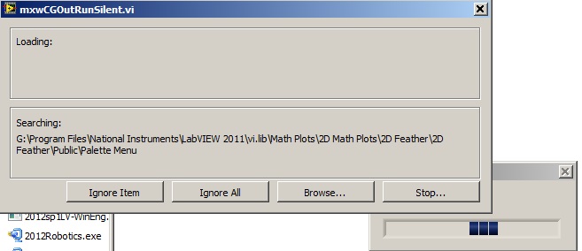
Acquisition of data NOR usb 6008: a strange problem: mxwcgoutrunsilent.VI is not respected
Expensive OR
Today, I bought an acquisition of data NOR usb 6008
and I'm using labview in 2011
the problem is appear when after I end the process of configuration of the i/o data acquisition Wizardthe following image shows the mxwcgoutrunsilent.VI is ignored and an error has occurred
someone can help provide this VI for me
What is the complete labview modules can also so I could do a real time data acquisition
Best regards
mangood,
You received an error code? If so, what is it? What version of NOR-DAQmx driver you have installed? It seems your driver potentially incorrectly installed, and you may need to reinstall the driver.
Here is the link to the latest version of the NOR-DAQmx driver: http://www.ni.com/download/ni-daqmx-9.8/4297/en/
-
We send 5v data acquisition using a voltage generator. Hook us it up to a voltmeter and see 5V. When connect us the generator voltage to a valve "normally open" parker, the voltmeter indicates .14V. It seems that when we connect the two sons of the valve for the voltage generator, the son act as pattern. We want to control the voltage flowing to tap through Labview. We checked the wires to the valve and they work very well, because if we send a constant 5V since the acquisition of data and put ashore, she, the voltmeter indicates 5V. Someone knows why the son act as pattern and low blood to .14V?
nsatpute wrote:
Our data acquisition is NI USB-6259. The valve requires only a 5V max and our DAQ provides up to 5V. However, after connecting the valve to the acquisition of data, the grave tension to almost 0. We start from the principle that the son somehow act as the reason, but we are not sure if this is the case.
The question here is not how much voltage the valve wants, it's the current needs of the valve. The 6259 can put only 5mA via an analog output. Your very likely tap needs much more than that. If you need to add in an amplifier circuit that can supply more current to operate your faucet.
-
Hello
I try to save a path in a table in an access database, but an error occurs:
"Exception occurred in the Microsoft Access database engine: the field is too small to accept the amount of data you attempted to add." Try insert or paste less data. "in create a NI_Database_API.lvlib:Rec - Command.vi-> NI_Database_API.lvlib:Cmd Execute.vi-> NI_Database_API.lvlib
Data.vi B tools insert-> project total.vi.I've attached a JPEG of a part of the code and the code, but it won't work because the database is not attached,
any help please?
Ok
I solve the resized problem.i column size
Thank you
-
Several acquisition module and the error
Let me start by saying: this is the first written time code to communicate with the DAQ hardware and I'm learning. I develop a test bed that will have different inputs and outputs listed below:
cDAQ 9172:
Mod1: NOR-9211 (4 Thermocouples)
Mod2: NOR-9211 (3 Thermocouples)
Mod3: Not currently used
Mod4:-OR-9201 (flow 6 sensors)
Mod5: NOR-9201 (5 pressure sensors)
Mod6: NOR-9481 (4 relays)
Mod7: NOR-9481 (3 relays)
Mod8: NOR-9401 (2 float switches)
Of after a suggestion of a more experienced colleague, I was going to have an another while loop for each type of module running in parallel from my main program. For loops, I do a "Create Channel" and then "Start Task" as a setting the clock before entering all loop. I started to do that with the switch float (DI) and the 1 loop for each fo relay cards (DO) and then 1 loop for the 7 thermocouples (HAVE). That all ran fine with values update as needed and I could control all relays. When I then added the next loop to read in pressure sensors, I get an error in 'Start the task' for loop making the entrance of thermocouple, saying that the resource is reserved. I don't know what is the cause, the task name is unique to each loop and that they acquire signals from different modules. My method works? Do I need to have just a single loop for all modules? I don't know how I would do a loop when I have so many different types of data. I can add screenshots later if needed, I'm not near this workstation currently and it is not connected to the internet.
Here is a knowledge base that gives a way how to do this
.. .but really, it's all is creating a 'task DAQmx' and then passing this task to several "Create Channel XX" live (tasks are composed of one or more channels). It is more readable if you call 'Create DAQmx Task.vi' and then use the task as an input for each of your 'XX.vi create channel' live it was you can even name your task 'Task My AI' and then it's easier to debug.
Just for the record, the knowledge base does not call to 'Create a task DAQmx' explicitly as the first 'Create channel XX.vi' will implicitly do it for him.
-
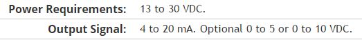
Here is my sensor
Pressure sensorHere's the DAQ data sheet:
Here are my issues:
First of all I don't know what is LO and HI exactly in the DAQ 9219 material.
Second, I don't know what pin code I should connect the DAQ sensor signal wire. PIN 4 or 5 pin? The sensor has three pins, and I guess I should connect the other two wires to the power supply.
Thirdly how to calibrate the sensor. In labview choose voltage in the wizard?I'm pretty new in this acquisition of data and I need your help.
Thank you
Hi SilasIII,
Hmm well 3 sons are probably on the ground, the power and the return signal. The datasheet for the sensor says:
First of all, you need to know which model you have (4-20mA, 0 - 5V or 0-10VDC). HI refers to the return signal, LO essentially means the land of the food that feeds the sensor. Then, you must get the 13-30 VDC supply. I don't think this should be too complicated and can be a simple wall DC power. You can learn how to create a custom in DAQmx scale. I hope that this is a starting point.
Kind regards
Eric
-
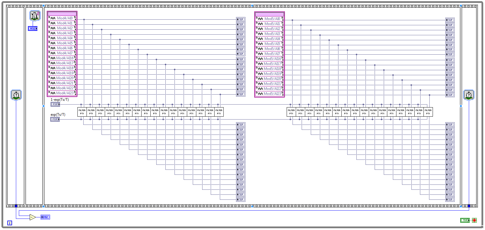
Acquisition of data and filtering on FPGA
Hi all
I have trouble to design a FPGA program for acquisition of data and filtering.
I have two NOR 9205 modules configured to work in terminal mode of DIFF, i.e. There are 32 entries this program must read every Ts seconds. (Ts is the time discretization, i.e. during the period of loop)
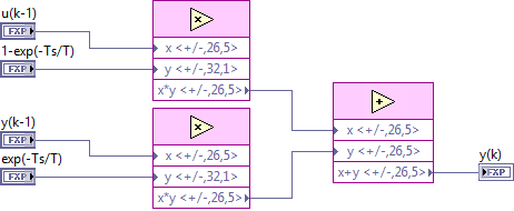
With respect to the digital filter, I implemented a possible simple filter with transfer function G (s) = 1 /(1+sT), which is part of the field of discrete-time equal to y (k) = a * u (k - 1) + b * y (k-1), where u is the original signal, and there is filtered signal. The coefficients a and b are equal to: a = 1-exp(-Ts/T), b = exp(-Ts/T), and T is the time constant of the filter (usually T > 5 * Ts).
The implementation of main program for the acquisition of data and filtering are:
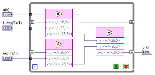
This application is for the digital filter:
However, the problem is that this program cannot take the FPGA resources on cRIO-9114, and Yes, I tried to define the criteria of compilation for the area. I also tried to implement the multipliers in digital filter as lut and DSP, unfortunately without a bit of luck.
Because I don't have that much experience in programming of FPGA, someone has any suggestions how to improve this code to adapt existing FPGA resources?
Best regards
Marko.
Hey Norbert_B,
I managed to solve the problem. First, I changed the reentrancy of Preallocated incoming execution clone to not reentrant execution. As no reentrant VIs have States, I had to use the node of the feedback to the main VI to get u(k-1) and y(k-1). Another important thing is to choose Ignore FPGA reset method in the node of the properties of FPGA implementationfeedback, since in this case, the feedback node uses less resources.
Here is the new main program VI:
And here's the 'filter' VI:
Thanks for the help!
Best regards
Marko.
-
Acquisition of data stops at data acquisition
Hello
See the attached VI. Data acquisition acquires data without problem for a few minutes, and then suddenly the event structure does nothing but the timeout. I'm deliberately ignore the 200279 error that is generated when two triggers are too close to each other, because I want to just ignore these triggers, but perhaps which also prevents tasks at a certain time? I also tried to start and stop the task again in the case of timeout events, but it does not help (it causes an error). Is there a way to prevent either the DAQ card (I use the box USB-6251) of the judgment of the data collection or a better way to ignore triggers that are too close together?
I hope that I am making some sense here :-)
Thank you
Jeremy
Jeremy,
Thanks for letting me know about the 99% CPU usage. It is definitely the cause of your accident and can be avoided by putting a funtion waiting with maybe 10 milliseconds in your timing loop. However, if you want to keep avoiding strict with no node blocking, you will need to restructure your VI to use the Express VI of time elapsed since the range of Timing. You will find examples of the use of this VI in detailed at the bottom help.
Hope this helps, have a great weekend!

Maybe you are looking for
-
Satellite Pro L870-18R - no boot after upgrade CPU
Hello Bought the "SATELLITE PRO L870-18R" alongside a "Intel Core i7-3740QM 2.70 GHz FCPGA988 L3 6 MB 4 Cores CPU 2.70 GHz" to upgrade the processor and get a beautiful machine. Boots of machine as expected with its stock i3, but white LED will blink
-
Satellite C855 - Bluetooth does not work
I have just set up my new laptop today, after four hours of tearing my hair with windows 8 I hate! I am not a techie and have had three Toshiba satellite before, but I hate windows 8, rant on about it.Main reason I chose this model was for Bluetooth.
-
Satellite A200: Question on Slovak Vista recovery drive
Can you tell me, if I have a Satellite A200, purchased in France, EN Vista installed, is possible to move to SK / Slovak / version of Vista. Thank you!
-
Satellite L850-B147 - WiFi disconnects
Satellite L850-B147 with Atheros WLAN Wifi disconnects automatically, even if the connection is available.It then automatically reconnects. Driver is up-to-date. Other devices on the same router work perfectly.
-
What kind of RAM setup aspires it e1-572 did he? 4 + 2 GB?
The standard amount of RAM in the E1-572-54206G1TMnkk is 6 GB, 8 GB is the maximum supported. I was wondering if it was 2 GB + 4 GB, or simply a 6 GB card. Thank you in advance!