Acquisition of data stops at data acquisition
Hello
See the attached VI. Data acquisition acquires data without problem for a few minutes, and then suddenly the event structure does nothing but the timeout. I'm deliberately ignore the 200279 error that is generated when two triggers are too close to each other, because I want to just ignore these triggers, but perhaps which also prevents tasks at a certain time? I also tried to start and stop the task again in the case of timeout events, but it does not help (it causes an error). Is there a way to prevent either the DAQ card (I use the box USB-6251) of the judgment of the data collection or a better way to ignore triggers that are too close together?
I hope that I am making some sense here :-)
Thank you
Jeremy
Jeremy,
Thanks for letting me know about the 99% CPU usage. It is definitely the cause of your accident and can be avoided by putting a funtion waiting with maybe 10 milliseconds in your timing loop. However, if you want to keep avoiding strict with no node blocking, you will need to restructure your VI to use the Express VI of time elapsed since the range of Timing. You will find examples of the use of this VI in detailed at the bottom help.
Hope this helps, have a great weekend!
Tags: NI Software
Similar Questions
-
data acquisition stops automatically
I want to stop assistant DAQ automatically after a period of time, so I created this VI.
When I start the program, it work and after reaching the value of time specific 50, the graphical indicator ' looks like "stop, but wait after 9999 second, the graphical indicator suddenly see a lot of data that seems to be taken for the 9999 seconds, what is happening? After that, it gives an error saying:
Possible reasons:
Attempted to read samples that are no longer available. The requested sample was already available, but has since been replaced.
Increase in the size of buffer, most frequently the reading of data or by specifying a fixed number of samples to read instead of reading all available samples would correct the problem.
Property: RelativeTo
Corresponding value: current playback Position
Property: Offset
Corresponding value: 0Task name: _unnamedTask<100>
Data acquisition cannot be stopped like that?

Thank you
Not quite. Like this.

-
How to stop a single channel of data acquisition while continuing to monitor another?
I wonder if it is possible to stop and collect data (Ex: send Excel) from a channel on my acquisition of data (Ex: channel ai0), but continue to collect data from all channels (Ex: ai2).
You do so much too difficult for yourself here.
1. you use graphics. It's great! Here's the thing about the graphics: they keep a story. So there is no need to append waveforms Just wire the waveforms directly in the table.
2. change your Dynamic Data type for a waveform output. It will make your cards a little happier.
3. you can right click on the card when the program is running and that there is an option to export-> To Excel. No additional coding necessary.

-
Hi all
I'm new to LabVIEW
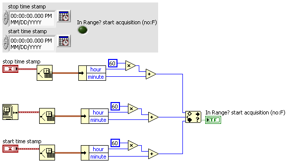
I want to create a program that can start acquiring data at 05:00 and stop at 19:00 and restart at 05:00 in the next day and so on
The ilustration is as below:
05:00 September 20, 2012 beginning of data acquisition
19:00 September 20, 2012, stop data acquisition
05:00 September 21, 2012 beginning of data acquisition
19:00 September 21, 2012 stop data acquisition
and so on...
Can someone help me on this please?
I have attached the VI below
Thanks in advance

OK, ok... im just a padawan! BTW, take care of your stress points...

-
digital triggering of stop/start of analog data acquisition
I want to use a signal from a digital line to start and stop analog data acquisition. The signal can change levels several times during a race of the VI so I have to start and stop several times data acquisition and store each session data in a different file.
I tried to play with the following screw: digital triggering of break, DigitalStartandStopTrigger and ContAcq_DigTrig. None of them doesn't seem to work for my configuration. I also do continuous data acquisition so I can't use a reference. I use PCI 6259 DAQ.
I used the "P0" pins rather than PFI pin on the grid BNC-2090. I know... stupid enough.
-
Problem to stop the task of continuous using API C DAQMx data acquisition
I'm doing the acquisition of data in the PCIe-6536 continuously using DAQMx C API. But whenever I try to erase the task and put end to my application, program stops and it is not completed by the Task Manager and task killer applications. Can someone help me with this?
Sameer
Hi John,.
Thank you for your concerns. the example attached also created the same problem. Then I run the test of the device to the MAX and it failed. Then I realized that there is something wrong with the installation. I simply uninstalled the card and installed on the other PCI-e slot. This time, self test has been successful and so did my request.
So my problem has been resolved

Again thank you for your quick response.
Sameer
-
Run two Executive files get signals of a data acquisition
I am a new user of LabView and I try to execute the two files on a computer that gets signals of an acquisition of data (that is, NI USB-6210). However, a single file is working correctly and display the values of signal while the other stops. I couldn't run two of them simultaneously. How can I solve this problem? Please do me advised.
You can not. You can not have two different tasks running on the same device at the same time. The second executable probably shows an error of-50103, assuming you have something in there to display errors.
-
Configuration of delay IO in 6587 of NI Data Acquisition
Hello
I'm reading LVDS data using adaptation module with module FPGA 7966R 6587. The external clock that I receive is identical to data (just hi-lo swing). In order to capture the data I need to move to the phase of the clock by a quarter clock cycle to get more stable data values. As the clock of TIME is not accessible (always set to 0) I think spend all my data accordingly. I have some questions on how to use DATA_IDELAY_INCREMENT to do this.
(a) high-level logical DATA_IDELAY_INCREMENT increases the delay of data by a single tap by ACQ_REGIONAL_CLOCK, where a single tap is 78.125ps nominal, so what do I do to get a period of 400ps? Is linked to the number of edges mounted on DATA_IDELAY_INCREMENT?
(b) how I use IDELAY_CALIBRATION_CLOCK?
mbothra,
To answer your first question, you must have a loop configuration that sets DATA_IDELAY_INCREMENT to true for a lot of clock ticks that you need to reach 400 ps. The DATA_IDELAY_INCREMENT node sets the entry activate the primitive IODELAY Xilinx to true, and the direction of the IODELAY is hardcoded to always increment. This means that for each beat clock where the node DATA_IDELAY_INCREMENT is true, the delay increases by 78,125 ps.
In your case, you would need to graduations to 400/78,125 or 5.12 (is rounded down to 5 graduations for 390,625 ps or delay up to 6 ticks for a delay of 468,75 ps). For this implementation, you might have a loop single cycle timed for the number of iterations, you need, stop the loop, and then start your curls for the acquisition of real data.
For your second question, the IDELAY_CALIBRATION_CLOCK is locked at 200 MHz. There is no change that you can do with this value to cause any kind of delay.
-
pulse width of measurement of signals generated by data acquisition
Finally, I would like to:
Start a counter pulse width measurement and the analog output at the same instant.
Stop the measurement with an external digital signal pulse width.My current plan is to use a digital output on the acquisition of data to synchronize a digital input and the start-up of the meter input. The digital input will be a trigger to start for the analog output. This works, except for the meter.
While trying to implement this, I tried a simple test to generate a digital pulse with the acquisition of data and wiring for counter inputs. It does not, even if it seems perfect to an oscilloscope. Then, without changing the software at all, I connect a function generator to my counter entries, and it measures pulse flawless widths.
I'm actually implemented it with a Python wrapper around the C DAQmx API, but I recreated in LabVIEW, and it has the same. VI attached. I have the latest drivers DAQmx.
Accidentally, I posted this in a forum for LabVIEW, as I managed to post with the account of a colleague. I think 2 ups live as this mandate to another post. I'm sorry. Former post is http://forums.ni.com/ni/board/message?board.id=170&message.id=389856.
Solution: I had to set the channel to counter with implicit synchronization. In addition, the sampsPerChanToAcquire must be at least 2, if not, there is an error. I still don't understand why it worked with a source of external impulse, however.
DAQmxCfgImplicitTiming (task_handle, DAQmx_Val_FiniteSamps, 2)
-
How to increase the speed of data acquisition?
Hey, currently I using 6210 OR of data acquisition and control switch. I used labview to periodically check the 7 switches and read data from 7 channels in the meantime (1 sample on request). I ran 70 loops for 10 groups of data, the cost of the time looked like 2.2 seconds.
I would like to end a 700 loops in 2 seconds, is it possible to improve?
Thank you
PEM
Look at the Terminal stop of the DAQ Assistant Express VI. You are starting and stopping of the task for the acquisition of data on each iteration of the loop.
Starting from the help file:
Stop
Specifies to stop the task and release device resources when this Express VI ends execution. For ongoing tasks, this entry is FALSE by default, which means that the task is running until the application terminates. To stop the task, you can use the device again in the same application, wire control wire you the Conditional stop this entry to the same terminal of the while loop. For single-point and finished tasks, this entry is TRUE by default, which means work stoppages after all samples are acquired. To optimize the performance of single point when using this Express VI into a loop, wire control wire you the Conditional stop this entry to the same terminal of the while loop.
Also from the help file:
Continuous single point of entry or exit, the of VI Express DAQ Assistant cannot allow optimal operation. See Acq & chart voltage-Single Point optimization VI in examples\DAQmx\Analog In\Measure Voltage.llb for an example of techniques to create more powerful applications, single point of I/O.
-
Digital acquisition of data streams
Hello
I tried (unsuccessfully) to acquire digital data of a sensor laboratory. The Guide from the manufacturer:
"When the excitement of voltage, DTC Decagon sensor makes a measurement. Three measurement values are passed for about 140 ms of excitement to the data logger as a character of flow series of ASCII. The series is 1200 asynchronous baud with 8 data bits, no parity and one stop bit. The voltage levels are 0-3, 6V and logical levels are (low active) TTL. The power must be removed and repeated his request for a new set of values to pass. The ASCII data stream contains three numbers separated by spaces. The first number is the depth of the water in mm, the second number is the temperature in degrees Celsius, with a resolution of 0.1 degree C, and the third number is the electrical conductivity in dS/m, with a resolution of 1 dS/m. A carriage return follows the three digits, then the character ' t "", which indicates that it is a sensor DTC, and then a control character, and finally a carriage return and supply line. ' "
My attached VI is a little dubious-it probably looks like something that someone used for analog signals may create. However, I was hoping it would be enough of a starting point for a more wise to work with LabVIEWer.
Thank you very much
Lacksagoo
The guide said in reality as a data acquisition card OR is the same as a data logger. I've never associated the two as being the same. What I think about a data logger is an autonomous instrument.
Looking for a more details in your original post, the voltage levels are not standard. You may need a shifter level or need to find a USB-RS232 adapter for TTL levels.
-
the relay control data acquisition
I am creating a vi that controls (press and release) several relay using a USB 6501 data acquisition. This should be a task relativily easy but I get flumoxed by errors. I tried to use the examples, but I get an error telling me that I need to use the mode of generation 1 sample (on request). Help, please
Sure. The easiest way is to have a DAQmx writing followed by a function of delay, followed by another entry, followed by another period. Simply plug the error links in order to control the flow of data. However, the VI would be insensitive so you can use a state machine or function elapsed time so that the VI can be stopped without waiting for waiting for him at the end.
-
I want to integrate the ANSI C sample program ReadDigPort - ExtClk.c in my own big package.
I want to use the internal clock of the BNC NI USB-6259 (.. 80 kHz 120 kHz).
In the document:
High speed M: Series Multifunction DAQ for USB - 16-bit, up to 1.25 MECH built-in BNC connectivity. / s,.
is written:
Or sample DI source clock: Any PFI, RTSI, HAVE sample or convert clock, AO, Ctr n out internal and many other signals sample clock
The digital subsystem doesn't have its own dedicated internal synchronization engine. Therefore, a sample clock must be provided another subsystem on the device or from an external source.How can I use internal clock case OR USB - 6259 BNC for the acquisition of digital data in my own big software?
With what other subsystem on the device can generate a source of the clock? How?It is possible to set a clock on an internal counter (for example ' Dev1/ctr0"):
Creates channels to generate digital impulses that define the freq and dutyCycle and adds the channel of the task that you specify with taskHandle.
DAQmxCreateCOPulseChanFreq (taskHandle, "Dev1/ctr0" units, clockName, idleState,
initialDelay, freq, the duty cycle); worksBut it is not possible to drive this internal clock to a terminal (for example "/ PFI0/Dev1"):
DAQmxErrChk (DAQmxCreateCOPulseChanFreq (taskHandle, "/ PFI0/Dev1", clockName, units, idleState, '))
initialDelay, freq, the duty cycle); does not work: error DAQmx: measurements: type I/O of the physical channel does not match the type of I/O required for the virtual channel you create. Name of the physical channel: PFI0. Name of the virtual channel: clockThe sample clock source can be derived from an external terminal (for example "/ PFI0/Dev1"):
Sets the source of the sample clock, the sample clock rate and the number of samples to acquire or generate.
DAQmxCfgSampClkTiming (taskHandle, "/ PFI0/Dev1", maximumExpectedSamplingRate, DAQmx_Val_Rising, ")
DAQmx_Val_ContSamps, bufferSize); works. Acquire or generate samples until you stop the taskBut it is not possible to derive the internal counter of the clock (for example ' Dev1/ctr0"):
DAQmxCfgSampClkTiming (taskHandle, "Dev1/ctr0", maximumExpectedSamplingRate, DAQmx_Val_Rising,
DAQmx_Val_ContSamps, bufferSize); does not work. Error: Acquire or generate samples until you stop the task: make sure that the name of the terminal is valid for the specified device. See Measurement & Automation explore valid names of terminals. Property: Property of DAQmx_SampClk_Src: DAQmx_SampClk_ActiveEdgeSource device: Terminal Source Dev1: Dev1/ctr0Hi datafriend,
using what it says is correct:
Or sample DI source clock: Any PFI, RTSI, HAVE sample or convert clock, AO, Ctr n out internal and many other signals sample clock
The digital subsystem doesn't have its own dedicated internal synchronization engine. Therefore, a sample clock must be provided another subsystem on the device or from an external source.This means that if you do not use an external signal as clock you can use the sample clock to HAVE it on board or at the output of the internal counter.
There are also 2 ANSI C examples in this regard:
http://zone.NI.com/DevZone/CDA/EPD/p/ID/4485
http://zone.NI.com/DevZone/CDA/EPD/p/ID/4488
So in both cases you have to use a fictitious task you need only for the generation of the internal clock (HAVE or CTR)
-
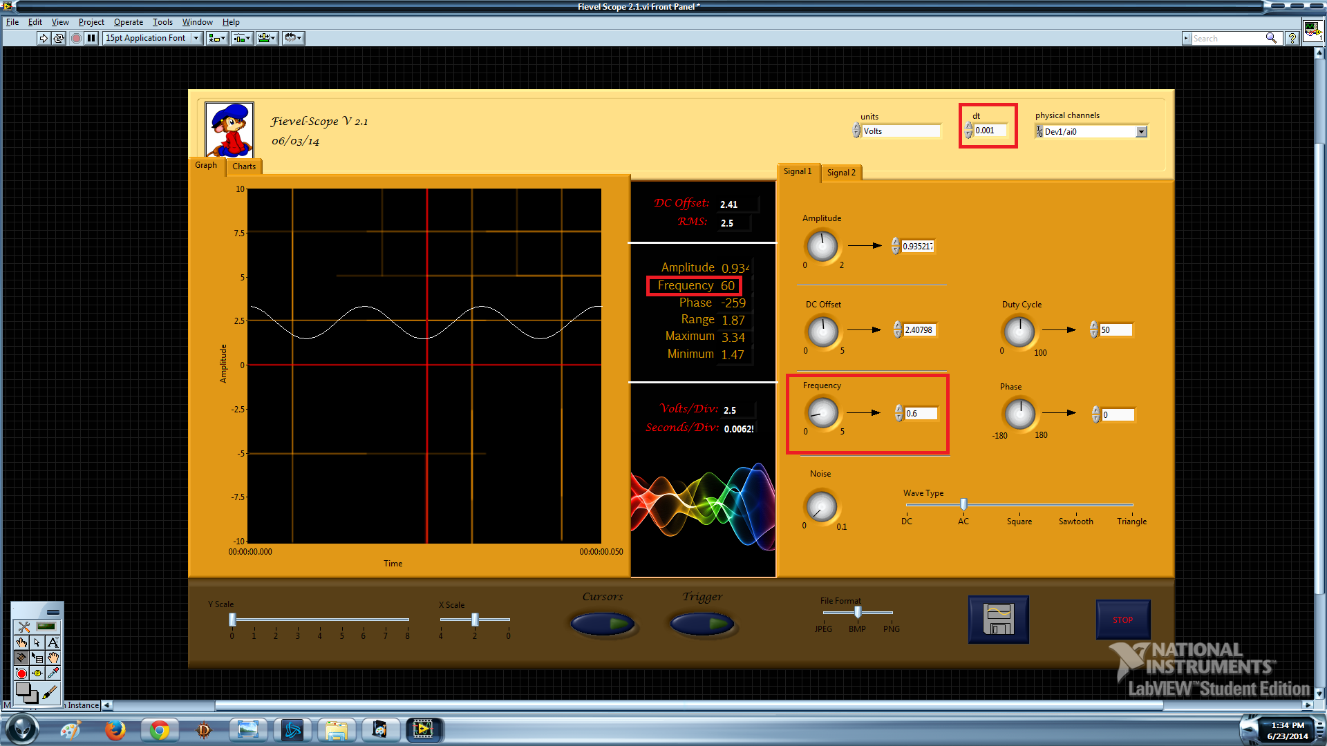
Virtual oscilloscope; Setting frequency of data acquisition
Hello world! I tried to program an oscilloscope using the Labview software and acquisition of data USB-6009. It will be very soon, but I can't seem to set the rate of acquisition of data at the correct speed. Let me show you what I mean:
waveform dt: 0.1
Frequency: precise
Limit: 5 Hz
Explanation: "[0.1 dt] is 10 Hz. Therefore Nyquist function, 5 Hz is the highest frequency that you can enjoy. Anything more than that will alias down in the 0-5 Hz range. "- Crossrulz
waveform dt: 0.001
Frequency: x 100
Limit: 500 Hz
Explanation:? The frequency seems to be dividing by dt at some point.
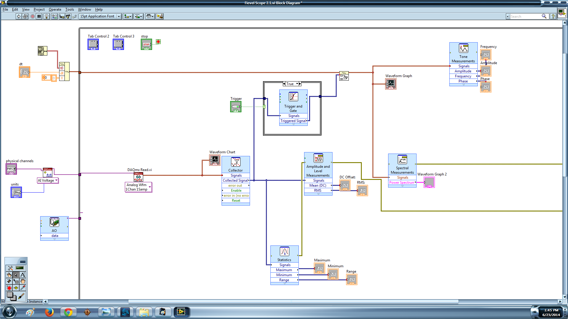
I like for this oscilloscope simultaneously read faster than 5 Hz and be precise. Here's my block diagram if someone would be willing to take a look:
Create the channel-> read-> buffer / collector-> Trigger-> Append--> measures/graphic
A last word: the dt that I am changing is on an empty wave form which I enclose with my signal to input in the upper left corner.
You run the examples that come with LabVIEW? STOP using the 1 sample DAQmx Read. Right-click on it, and change the type. The other mistake would come if you have changed the similar to the task. Delete this part because you don't use it.
-
2 channels of AI on a data acquisition with the range of different sensitivity
This vi is based on the 'new project' state machine on the home screen at the start of LV.
A time loop is parallel to the main loop of the state machine, shown in the picture.
It works continuously until you press the Exit button.
The problem seems to be in start this... > read >... stop start > read >... stop along the error line.
The reason for this clumsy arrangement power is measured voltages are in two lines of different sensitivity.
The shunt voltage is small and needs-. 2 to the range of V.2. The load voltage is greater and 09:50 V range is good.
In the initializing state, two separate vi 'create a channel' have been used to specify the range of voltage to the physical channel. The corresponding tasks are sent via via local variables.
DAQmx errors happen randomly, sometimes the first iteration, sometimes the 50th.
I tried to disable one or the other start > read > stop for the shunt voltage or load.
I tried replacing them with the DAQ assistant.
I tried various DAQmx vi: "wait" and "accomplishment of the tasks by resource cancel selected".
But error-50103 "specify resource is reserved" keeps popping up.
Is it possible to create two tasks on the device even when they are not used at the same time?
The only reason is to measure in two voltage ranges.
Win 7 Pro 64-bit
2014 LV database
Data acquisition equipment: USB-6210
Thank you.
This has been discussed many times. Do NOT use separate tasks. You can use different ranges for different channels with a single task. Just wire the task from one channel to another channel to create task.
You also use local variables when they are certainly not needed.

Maybe you are looking for
-
Is there a way to make the safari opens a new page every time?
Hello I'm kinda new here and I would like to ask a question. I now use an iPhone as a primary device, instead of Android. But is there a way to make the safari to remove all tabs when you close, and when you open it, it just opened a new page or a bl
-
Adding control to select the input of the chart data?
I have a device which sends several channels of data via TCP. I created a (attached) VI that analyzes this data in integer multiples. Can I connect a graph (I use graphics mode band) to one of these inputs. The problem is there is about 50 channel
-
Pass a CVI struct containing a type listed in TestStand?
Hello I have a CVI struct that contains an enumerated type. I want to call a CVI function with this structure as an argument of TestStand. I created a similar structure (type of container) in TestStand and the other fields of the struct appear to b
-
disable by program "resize objects.
I have a program that fits very well with some screen resolutions, I the "scale all the objects on the façade" selected. Is there a way to disable this option programmatically? I would like the user to be able to make the window smaller if you wish,
-
module SBUpdate on vista home no longer works
I run Vista Home on my PC. Every now and then the message arrives that the SBUPDATE has STOPPED WORKING. You are given two choices of MICROSOFT either by closing the module or that Microsoft will look for a solution. You can use one of the two choice