Acquisition of data usb6008 data measurment
Hi all
Actually, I'm a great fan of using labview.
Currently, the Im using USB-6008 for analyzing vibration of blade of wind with 4 accelerometers.
However, I can't collect output voltage 4 channels with my disguise of labview.
If possible, you want to let me know how to change my modeling of labview to collect 4 outputs at the same time?
Thank you
Hey,.
You need a table 1 d of waveforms.
Try the attached VI.
Tags: NI Software
Similar Questions
-
Operating system: Windows XP
Hardware: PCI 6259
Terminals used: PFI0 and PFI2
Counters used: Ctr0 and Ctr1
IM developing an application for the acquisition of data where timed loop synchronization source comes from my PFI2 (using the string A of an encoder). IM basically trying to acquire data based on the number of ticks from my encoder. For the synchronization source, I use counter 1 to capture the rising edge and have the loop time-acquisition of data. At the same time, Im using the counter 0 to count the number of rising edges so I know exactly in what tick data was acquired. PFI0 and PFI2 are connect to channel A of the encoder.
Questions:
Timed loop acquires data at each tick, because when I discover the data (text) file is missing count of my encoder value. Is it because there is a limitation on the Windows operating system? I used a noculars to measure the frequency at the maximum rotation of the channel encoder and 6,757 kHz. All solutions?
Also, is there anyway I can route the source channel internally an encoder to generate synchronization source instead of using another counter? I have attached my VI.
Hello
All the samples that you acquire will be read by LabVIEW in a sequential manner. Figure 4-21 on the M-series on page 80 (4-34) shows that you will acquire all the samples you request all channels that you enjoy in sequentially.
-
Acquisition of data reading zero intermittently
I use 3 analog inputs of an acquisition of data USB-6009 to monitor and record the temperatures of my system. This running VI constantly perform 1 read per second and periodically saving the values drop. Everything works very well for a few weeks or even months, until that data acquisition shows suddenly have a value of zero. unpluging the acquisition of data and by him plugging back in solves the problem. Therefore, I assume that this is due to the DAQ or maybe the USB communication being refreshed power cycle that I get the correct values again. Any ideas on how to test for the cause of this problem or preventive measures, can I take?
I was the closing of thought and could help restore communication at the end of each day.
Oh, and I'm using LabVIEW 2010 on Windows 7.
Disable the 'power save feature' Windows 7 where it randomly disables your USB hub. Go to Device Manager and go to USB hubs then the power settings.
-
Acquisition of data using C++ and cRIO-9066
Hello!
I want to write a C++ application that would make the acquisition of data from modules installed in the cRIO-9066 chassis and this application should work without LabView. How can I do? This chassis connect to my PC using NI-DAQmx? Is this possible?
Hi aanodin,
When you use a device that uses our architecture of RIO, it is usually best to use LabVIEW to develop your application. In this way, you can also program the FPGA with LabVIEW FPGA module and makes programming much easier real-time processor. In fact, your model of cRIO is officially supported by our LabVIEW programming language, as seen on page 4 of the Manual: (http://www.ni.com/pdf/manuals/376186a.pdf).
Due to the FPGA interface, you cannot use DAQmx with cRIO. I hope this helps.
-
Need a new acquisition of data USB multifunction device
Hello
Currently I use a PCIe - 6321 Multifunction DAQ hardware to control my stepper motor. I need to change the PCIe - 6321 and use the engine with a device for the acquisition of data USB multifunction bit PCIe - 6321. I'm not sure which USB model to select. Can I please get help about the choice of the right MIO USB data acquisition device that works similar to the PCIe - 6321.
Thank you
Bharath J S
The 6212 differs from the 6321 somewhat on the digital side, which probably you use to control your stepper motor. For example, it was only software DIO timed tasks and has only 2 counters with a set of features (e.g. no output meter in the buffer).
Best regards
-
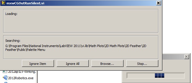
Acquisition of data NOR usb 6008: a strange problem: mxwcgoutrunsilent.VI is not respected
Expensive OR
Today, I bought an acquisition of data NOR usb 6008
and I'm using labview in 2011
the problem is appear when after I end the process of configuration of the i/o data acquisition Wizardthe following image shows the mxwcgoutrunsilent.VI is ignored and an error has occurred
someone can help provide this VI for me
What is the complete labview modules can also so I could do a real time data acquisition
Best regards
mangood,
You received an error code? If so, what is it? What version of NOR-DAQmx driver you have installed? It seems your driver potentially incorrectly installed, and you may need to reinstall the driver.
Here is the link to the latest version of the NOR-DAQmx driver: http://www.ni.com/download/ni-daqmx-9.8/4297/en/
-
We send 5v data acquisition using a voltage generator. Hook us it up to a voltmeter and see 5V. When connect us the generator voltage to a valve "normally open" parker, the voltmeter indicates .14V. It seems that when we connect the two sons of the valve for the voltage generator, the son act as pattern. We want to control the voltage flowing to tap through Labview. We checked the wires to the valve and they work very well, because if we send a constant 5V since the acquisition of data and put ashore, she, the voltmeter indicates 5V. Someone knows why the son act as pattern and low blood to .14V?
nsatpute wrote:
Our data acquisition is NI USB-6259. The valve requires only a 5V max and our DAQ provides up to 5V. However, after connecting the valve to the acquisition of data, the grave tension to almost 0. We start from the principle that the son somehow act as the reason, but we are not sure if this is the case.
The question here is not how much voltage the valve wants, it's the current needs of the valve. The 6259 can put only 5mA via an analog output. Your very likely tap needs much more than that. If you need to add in an amplifier circuit that can supply more current to operate your faucet.
-
Looking for a way to mount an acquisition of data USB-6008
Anyone has a suggestion for an acquisition of data USB-6008 mounted on a Panel. I use it for a system where it should not be loose. I have a few ideas, but hope that someone smarter already has a good solution.
Thank you
It is not a robust application, but the box will be moved and I don't want it put in the open air. I simply put a velcro pad on the back and the atttaching in this way. Should be all I need.
-
merger acquisition of data to read input data 2 or several at once
Hi all
I'm using or usb-6009 more then 2 incoming signals.
the problem is that I can't read 2 signals at the same time. 1 my daq assistance will be apeared to be error.
so, how can I set the .vi (attached) so that he could read 1 more signal since the acquisition of data?
I also tried to separate daq support but error. I also try to merge the two signals with a different port (a1 and a0)
can anyone help?
Thnx for the reply
Frankly, I went through all the tutorials and looked for answers in the forum and the conclusions I have difficulties to understand the technical language... I have been looking for everywhere labview users and found someone who could guide me carefully... im have desperately need guidance... not to give up hope trying to find the answer, but a sort of feedback that is giving advice that you need to take the driver's seat... FYI... I take the driver's seat... that look like a real Nubian now needs help...
is there any order step by step so that I could add channels more 1 1 daq help?... I've done it before, but it occurs.
for example, I want to create channel 1 to read the value of the resistance and channel 2 for playback of tension... but what happened when I create more than 2 channels, it is be will configure this channel only 1 located in the block diagram... both channal will give only data for the value of the resistance.
Sorry for my broken English.
-
Difficulty to read the instrument of series and acquisition of data simultaneously.
Greetings,
I have some trouble getting my VI read from my data acquisition and instrument of the series at the same time. If I run the Subvi simultaneously (i.e. subANG runs in a window and subVEL is running in a second window) both return the correct values and behave as I expect. However, if I call the Subvi in a society mother VI and try to run them both in the same loop structure subANG gets stuck and won't be reprobed with a signal change.
I also tried to use a stacked sequence or plate to separate the execution of subVEL and subANG, but I still get no response to subANG.
The point is is that, if I run Parent.VI in a single window and then creates a copy of subANG (call it '--copy' or other) and run it in a second window, Parent.VI behaves properly and will update the readings as they appear in '--copy '.
I enclose 3 files.
(1) subANG.VI - this bed an an inclinometer RS232 signal. The signal is refreshed every 10ms or more.
(2) subVEL.VI - this bed raw tension of a channel on the acquisition of data, calculates the average then that converts into a pressure difference and finally a speed based on the pressure and temperature inputs.
(3) ParentVI.VI - they simply call and displays the Subvi
My guess is that it's a buffer problem, but I am confused. Someone out there in Labview Earth knows why this might be happening? Suggestions welcom.
It is not an instrument of series. It is a UEI PowerDAq with their typical A/D and the cable.
I found away to make it work by placing subANG and subVEL in some time different loops side by side in ParentVI.
-
I have a PCI 6519 data acquisition card. I want to install it on the PC and use it outputs to control a robot. I have problems with the connections to the terminal block which is attached to the cable.
What type of connections I do for the acquisition of data PCI 619 card pins? What I have to give it to the ground and the CCV on the pins of the connector myself? What should be the value of the SCR I need to give to the PIN?
-
Acquisition of data using the DAQ card
Hello everyone
I need assistance with the acquisition of data of the generator of signals through DAQ cards. I plugged the signal to the SCB-68 generator where the analog inputs of the generator are connected to AI CH5 and AIGRND of the Terminal Board. Then the output of the block is connected to the DAQ card. The maximum sampling frequency of the card is of 250 kech. / s. The problem is for reason that I am not able to see the waveform on the labview. I looked at other examples to find the problem, I am, but I am not able to understand this. I want to be able to choose the sampling frequency. I attatched my code as an attatchment for you all to help me know what the problem is. Any suggestions will be appreciated.
There is no task! You have not specified any hardware (i.e. your data acquisition card) anywhere.
Here's a suggestion. MAX aperture. Find your DAQ hardware. Open a Test Panel. Implement a continuous sample of N Points to some sampling rate. Press Run and convince yourself that you get the data.
Now, while remaining in MAX, to create a task, using the same settings. Call for example something sensible ("MyFirstDAQTask" is not a good reputation).
Now, go back to your code. Eliminate the first two functions DAQmx. Wire a constant task to the DAQmx Start feature. See the little triangle down? Click it, and it should show you the tasks he 'sees', the only one should be the task that you created in MAX.
Note that 'Samples Visible' is now 'hard coded' in the task. To get its value back out, you need to put a property node Timing DAQmx after the task start and pull on the quantity of the sample, samples per channel (which, for reasons that escape me, is a Dbl, you need to convert to an I32 before importing it into the while loop).
Bob Schor
P.S. Thank you to join your code.
-
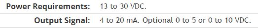
Here is my sensor
Pressure sensorHere's the DAQ data sheet:
Here are my issues:
First of all I don't know what is LO and HI exactly in the DAQ 9219 material.
Second, I don't know what pin code I should connect the DAQ sensor signal wire. PIN 4 or 5 pin? The sensor has three pins, and I guess I should connect the other two wires to the power supply.
Thirdly how to calibrate the sensor. In labview choose voltage in the wizard?I'm pretty new in this acquisition of data and I need your help.
Thank you
Hi SilasIII,
Hmm well 3 sons are probably on the ground, the power and the return signal. The datasheet for the sensor says:
First of all, you need to know which model you have (4-20mA, 0 - 5V or 0-10VDC). HI refers to the return signal, LO essentially means the land of the food that feeds the sensor. Then, you must get the 13-30 VDC supply. I don't think this should be too complicated and can be a simple wall DC power. You can learn how to create a custom in DAQmx scale. I hope that this is a starting point.
Kind regards
Eric
-
Restarting a task for the acquisition of data inside a For loop
Hello
I need iterate through my acquisition of data. Currently, I'm doing this through the creation, implementation and tasks for the acquisition of data inside a loop For which is iterated according to the needs of compensation. Unfortunately, the creation of these DAQ tasks slow down my code.
I would like to be able to create the tasks outside the loop, pass them in and revive the tasks at the beginning of each iteration. Is there an easy way to do this?
Otherwise, is there a way to make the standard DAQmx digital startup trigger trigger several times (so that it starts each pulse data acquisition in a long pulse rather than just the first pulse train)?
Thank you!
-Evan
I whent before and created this example for you (and many others.)
-
Hi all... I learn LabVIEW since few days.i want to acquire a signal of pc6251 of acquisition of data and perform fft it can u people please help me? Thanks in advance
If you do only use LabVIEW for a few days, you should get familiar with it first by looking at some of the resources available here. After that, you can watch heredata acquisition.
After reviewing these documents, you can post back with any specific questions.
-
Acquisition of data from multiple loops
Hello
I tried to adopt a program of data acquisition of multiple loops with control of queue, but it does not work as it should. (Or at least the way I think it should) Could you please help me it smooth? I have seen a few screws on the internet with the queue-control and tried their adoption.
My program should work this way: after you complete the settings, I begin the acquisition of data (an analog output and 2-4 analog inputs), but I only want to save the data acquired when I click on a registration button. (Then these data would go for further analysis). While doing the analysis, the acquisition may be suspended. However, when I click on record I would like to have a feature to instantly restart the recording and to ignore the previously recorded data.
MainProgram vi is the application itself, with some settings made by the event handlers (now only limited to a selection of signal file and the channel settings). Then the data acquisition can be started by clicking on the button start the Acq.
And these are my issues: first, sometimes the queue starts, sometimes is not (or at least it does not start the data acquisition). And the main point: I put the sampling frequency, but it is acquired at a slower pace of well (my signal has a delay of 4 seconds, but he needs at least 20 seconds before getting close to finishing). And the strangest: sometimes, especially after some time (about 1-2 min) it freezes and does nothing with the acquisition of data (yet labview seems sensitive, just my program blocks somewhere).
So now only controlled acquisition is in the problem and firstly I don't like on the transmission data for analysis and recording. (Which seems to be the smallest problem).
What I am doing wrong? Thanks for your help.
I join all the files. (MainProgram is the application itself, MY. SIGNAL is the signal I want to exit.) I use a USB-6211. (for physical work, home a simulated).
Not directly related to your mistakes but (and here I don't mean to take on you, but... With an alias as yours, I assume that you have some sense of humor)
Really? an event structure single image with only one case of timeout (value 1mSec) with a Dequeue inside element
 how do you code would work by simply removing the structure of the event entirely
Maybe you are looking for
-
I faced problem when connecting my iPhone to the laptop after the new set iTunes to update so I uninstalled and installed again since then I can't find my iphone on iTunes and I checked the services.msc , I can't find the file AMDS & in programs and
-
cannot get rid of the pop up prestosavings click here for your charitable giving to purches 1.0
-
I use a T8000. I noted that although the fan is running at startup and when it is connected to the hand, it not connecting during the use of the battery.Thus, the machine heats up! With SpeedFan, I see the temperature steadily rising. 50-60-70 degree
-
Time Machine Error - backup failed
Hello I get "could not complete back, an error occurred when creating the backup folder"-I have an iMac with an Iomega eGo external hard drive. I checked the previous discussions about this and can not solve. What should I do?
-
VeriStand system definition file
Greetings! I'm trying to customize the sysytem Veristand definition file. In the definition file system when adding simulation models, we have an absolute path to the dll. Is there a way by which I can change to accept the absolute paths. Also, I wan