Acquisition still samples N
Hi - I hope that it will be an easy question to answer.
I read in an analog voltage. I need to acquire 20 samples whenever the voltage exceeds 0.1 V. What is the best way to implement?
I tried to put a N-samples acquisition since a while loop with an analog edge trigger (amounting to 0, 1V), but it lacks most of the peaks of tension (the data rate is 1 MHz and voltage will be above 1 V of 1000 times per second).
Thanks for your help! (I attached the VI if you want to see what I have)
Jeremy
Look at the example called Acq & chart voltage-Int Clk - HW Restarts.vi Trig. I think you need to do is to start and stop inside the loop. Sorry, I forgot you were tripping. I also noticed that the trigger in the last VI conditions do not match what you used in the DAQ Assistant. You trigger edge in the last and before that you were using an analog trigger.
Tags: NI Software
Similar Questions
-
I am able to get a multichannel simultaneous sampling on my acquisition of data (USB-6363) without problem. But what I want to do is make multi-channel acquisition in a single task where sampling requirements are different for each channel. For example, I want I want to acquire a total of 1000 samples on 3 channels in a single task with DAQmx as follows the characteristics of sample:
- AI0: Analog Wfm 1Chan NSamp (998 samples)
- AI1 + ai2: 1 d analog NChan DBL 1Samp (1 + 1 sample/channel)
I know I could do just a regular multiple sampling multi-channel acquisition through all three channels then average down from channels 1 + 2, but I don't have that several samples to spare. AI0 is a bandwidth hog in my application and consumes all the samples of data acquisition (2. MECH / s), but I can save a few samples to make analog measurements further (for example, temperature, pressure).
Ai0 takes place also permanently so additional analog measures on ai1 + ai2 need to be included in the same task.
I don't know how to go on this matter or if it is still possible. Any ideas or thoughts would be greatly appreciated.
Currently I use a second DAQ to read these additional channels at a lower rate but I need to pass a single data acquisition.
How should continuous ai0 really be? You of course can enjoy on ai0, and one of the other entries at the same time, then there would be some gap in your data. In addition, if you want to go to the full 2 MHz, you may sample ai1 ai2 twice in order to allow entry to set (the maximum specified multi-channel rate is only 1 MHz due to compaction of the constraints on the MUX I believe).
DAQmx sort of you lets set something up like that, if you "cheat" it by configuring each sample as a single channel in your task (see an example similar here). If your 998 + 1 + 1 (or 996 + 2 + 2) becomes a task of channel 1000 (takes a bit more memory, but should still be feasible).
I would consider a 2nd DAQ card a better option if ai0 really needs to be continuous. You can go with a (9174 or 9178) cDAQ chassis a 9223 (only 1 MHz if) for quick entry and your choice of module for the slower entries. On the cDAQ chassis a module can run a separate task of AI from other modules (up to 3 tasks HAVE by chassis) at different speeds.
Best regards
-
Hello
I use a PCI-6602 card to record the time of incoming pulses. I would like to add a trigger line so that my program will retain the value data of 20us pulse before and after the outbreak. I tried to use a trigger to armstart, but I only managed to configure to start recording after this trigger impulses, and if I don't get the before trigger pulses. I also tried to set up a relaxing instead stop: I read pulse time and ignore data prior to 20, and when the trigger comes I let the program run for 20 microseconds. The problem with that is that, being new to LabView, I did not understand how exactly to do this kind of buffer that will reject the older data. I looked at a node of feedback, set to return only the samples after a number of iterations of my acquisition of data earrings, but of course, that returns only the oldest data. I also feel that using this method of stop-trigger seems a little roundabout. I have create a new task for the trigger channel, and I fear that this may slow down my program because I need to run continuously (I want data surrounding several triggers), and it seems unnecessary to re-create the task each time. Any suggestions? Is there a simpler way that I have not yet thought to?
Thanks for your help!
Kamna
These express vi is known to be ineffective. All this works only to save the last 20 values. Hmmmm OK I have attached a mod of your vi who works as a buffer and operates on data without conversion of type and the place (should be orders of magnitude faster) I also have initiallized the SR and FBN and fixed a bit of logic on the counter
-
Doubts about the sampling frequency when the production and acquisition
When the generation and acquisition of samples, the maximum sampling frequency is the maximum sampling frequency Council divided between the generation and acquisition of task number?
Thank you
Hi Houari,
You should read the specifications of your box DAQpad!
It is clearly said: entered analog = 200kS/s rate sampling, but analog output = sample rate of 300 s/s or even just 50 s/s for the hardware timing!
-
How to check that I have don't last any time during acquisition?
Hello
I need to make a continuous acquisition of data using the map OR SMU 5162 that is why I wonder if there is a property in labview node or a program that shows if I lost any points during acquisition?
I really need the answer! Thank you
Hajar8,
When you start an acquisition, all samples are stored in the memory embedded in a circular buffer. Then use "Fetch niScope" to request the data from the memory, and the samples are sent via DMA to host and your application. Because the buffer is a circular buffer, if you retrieve records fast enough (or the sample rate is too fast), then its possible for acquisition to fill all of the on-board memory and then start to crush old samples. No error is thrown when this happens when you use the SMU-5162. Instead of this, when you try to extract the data that has been overwritten, the VI "niScope Fetch" will return the following error:
«Error 107411863 occurred to niScope Fetch...»
Possible reasons:
The requested data has been overwritten in memory, so it is no longer available for pick up. »
I hope this helps.
-Nathan
-
determination of the sampling rate and the frequency waveform data record
Hello
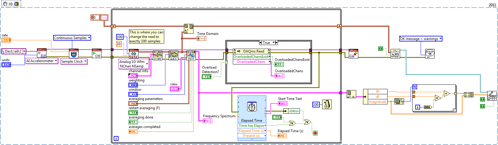
I write a simple program that collect data from a triaxial accelerometer input, convert it to a frequency spectrum, and then save the time domain and the frequency of the waveforms in an external file separated. I don't understand how to set the sampling frequency, however. On the DAQ Assistant, I updated the acquisition mode "Samples continues" and read samples is 2 k, which corresponds to the total number of data points that are collected. How can I program sampling for awhile, it 30 seconds, for example? Wouldn't be better to set up a trigger, as it will continue to collect data up to what I told it to stop?
I also want to save waveform data in a separate file that can be easily seen by other computers that have not installed Labview. I have currently the program put in place to convert a text string of the waveform of the time domain and then save it in a text file or a spreadsheet. It works fine, but I would also like to record the frequency wave, which is a different type of data. How can I do this or is there a better way?
My program is attached. Thanks for your help!
Here's how you can use the shift register to build the table, and also where you can choose to play exactly 100 samples per while the loop iteration.
Brian
-
given high-frequency sampling one at a time
Hello
I'm using LabView 2011 for resistance measurements. The express vi DAQ assistant is placed in a while loop and it acquires 1 sample (on request).
Each sample is acquired, it is compared to a set point. If the resistance value is greater than the set value, a task is executed. If this is not the case, no action is taken.
Now, I would like to increase the frequency of acquisition of say 5 kHz. As before, I wish the DAQ to give each value because it is acquired and compare it with the desired value. However, only one point acquistion is limited by the speed of the while loop (which does not exceed a few Hz per second when I use the software-timer.) If I use 'continuous samples' at 5 kHz, data acquisition does not give these samples one at a time. It seems to acquire until the buffer is full and then released several samples at a time. It is therefore impossible to compare with the set value.
Is it possible to get data at a high frequency and do compare to the set value, one at a time?
The code is simple enough to do this.
But the problem, it all comes down to how fast all of the other code in the loop takes to run.
The first problem is that you use the DAQ Assistant, which provides a lot of extra load in the loop, especially if you don't set it up properly. (And we can't say because no code is set to look at us.
You should try a real code DAQmx where launch you acquisition continuous samples before the loop, acquire exactly 1 sample in the loop. Then close the DAQmx task once the loop ends. See if keeps.
Why do you need to do this? Note that all instant Windows might decide to fly a second or two and go and do something else like a virus check. If you need at that moment (how exactly do you need that?), then Windows is not the right system for this run.
-
To begin with, I am very new to labview and unfortunately on that my first task is to build something rather complicated for a project that my company works. Fortunately it is especially followed rather than control critical processes.
Currently, I have a cDAQ with modules, DI, AO, and TC.
cDAQ-9133
NEITHER 9472
NEITHER 9421
NEITHER 9263
NEITHER 9205
NEITHER 9212
I'm currently running read-write for all 5 of these modules in parallel while loops and analog and digital inputs/outputs modules that all work as expected. Each loop requires 1 sample per channel through the wizard DAQmx etc for each module and I got can interact with all the asyncronosly inputs and outputs which at the moment is the goal. I can switch power switch for each module save memory, or if the need arrives later.
My problem is that the module TC (NI 9212) when tilt on which allows the acquisition of sample 1 loop seems to take much, much longer to collect samples. I have played with different acquisition parameters and can seem to get a continuous flow of data when you use streaming samples, or even when specifying N-samples but I come in questions where the "application cannot catch up with the hardware.
I tried to find an optimal number of samples/sampling, rate, etc I can get an update of temperature more than every 1 to 2 seconds, but if I set the number of samples that are high enough to apparently get a constant flow, what ends up happening waveform graphs seem to lag behind the actual data, and that's where I get errors. I only want 1 sample per channel per cycle anyway. Yet once, all the other modules in the cycle with less than 100ms delay between acquisitions but the module thermocouple ends up being 1-2 seconds. It's okay because in our application temperature should not rise/drop very quickly but its boring nonetheless.
I have the acquisition set up for the same (NI 9212) thermocouple module was like my modules of analog and digital inputs (NI 9205 and NI 9421) take 1 sample every time the task is called so I'm having a hard time understand why do the same for the TC module introduced such a delay. Max sampling rate is supposed to be 95 samples/s/ch, so I guess that the delay must come from call the task over and over again in a loop.
Synchronization and how you have configured the 9212?
In the case of high resolution, it can reach 1.8 samples/s. see page 7 of the plug technique here for rates for the supported modes:
http://www.NI.com/PDF/manuals/374389a.PDF
-AK2DM
-
Sample of SCADA project transmits alarms
Hello
I tried the new sample SCADA project that came with LabVIEW + DSC 2013: file-> Create Project-> projects-> Supervisory Control and Data Acquisition System sample. I've deployed libraries and then ran Main.vi Client and server Main.vi.
If the Client and server are running on the same PC, everything seems to work properly. The customer receives updates the value, and the controls start to flash red if an alarm goes off. However, if the Client and server are on different computers (on the same local network), and then the customer receives that updates the value of the server- it does not alarm, even if the firewall has been disabled on both computers.
How can I get the customer to receive alarms when it is on a different PC in this case?
Thank you!
Yes, it works correctly for me on multiple computers. You can try to use the name of the computer in the Client.ini file for the server instead of the IP (192.168.1.99 in your case) computer?
-
The reading of data acquisition via tcp
Hello
I am building an application that controls an acquisition of data via tcp.
I have a JAVA program that communicate with labview, give a command and data acquisition starts. (So, I read the correct Java data at Labview)
My problem is if I try to read data acquired by data acquisition (continuous sample 1 k samples), I've read strange values.
I transform of double values in the string and send it via tcp.
How can I read it in Java? What type of socket should I use? What is a rate problem?
I also tried to transform small/big-endian byte order, but it does not work.I enclose a sketch of this part of the application.
Please help me, I try for 2 weeks!
Thank you all...I find the solution in the lavag forum.
I post here, if it can help someone.http://lavag.org/topic/16359-sending-LabVIEW-data-via-TCP/page__pid__99983#entry99983
-
Tilt on a random channel USB-6251
Hello everyone
I hope that you will be able to help me with this problem that haunts me more than two years now.
I use a USB-6251 box to acquire 3-way @100kS/s (acquisition of sample of N, N ~ 250 ksps), while simultaneously sending a result to one of the analog channels.
In my application, the period of channel inter is very critical, that is, it must be precisely known (but not necessarily zero, although it would be nice).
Not convinced by the results mediocre I got, I decided to perform a simple test to measure the impulse response (one so distort the channel) between the AO and the first 4 boards of my 6251. To avoid ghosting and keep the 4 AIs isolated from each other, I plugged 4 amplifiers contained in a TL084 IC in follower of voltage configuration to AIs, while feeding their entries with the AO signal outputs.
I sent a Twitter and is its correlation with the acquired signals. The chirp was generating an impulse response "low pass filtered", in order to better appreciate the delays of the fractions of samples in the impulse response (IR).
Some very confusing results: the IRs are randomly (by comparing the various acquisitions) place in the "t = 0" and "t = 1", very rarely to 0.<><1, while="" i="" was="" expecting="" to="" see="" 4="" irs="" "equi-spaced"="" within="" 1="" sample,="" since="" the="" 6251="" contains="" a="" single,="" multiplexed,="">
The same random behavior can be observed by sending a simple sinusoidal signal and by checking that the 4 acquired signals are randomly out of step with the other by exactly 1 sample.
I repeated the same tests in Matlab (using data acquisition and directly call the library daqmx) and Labview 8.2, still getting the same resut. I also tried (in Matlab) only change the sampling rate (as low as 8kS/s) and the number of samples acquired, without any significant change in the results.
So finally, my question is: is there some kind of post processing going on behind the scenes which aims to align the entries, that fails somehow? Or is it because of some bad attitude? Would it be because of lack of samples?
Has anyone else had similar problems with Renault multiplexed?
Any thoughts on this would be highly appreciated
Kind regards
Giovanni
-
Why labview programmers use 10.1 the default frequency instead of a same 10.0 Hz?
It was an issue that was raised during the lab class and no one has an answer for. Any ideas?
I call it the wagon wheel effect.
In the old westerns, whenever a wagon with a Ferris wheel to rays rode by the camera, sometimes the wheel would look like it rolls slowly forward, sometimes slowly propagated backwards, sometimes it would look as if it was stopped.
It is a function of the frame rate of the camera over the period of the cycle of the spokes of the wheel. If we spoke (or more) offers exactly the right distance between a frame of the movie and the next, it would look like the wheel had not moved at all. If he moved a little further than the distance from rotation of we talked, it would look like it rolls slowly forward. If the cart is a little slower, then it would move only less than the distance of a spoke and he would look like the wheel rolls backward.
Same thing with having a periodic waveform (every bump of the sine wave is a spoke of the wheel) and a number of acquisition of samples and data rate equal to a whole number of this period (essentially the frame rate of the camera.) Wagon wheel always rolls forward. The sine wave is still oscillating. But according to the rate of acquisition compared to the wave sinusoidal frequency gives a different appearance to the appearance of this sine wave on the chart.
Experiment and give it a 9.9 Hz sinusoid, you will see that it seems to move backward.
So I think (and this is only a guess) is that whoever designed the express VI gave it a default value of 10.1 Hz to visually simulate on the graph of the sine wave motion.
It doesn't really matter what they chose by default as it is to you that the programmer LabVIEW to change this default setting (whether in the express VI or the wiring in a value) to something that makes sense for your application.
-
Hello
I have a current clamp for model fluke 80i-110 s I need to acquire an analog signal.
I have a NOR-BNC-2111 interface hanging in a PXI 6289 data acquisition card.
I checked that my current clamp is out 100 mv / ampere of current
I used the DAQ LabViews Wizard to configure a channel and I don't seem to be getting the expected response of the data acquisition card.
My input voltage channel is configured as shown below
I'm reading an entry of tension between 09:50 V using a Mode of Acquisition 1 sample (on request). I cycled through all Terminal configurations available but none of them seem to be save with precision input voltage.
Is there something that I am missing on this channel configuration? When I tried to create a channel to the registration system in collaboration with common voltage X Y plots seem to diverge from each other.
Hello smoothdurban,
Since your current clamp is output 100mV/A, he currently works as a resistance of 100 m Ohm (R = V / I = 100mV/1 a = 100mOhm). So my suggestion would be to create a current input analog task in your DAQ Assistant, set your resistance of shunt on 100 m and your minimum and maximum flow. This way you would be directly save the current.
-
external delay time on imaq camera
Hi all
Thanks in advance for any help. I'm sorry for display on such a common mistake, but I was not able to find examples or previous discussion forums that have solved my problem. Information in any form (examples, precedents, suggestions messages) are appreciated.
My problem is that I can not manage to externally trigger the example attached "He'S triggered Ring.vi" without getting a timeout error.
I was acquire images on a Dalsa 1 M 60 camera for a year using finite buffers, externally triggered, but the method of triggering that worked for me this last year is now a failed due to timeout error. I can confirm that my old program acquisition still work and physical relaxation is therefore able to reach the camera very well (g. trigger is identical to what I'm trying with the ring buffer).
The error number is "1074397150 occurred at extracted IMAQ buffer. I spent the time-out of frame, added structures from sequence flat to make sure that things happen in a correct order separate counter in a separate while loop and has recently launched a campaign of the evolution of the parameters in the hope of getting lucky (I kid, but I get this desperate) randomly. I realize that this is probably due to a fundamental lapse in understanding on my part and I would appreciate anyone who can set me straight.
Joined the .vi
See you soon,.
A
Hello
I am pleased to learn that the ring of triggering HL works. It is promising because it proves that the issue doesn't lie not with the framegrabber. I noticed one thing that is the default value, number of buffers in the HL triggered ring example is 10, while the default value is 5 in the low level version. Have you tried to increase the number of buffers in the low level program, and it allows you to run successfully?
-
problem with timing cRio and FPGA
Hello
I develop software for measure the position of a device using some quadrature encoders.
What I do uses the FPGA interface to acquire the position, then send usign real number of the meter to a host pc to create a data file. In the RT environment, I create a table with the position and the time that is acquired and using shared variables I send the array to the host PC.
But I have a problem with the sync. The sampling time is unstable, I use a timed loop to control sampling but after some acquisitions, data sampling period begins to increase, as you can see in the image of attachment file. In the attached picture, I used a period of 250us and after some time gets twice and 3 times longer before you clean the table and begin to create a new table, during the period in 250us again. so the problem is that I should get a stable period in 250us instead of these steps in growing period
You use the table of construction to add new data points? I suggest to use the function "Initialize the array" and "replace the array element. It will reduce the time it takes from the table of the construction.
I can't open your code as I have LabVIEW 2010.
Maybe you are looking for
-
Find some friends does not update my email to Icloud.
One day I had to find friends and he said location is not available. So I looked into it and, as I just recently changed my icloud email, the email has not changed to find friends and I can't use it because my email does not change. advice on how get
-
Product, printer: HP Photosmart A536; Operating system: Windows 8.
After conversion from Windows Vista to Windows 8 I reinstalled my HP Photosmart A536 printer and down loaded the driver of Windows 8 for it from HP. The system identifies the printer but do not print photo even if the program HP doctor and scab print
-
Opening at the same time both submenus
I'm creating an application interface user who have about 10 different menus. Now I need when the user then works with a submenu at the same time, it can open the submenu other belong to the other menu. When I was setting up the structure of the even
-
Advised that PC does not reconise the USB hard drive or extertnal
I have a XP PC. A year ago I was warned when I inserted a USB stick that my PC does not recognize it. a friend told me to download a new driver for it, I went to their Web page and didn't understand where I could find a driver for it. Because he did
-
Notification for feeding area icons network are mising - usual bugs do not help
I know there are a lot of posts with suggested corrections and believe me I've been gong through them for several days but - seems every time that windows update will update my Vista, I lose one or more of the notification area system icons. Currentl