acquisition through VISA & USB scale
Hello
I try to acquisitionning the value of my scale of KERN, via a USB port (the output of the device is RS 232) with the attached vi. My problem is I want to make an acquisition about every hour. If I put a waiting time in my moment of loop than even 1 second, it seems that the device remains set until we ask for it. So more time is running, more the offset is. Any idea on what I am doing wrong?
Thanks in advance for your help :-)
Sylvian
Thank you all for your suggestions. I finally found a way (see VI) attached.
Sylvian
Tags: NI Software
Similar Questions
-
Need a new acquisition of data USB multifunction device
Hello
Currently I use a PCIe - 6321 Multifunction DAQ hardware to control my stepper motor. I need to change the PCIe - 6321 and use the engine with a device for the acquisition of data USB multifunction bit PCIe - 6321. I'm not sure which USB model to select. Can I please get help about the choice of the right MIO USB data acquisition device that works similar to the PCIe - 6321.
Thank you
Bharath J S
The 6212 differs from the 6321 somewhat on the digital side, which probably you use to control your stepper motor. For example, it was only software DIO timed tasks and has only 2 counters with a set of features (e.g. no output meter in the buffer).
Best regards
-
Looking for a way to mount an acquisition of data USB-6008
Anyone has a suggestion for an acquisition of data USB-6008 mounted on a Panel. I use it for a system where it should not be loose. I have a few ideas, but hope that someone smarter already has a good solution.
Thank you
It is not a robust application, but the box will be moved and I don't want it put in the open air. I simply put a velcro pad on the back and the atttaching in this way. Should be all I need.
-
Why I cant remote AimTTi TG2511A func. General through VISA?
Dear members,
I bought the named device and installed the necessary drivers (latest versions) on my win7 64 bit PC.
There is an example in the VI-s which should work fine, but it gives an error.When I try to open the input/output through VISA vi and send a * RST command, the unit shows REM when viewing, but does not reset itself. So do not even VISA and not even the factory examples work...
Can give you advice, what to try to fix this problem? I still keep in touch with the factory, but not all the tips. They tried, it works for them.
I think, there are some conflicts of pilot, or maybe some of them work properly with older versions.
Thank you very much!
ZsikaDid you read my response? You may not send any character endpoint. Add the same character MAX uses (probably \r) with the constant string formatted correctly and try again.
You must also include the function VISA configure Serial Port in your code. You can also consult the advanced feature of series to see how to automatically add the stop character. The basic example should also be considered. This example has the control of the chain properly configured to send to '-' codes.
-
FUZE 8 GB will not play through a usb cable, passage in charge mode
Is it possible to plug a USB cable into the ROCKET and make him play through it? I have an FM transmitter in my car with a remote control, but it works only if connected with a USB cable. I now use it via the headphone jack but want to use the remote control. I just upgraded to firmware hoping it was a bug, but will still support once the USB cable is plugged. Thank you
I'm not sure what you mean by "Play through the USB Cable"
Inside that cable companies have four sons:
Two provide 5 volts, which will load the "rocket" but still allow him to play.
Two others are the USB data lines, which will allow your PC to read and write data files.
While these are connected the "rocket" appears as a storage device and play any music.
There is no audio cable in the USB cable stock.
When I connect the "rocket" in my car, I have only power connected, it plays music very well and recharges its battery too.
Even if the "rocket" is connected to anchor the Sansa, you can not play music if the USB cable is connected to
a computer. There are additional connections in the 30 dock connector line out pins, like headphones
selector and a few pins communications for the remote, but the stock USB cable does not work
touch these extra pins. So unless you have a Sansa dock, or maybe one of the Altec-Lansing dock units.
You probably don't have access to people.
I hope that helped.
LyleHaze
-
Hello!
I recently installed a Pioneer AVH-4200NEX unit, I was super excited to improve my car with the support of CarPlay, and everything works great except for one thing. When I connect my iPhone (6s +) to the unit via a USB cable and a standard phone call, the audio quality is very bad - hail, very downsampled, and metallic sounding compared to the use of Bluetooth via the unit to pioneer for the same phone call (I'm on LTE, using HD voice, although the quality difference is quite noticeable on the calls not HD and on the 4 G calls). I looked for an answer to this question, but the best that I can find mention of limited USB bandwidth and try to juggle than the bandwidth for the rest of the CarPlay experience, although I don't buy not because audio via the iPhone connected with USB playback is just as clear that it is through Bluetooth. So my question is: How can I submit a bug report Apple about this behavior and (b) do you have other CarPlay users also be known this recent problem on a unit of Pioneer NEX (AppRadio included)? It would be great if this is a bug of Pioneer for which they can release a firmware update, I'm just worried that it is a codec problem specified by the CarPlay, so non repairable.
Thank you!
-Seth
Hello served,
Thank you for using communities of Apple Support.
I understand that when you use the USB cable for your iPhone in your car with the audio CarPlay is mediocre. I know how it is important for you to hear your calls clearly. In a situation like this, I recommend the steps described in the following article to help solve the problem.
Configure CarPlay to use with your iPhone
Specifically the section to get help:
Get help
If CarPlay does not work as you expect, here's what you can check. After each step, try to use CarPlay again.
- Make sure that Siri is turned on.
- Restart your iPhone and your car. Depending on your car, you can see the CarPlay home screen when you turn it on. If you do not, look for the CarPlay logo on the screen of your car.
- If possible, connect your iPhone to a different USB port in your car.
- Try a different lightning to a USB cable. Make sure that the cable is certified.
- Update to the latest version of iOS.
- Check the manual using your car. You may need to install updates of firmware for your stereo.
See you soon
-
Communication problem between LabView and acquisition of data USB 6259
I want to monitor a data USB-6259 acquisition using LabVIEW 8.6. However, when you try to create an explicit task (using the DAQ assistant) in order to acquire a signal, I get the message asked supported device found¨. I can see the USB-6259 under ¨Devices and interfaces¨ to the MAX, but when I try to import the configuration data for NOR-DAQmx 8.7.2 in MAX, I get the message ¨Can´t import file configData.nce. File not found¨. I use NEITHER-DAQmx 8.7.2. Any suggestions?
Corneliu
Hi, Corneliu,
This question could be generated due to a corruption of database of MAX. Here is a link to restore the database to the MAX.
http://digital.NI.com/public.nsf/allkb/2C7480E856987FFF862573AE005AB0D9?OpenDocument
Just follow the steps and let me know if that solves the problem.
A greeting.
Jesus.
-
While NI-VISA supports three types of USB pipes: Does control, in bulk and interrupt, this means that we can develop any device driver USB on this three types and we must not any other low level layer of knowledge? For example, if write us raw data, we simply use the essential mode of writing, and then outgoing data usb would be out of our written data.
I do not understand your question.
VISA takes in charge three of maximum 4 eligible different available for USB transfer mechanism. Isochronous is not supported and a transfer with loss that is not interesting to test and measure in any case. It is intended only for audio and video where a few lost packets are not so bad.
All USB devices may support ONLY these four types of transfer. Note that this does not describe WHAT needs to be transferred by using these methods, only HOW the data is transferred.
Each device implements its own mix of commands that can be received by transfer of control (all devices are supported on a certain set of commands on the control endpoint zero for the configuration of the device), in bulk or interruption or a mixture of the three.
If a device does something different than is described in the specification of USB protocol document is not USB conform.
Shane.
-
Greetings,
I have a USB device, I need to communicate with the help of Labview. There is no drivers for this device so I put in place as a device USB of VISA GROSS. I am able to communicate with him, fine, for the most part, but I have problems with data loss.
This device to stream to the host at a rate relatively high (~1MByte/sec) and I have 3 of them I need to get data of continuously. Data is sent in packets of 512 bytes. When calling VISA Read I Specifies the amount of data I want to read from the device (for example 512 000 bytes approximately 0.5 seconds of data) and the data is received without problem since all 3 devices.
My problem is that it takes a little short of time nothing to do with the data I just read and read the next time I do a different reading VISA, I lost the data that should have been included while I was managing the data from the old. I simplified my Labview code so that it doesn't the data analyze a few bytes and paste the rest in a queue to be processed in another while loop, but even this bit of transformation takes a few milliseconds. Milliseconds that few data are lost when I next read VISA.
I think the problem is that USB transfer must be initiated by the host, which means that any buffering must be done in the camera itself, and that this device is not all the buffering. Is this correct? Y at - he tips that I can use to make "continuous play" from a VISA's USB device?
I might be able to shorten the processing time a little more by not doing ANY analysis on the data, just read and paste it into the queue, but even that will probably take long enough I'll miss a few packets of data (each packet is less than 500 of data).
Thanks for your suggestions.
Dave
You can have several USB readings operate in parallel feeding a notifier data. Can manage data notifier later in your code.
I did it with HID before calls to no HID updates were missed.
Shane.
-
Acquisition of data USB-6008 not detected in LabVIEW
Hello
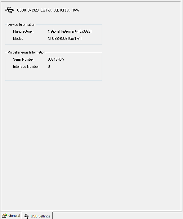
So my USB-6008 DAQ hardware is not available when I do a new task DAQmx (or open the DAQ assistant).
I found this link: http://digital.ni.com/public.nsf/allkb/179BC9B0266168288625722100738C22
I did everything just said but LV still does not detect my USB-6008.As you can see on the image below it is detected by the solution of measurement and Automation Explorer. I don't know how to test with visa test Panel.
After that, I tried to test with the diagnostic utility, and here it does not appear in the list.
I downloaded the appropriate (several times) drivers but still nothing.
Can someone help me with this?
-
Sampling frequency for the output of an acquisition of data USB-6211 card?
Hello-
I use a CGI CMOS FireWire camera to read an interference figure, then using a transformed of Fourier transform spectral interferometery (FTSI) phase recovery simple algorithm to detect the relative phase between the successive shots. My camera has a linear 28 kHz scan rate, and I programmed my phase retrieval algorithm take ms ~0.7 (of a trigger of camera at the exit of the phase). I use the live signal to control a piezoelectric stack, by sending a voltage single sample to the analog output of a data USB-6211 acquisition card.
Send this output voltage increases the time of my loop 4 m, I would really like to achieve a 1 kHz or better sampling rate. Is the problem with my DAQ card or with the processor in my computer? The DAQ cards of NOR can support these speeds?
Thank you
-Mike Chini
Hey Mike,
With USB, your loop rate will be around or under 1 kHz, even on the best of the systems. USB has a higher latency and less determism PCI and PCIe. You can get rates AO one much better sample on a PCI card, potentially a PCI-6221. We have a few HAVE points of reference for targets of RT for PCI, / AO in a loop, you should be able to get similar performance in Windows, but if you do a lot other treatments may suffer from your local loop rates.
Hope this helps,
Andrew S
-
How to reduce the noise in an acquisition of data USB-6251
Hello world!!!
I have a few questions about a system that I have developed using a data acquisition OR usb card 6251. The pressure control system.
First of all, the signals are acquired using an Omegadyne pressure transducer. (Typically, the signals are between 0.1 mV and 38 mV, pressure is between 0 to 50 lb/PO2). The transducer is connected to the usb-6251 daq card (I use pinout of the 1 and 2 for the signal acquisition, also, I have a 100 K resistor between pin 2 and 3) and the card is connected directly to the computer. In addition, I have an omega counter, I use it only to see pressure on the screen. But long term, it will be useless.
One of the problems I have found is the noise, the measured voltage values change much. Even if the figures in the player screen do not change so much... (or do not change)
The system should regulate the pressure so if every second it changes a lot, the system did not work properly. How can I make the technical more similar to that of the meter? In the labview program that I use, I use a block 'base DC', he reduced noisy signals a lot, but not enough that experience, I need more stable values.Thank you
I don't mean in the /manuals of broaching and do not open .doc from unknown sources files (a chart single .png is fine ;-))
However, I guess you already measured in differential mode and the 100 k is a path for the currents of polarization forever
The reason why your counter is stable can be the fact, that she has a generation to filter low pass (on average) with a big enough constant time.
First things to do:
You did it that there is a filter anti-aliasing suitable for your sampling rate?
Read the signal on at least 100 ms (120ms in line 60 Hz) possible higher sampling rate and take a look at the signal (and display a chart as a .png or .jpg image)
This will give you an idea how the signal looks the same. Then you can choose a filter according to your system and the signal or other investigations to do not even catch the noise (groundloops, protection...)
You can use an example on the screws or the testpanel to the MAX for this measure. (Personally, I prefer a similar scope :-))
-
visa usb communication in bulk - several end points
Hi all
I'll put up a spectrometer optics USB2000 + ocean and want to use visa instead of the dll that I had with the spectrometer (I had a lot of stability problems, moreover, this is not supported by the ocean optics and I won't have to pay for the new version). I have documentation for the spectrometer and were able to set the integration time and receive ghosts as quickly that the dll has been able to. But I was not able to read the information of calibration of the spectrometer. All controls use the transfer block, so I use visa read and write to send/receive. I think it's the difference between the spectral data and calibration data, that the data comes from different points of termination. The spectrometer has 4 endpoint addresses (3-PC = IN, 1 PC = OUTSIDE). The spectral data returns to the first endpoint and the calibration data is on 3rd in.
Is there a setting I need to change to read from a different end point? They are all in bulk type according to the documentation. Any suggestion would be appreciated.
Thank you!
Hey gharris,.
It seems that there is a parameter, you can change by a property node that will change reading from what endpoint. If you use a text-based program, the property, you need to change is VI_ATTR_USB_BULK_IN_PIPE. If you are using LabVIEW, follow these steps:
First of all, to ask a VISA property on your block diagram node (really any node property works). Then, right-click on the property node and select Select class-> VISA-> / o Session-> USB Raw. This step can be found in attached below EndpointSS1.png and change the property node to a node property USB Raw. Thirdly, left-click on the property and select settings USB-> pipe in bulk. This step can be found in EndpointSS2.png, attached below. It is the property that defines at what endpoint to read from. To change the value of the present, right-click on the property node and select change all to write, which will allow you to connect to an endpoint value.
-
I send you a picture of samples using usb visa communication. The sample size is 12 bits, due to the resolution of the ADC and the size of the buffer
of USB is 8-bit. The program must divide each sample to two bytes (each sample must
be divided to the valuable part less and more) in order to use the USB buffer. There for each
sample occupies two buffers of the USB and it can send in 32 samples of the signal for each
transaction, because the USB port can just transact 64 bytes set to maximum speed. I have developed a program to rebuild analog signals of these samples.
If I send the table consist of four different signals separated by a few special characters and I have to show four different signlas, separated by special characters. Please suggest me any changes in VI attached to four signals to separate and display. The attached vi is to display a single signal
Hi, you can parse the string and cut with the chain of research/Split. The wire of the output to an indicator of the string string. You can follow these steps to use this feature:
- Add Research/Split String function in the block diagram.
- Thread the string to split at the entrance to a string of the search/Split String function.
- Enter the text that shows where the string should be split at the entrance of the research/Split String function string/char to search .
- Offset, enter the number of characters in the string to pass before the function of research/Split String begins to search text in the Search/char string.
- Connect the substring before game and out of game + rest of string of the function of research/Split String String of indicators or the screws or the functions that accept a string as input.
- Run the VI.
Kind regards
Miguel Fonseca
Technical sales engineer
National Instruments
-
Generation and acquisition at the same time, acquisition of data USB-6356
Hello
I have a VI how is able to read entries with a USB DAQ-6356 and I use a generator of signals 'Agilent 33522 A '. I want to generate and acquire with the acquisition of data.
In fact it works but not well, the frequency is not very stable and does not stop the 2nd loop with 1 (2nd is generating, 1 is Acquire).
Thanks in advance

P.S my VI isn't a state machine true because I need to fight against it at the moment.
OK, so you're at 3 ms/s in writing and reading at 1.25Ms / sec and you wonder why he has a little difference in the frequency set? Ideally, you want to read and write to share a sample clock but by selecting at least the same frequency clock (or one that is one multiple of the other) would go a long way to fixing this source of your error.
The second source of error: you generate a contineous waveform. unless you select 'whole number of cycles' there is a discontinuity when the end is reached at an arbitrary phase and the phase is reset to zero at the beginning of the wave. DAQ assistant writing can "Use Waveform Timing" to adapt its sync settings to the dt waveform and the number of samples.
Maybe you are looking for
-
NB200 - 10 p - cannot install the Inter - problem with SATA driver Storage Manager
Hello :) I installed XP Pro SP3 disk a HARD clean on my NB200 - 10 p.To get to the installation CD, I had to modify the "controller" SATA "from"AHCI"to"Compatibility"modeXP has no sata drivers embedded. Instalation of OS went well, and I installed al
-
Toshiba Cameilio H10 - Question about recording format
Conversion of camcorder high definition help please! -------------------------------------------------------------------------------- I recently bought a Toshiba Camileo H10 what movies in HD 1080 x 720 camcorder. I did several video clips in this fo
-
If I send to my laptop via bluetooth, why not the windows player
hopeferully that my question has not been censured...
-
I need new software for my AIO B109a for 32-bit win8
-
ThinkPad - Z61p drivers for the graphics card?
Hello, I have a laptop Lenovo named Z61p with FireGL V5200 graphics card and my question is if there are new drivers on for her? I ask because I feel as if I'm weak performance in some games that performs well and I think that by using a newer and be