Agilent U2722A linear voltage ramp
I am currently writing a LABVIEW VI to interface with an Agilent U2722A. I want to measure current constantly while maximum increase of voltage of 0V to a defined use specifying the step size and no time (a linear scan of tension).
I downloaded the driver for this device which also includes an example used for output and then take action. My first problem is that when I run this unit VI is to expire. I think that this issue MAY have something to do with the entry "triggered the level". Happened to configure voltage channel VI. I have included the example and the voltage setting channel Sub VI.
My lack of understanding for the other SubVIs (which are based on being passed SCPI commands by VISA as strings) also prevents me from making progress. Especially the scan configures and configure trigger screws
Scanner Confgiure takes the values for the number of points and the timestep. I don't know how I'm supposed to make use of this VI. Should I put the values you want, and then use a loop to pass different values to the chain tension set up with each iteration. Also, how is the measured timestep? I need to set up a trigger to measure the time between the points or the scan function takes care of that? I've included the sweep set up VI as the Timestep VI as well.
Looks like that you've got another error in connection with the IO instrument. Here are some references for this error,
-420, "request not COMPLETED;
This error occurs when you addess the instrument to talk and he has nothing to say.
The most likely causes are:
1. do not send a query. You must send a valid request to the instrument before talking to talk to him. This is true even of the instruments of measurement, such as the 2001 model. You can not get a reading from 2001 until you send him a request.
2 send an invalid request. If you sent a request and still get this error, make sure that the instrument treats the query without error. For example, send a bad request that generates an error - 113, "Undefined header" and then treat the instrument to speak will generate an error-420, "Request not COMPLETED" as well.
3 query invalid due to an invalid command.
Currently I do not have an instrumetn in hand so I can't understand what is exactly what's wrong, but would you mind to paste your code so that we can look into it together?
The most accurate method is absolutely one provided by the material itself. Here is "Interval" in configure Sweep.vi.
Tags: NI Hardware
Similar Questions
-
Multisim: Parameter Sweep of piecewise linear voltage source
Hello
I did a transient analysis of a 4-stage-amplifier with a certain input pulse generated with a piecewise linear voltage source (screenshot 1).
Now, I want to do a sweep of parameter analysis by varying the amplitude of my generated pulse.
What is the right for this parameter? (screenshot 2)
Thanks in advance,
Johannes
Hello
You will not be able to do sweeping device/model parameters because the Amplitude of a pulse source is not actually a device/model parameter.
For this, use the parameter of Circuit of Mutlisim feature. See the circuit attached for reference.
I defined a new Circuit parameter (view-> parameters of the Circuit) called "Level" with a default value of 1.
I assigned this setting to the "Pulsed value" parameter of the element of impulse voltage source.
In the dialog parameter Sweep, I chose the Circuit parameter as the type of the parameter I want to scan, and then I selected the parameter 'level '.
I would like to how it works for you.
-
Hi all
I am a beginner on LabView and have written a program to generate the next ramp below. Using the graph, it seems to work, however when I plug a scope or a voltmeter to the map, I see no output. Why?
Riclambo-
You will not be able to see anything in the scope because you run the program once.
To allow you to see something when you plug a voltimeter on your Board, you will need to place a while loop.
Since you are a beginner to LabVIEW I suggest using the screw Express (in this case a DAQ assistant output). In this way, you can configure your data acquisition for output on a specific channel of the Board you are using. Don't forget to select continuous samples, otherwise you will be not able to see anything when you connect or scope or voltimeter.
If you want to leave the service with the same appearance as the one you sent, right-click on the Express VI and select "generate the DAQmx Code."
Hope this helps
Best regards
-
Hello
I'm totally new to LabView using Labview 8.6.
I have a PXI-6704 and on three channels, I should generate a ramp between 0V and 840 mV less than 1 ms, then the signal must remain constantly at the 840 mV. This signal will begin some on-chip oscillators.
I checked the other kind of similar examples as well, but as it's my first experience in LabView I really understand many of them.
Please can someone help I have to use to get the EXPECTED signal? Or if someone has a vi to do this...
Thank you
Kriváň
Help > examples > entry & exit hardware > DAQmx.
-
Non-linear voltage with current variance
[10/07/2014 edited by moderator as requested]
I'm trying to measure the design resistance of the voltage across my test using NI9205 sample. I have a power supply current constant and 30 cm of wire across copper as connectors to my example. I'm exploring various levels from 20 to 500 my.
However, the resistance or voltage/current ratio do not seem to be constant on current values. Current increase seem to increase the resistance of .01ohms.
I change the lines in my daq between 200-1-5 a 10 V.(+-) of heat due to the current, and changes in the sample of it are not a factor. Is that an offset voltage when changin ranges that affects it? I use the daq with no custom scale Wizard. I do, however, collect samples from 1000 to 1000 Hz and their average.
Tried to use 4 wire measures?
0.01 ohm in 30cm copper wire... seems reasonable...
so: two sons for the current and two sons for the measurement of voltage (differential). Guess the image below that is screwed is current and voltage

-
Hi all
I am a beginner on LabView and have written a program to generate the next ramp below. Using the graph, it seems to work, however when I plug a scope or a voltmeter to the map, I see no output. Why?
you posted this forum instead of the labview Labwindows forum. You probalby get a faster response there.
-
PIECEWISE LINEAR VOLTAGE Source BUG
I want to source PWL allows to analyze signals from my digital oscilloscope.
File MEANDR.txt contains 5000 points of voltage (mV) in the time domain.
(1) if I'm going to use this file with the option 'Use data directly from files' there will be no signals at the output of the source.
(2) if I go use the option "enter data points in the table---> Initialize the file" and press the button "Run the Simulation" Multisim breaks down... but it starts working properly if I'll burn the original file of 5000 points to 2000-300 points. (File MEANDR_MODIFIED.txt)
You can fix this bugs?
Thank you!
Hi, ZG,.
Your data will give Multisim a problem because of the format, Multisim expects the tension and the time of two columns. On the column of time data range from 1 to 5000 so Multisim will have to simulate for more than an hour and in the world of simulation that is an eternity. I changed the data so that Multisim simulates only up to 5 sec. Your column of tension is supposed to be in mV on each line, you will need to place a mili at the end otherwise Multisim going out KV. Using Word and Excel, I changed your data to something that Multisim may include and the file is associated.
-
1V - 5v linear output using power supply 5v, voltage divider, and variable resistance
How can I get 1v - 5v output linear using power supply 5v, voltage divider, and variable resistance?
Have the you wired as an attachment? Using my schema, you can calculate the current flowing through the pot based on the fall of the tension in the pot
4V / 10Kohm = 0.0004
Kirchhoff's current law, we know that the same current flows through the circuit so now we can calculate the leg below the wall, based on the current and the fall of desired voltage across the resistance
1V / 0.0004 A = 2.5 K Ohm
My scheme maintains the current flowing through the circuit of constant, so the voltage divider must never change. Assuming a linear pot, you will get a swing of such linear voltage as measured at the wiper. If you wired the pot, a different way, then more then likely, you change the total resistance of 5V ground that would have the common effect that would effect the tensions.
-
How to set up breakpoints with a with a PCI-7344 linear position sensor
Hello
I'm trying to implement an algorithm of scanning for a piezo Nanonics 3D scene, who should synchronize with a card counting (PCI-6602) using breakpoints on the movement card (PCI-7344). The Nanonics Stadium has two position sensors (just for x - y) gives me a linear voltage variable according to the position. Nanonics connected these sensors for the two first entries analog motion motion card connector.
Now I intend to use breakpoints to synchronize the digitization step to a card counting (probably using a RTSI cable), but I got the impression that this can be done by using the entries of each individual axis encoders, no do not using the analog inputs. Could someone comment on that? Explanations or advice would be greatly appreciated, thank you very much.
Kind regards
DFD
Hey, DFD,.
I believe that the answers to your question.
Kind regards
A. Zaatari
-
Requirements for data aqusition for body MeltMC
Hello.
Let me Preface this post with the fact that I don't know anything about the material.
I'm trying to compile something that will be used to raise the temp of body at different points on a body of people on
several hours. The device must be relibable, but I'm also looking for something that I myself will be able to understand.
A similar study used the following.
16 Thermistors (type MA100GG;) Thermometrics, Edison, NJ) connected by a linear voltage divider (10 resistors k. ± 5% accuracy)
BNC-2090 A/D Board
LabVIEW.
To reduce the impact of failure of wire, thethermistors were connected to the acquisition system of data with a 28 gauge wire.
16 voltage dividers were organized in parallel, and the circuit was fed to 0.5 V (power supply model PS280;) Tektronix, Inc., Beaverton, OR) to minimize
(self-heating thermistor< 0.01°c).="" data="" from="" all="" 16="" channels="" were="" simultaneously="" collected="" at="" 1="" hz,="" and="" the="">
adjustment of the curve was used to calculate the temperature of the measured output voltage.Please let me know if I can move it a more appropriate Board.
Thanks, J
Hello J,
A set of material for 16-channel thermistor.
All of the following materials is recommended for this requirement at lower cost:
SHC68-68-EPM cable and 1.PCI - 6221, http://sine.ni.com/nips/cds/view/p/lang/en/nid/14132
2.SCXI - 1349 Adapter PCI-6221 and SCXI, http://sine.ni.com/nips/cds/view/p/lang/en/nid/1627
3 SCXI-1503 and 1306 16-channel thermistor, http://sine.ni.com/nips/cds/view/p/lang/en/nid/204198
You can use LabVIEW SingalExpress that comes with the equipment to record the data, or if you want to do further analysis, LabVIEW can also help.
You don't need to calculate the temperature of acquired resistance.
Software will display a temperature directly, but you must enter a correct setting of the specification of the thermistor.
Sincerely, Kate
-
Questions with more than 16 channels in daqmx
I've implemented a .VI (from the pieces of the help on the forum) that I use with the NI USB-6225 to collect and record anywhere voltages 1-30 or more 4-20mA sensors (pressure, linear voltage,... etc.). I tried to implement the .VI to make it user-friendly so that a person could name each channel, as well as to set the duration record and frequency (ie the number of samples). After the data were recorded, the .VI generates a time-stamped PDM file, a timestamped LVM file as well as a time-stamped LVM file for an average of all voltages on each channel.
The problem, I noticed that whenever I have more than 16 channels activated, the saved values for channels 17 and higher pressures are wrong. For example, the output voltages of 1 to 16 channels of a tension of 1.0 to 5.0 (which is expected) and 17-30 channels is negative or very small (0.100 volts). I know that the NI USB-6225 is working properly because I created a simple .VI which simply uses the DAQ Assistant ouptut 30 channels on a waveform graph and all channels of reading in the range I'm waiting (1.0 to 5.0 volts).
To me, it seems that there must be something in the DAQmx (as opposed to DAQ Assistant) I use my .VI who questions whenever I try to save more than 16 channels. I just don't understand enough of labview to understand what may be the cause of this problem and I was hoping someone could point me in the right direction
As you have not joined in the work programme, it is impossible to tell what you did differently. In this program, you do not specify the configuration of the inputs (simple nerve or diff).
p.s., The program is bad need of major cleanup. Keep the program to a single screen. Simplify.
-
The SCXI-1530/1531 devices support
Hello
I found confusing information on the SCXI-1530 support software. Now it is entirely supported by the Traditioanl DAQ and DAQmx?
I found that some document said that "DAQ traditional only when you are using an SCXI-1530, SCXI-1531 or SCXI-1540 device with accelerometer, linear voltage differential transformer (LVDT) or the virtual channels Rotary variable differential transformer (RVDT), which are not supported by NOR-DAQmx.» It should be outdated information?
Thank you
Hi Oly,
To be sure, it would help if I knew what document you look. However looking at the Readme for DAQmx looks the SCXI-1530 is supported only for accelerometers and microphones, which means that the LVDT and RVDT task are not available.
NOR-DAQmx 9.0.2 ReadMe
http://FTP.NI.com/support/softlib/multifunction_daq/nidaqmx/9.0.2/Readme.html
Hope that helps,
Thank you
Scott M.
-
I am trying to write a simple program in c# (.NET 4.0) to control a Keithley 2400 SMU by VISA GPIB and I'm unable to switch to the program to wait as the demand for services which the Keithley send at the end of the scan.
The scan is a scan of simple linear voltage controlled internally by the unit Keithley. I have the device configured to receive a ServiceRequest signal at the end of the scan, or when compliance is reached.
I am able to send orders to the SMU and read data buffer, but only if I manually enter a timeout between the scan start command and the command to read data.
A question that I have is that I'm quite new to c# - I use this project (some parts of my code LV Portage) to learn it.
Here's what I have so far for my c# code:
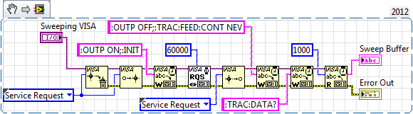
using System;using System.Collections.Generic;using System.Linq;using System.Text;using System.Threading;using NationalInstruments.VisaNS;

private void OnServiceRequest(object sender, MessageBasedSessionEventArgs e){    Console.WriteLine("Service Request Received!");}

// open the address
Console.WriteLine("Sending Commands to Instrument");
instrAddr = "GPIB0::25::INSTR";
mySession = ResourceManager.GetLocalManager().Open(instrAddr);
// Cast to message-based session
mbSession = (MessageBasedSession)mySession;
// Here's where things get iffy for me... Enabling the event and whatnot
mbSession.ServiceRequest += new MessageBasedSessionEventHandler(OnServiceRequest);
MessageBasedSessionEventType srq = MessageBasedSessionEventType.ServiceRequest;
mbSession.EnableEvent(srq, EventMechanism.Handler);

// Start the sweep (SMU was set up earlier)
Console.WriteLine("Starting Sweep");
mbSession.Write(":OUTP ON;:INIT");

int timeout = 10000;             // milliseconds
// Thread.Sleep(10000);          // using this line works fine, but it means the test always takes 10s even if compliance is hit early
// This raises error saying that the event is not enabled.mbSession.WaitOnEvent(srq, timeout);
// Turn off the SMU.Console.WriteLine("I hope the sweep is done, cause I'm tired of waiting");
mbSession.Write(":OUTP OFF;:TRAC:FEED:CONT NEV");
// Get the data string data = mbSession.Query(":TRAC:DATA?");

// Close session
mbSession.Dispose();
All the foregoing is supposed to imitate this LabVIEW code:
So, any ideas on where I'm wrong?
Thank you
It turns out that I need to activate the event as a queue rather than a Manager:
mbSession.EnableEvent(srq, EventMechanism.Handler);
Must be:
mbSession.EnableEvent(srq, EventMechanism.Queue);
Source: the documentation under the heading "remarks". It was a pain to find documentation about it... NEITHER needs to make it easier :-(.
With this change, I also don't need to create the MessageBasedSessionEventHandler.
The final, labour code (with fluff like the namespaces and classes deleted) looks like:
rm = ResourceManager.GetLocalManager().Open("GPIB0::25::INSTR");
MessageBasedSession mbSession = (MessageBasedSession)rm;
MessageBasedSessionEventType srq = MessageBasedSessionEventType.ServiceRequest;
mbSession.EnableEvent(srq, EventMechanism.Queue); // Note QUEUE, not HANDLER
int timeout = 10000;// Start the sweep
mbSession.Write(":OUTP ON;:INIT");

// This waits for the Service Request
mbSession.WaitOnEvent(srq, timeout);// After the Service Request, turn off the SMUs and get the data
mbSession.Write(":OUTP OFF;:TRAC:FEED:CONT NEV");
string data = mbSession.Query(":TRAC:DATA?");
mbSession.Dispose();
I hope this helps future programmers.
-
Hello
I'm trying to use python (with types) to control my USB-6009. The goal is to write an analog voltage and then read the voltage across an entry with the possibility to change the number of points on average and the number of times that it is repeated (sweeps) averaged analog analog input Board. The problem is that, as we increase the number of times the voltage ramp is repeated (scans), we get a time-out error (call nidaq failed with the error-200284: ' some or all of the requested samples are not yet acquired). This value confuse us because the scans are in a larger loop and the function of data acquisition should be the same if there is 10 scans (work) or 1000 scans (crashes). Any ideas would be greatly appreciated. I have included the code below for reference.
import types
Import numpy
the import of time *.
import of the operator adds
NIDAQ = ctypes.windll.nicaiu # load the DLL
##############################
# Configuration of the typedefs and constants
# to match the values of
# C:\Program NIUninstaller Instruments\NI-DAQ\DAQmx ANSI C Dev\include\NIDAQmx.h
# Settings for scanning
aoDevice = "Dev2/ao0".
aiDevice = "Dev2/ai0.
NumAvgPts = 10
NumSweeps = 50
NumSpecPts = 100
filename = "12Feb15_CO2 Test_12.txt".
Readrate = 40000.0
Sample rate = 1000
StartVolt = 0.01
FinalVolt = 1.01
voltInc = (FinalVolt - StartVolt) / NumSpecPts
# Typedefs
Int32 = ctypes.c_long
uInt32 ctypes.c_ulong =
uInt64 = ctypes.c_ulonglong
float64 = ctypes.c_double
TaskHandle = uInt32
# constants
DAQmx_Val_Cfg_Default = int32(-1)
DAQmx_Val_Volts = 10348
DAQmx_Val_Rising = 10280
DAQmx_Val_FiniteSamps = 10178
DAQmx_Val_GroupByChannel = 0
##############################
def CHK_ao (err):
«"«a simple routine check error»»»
If err<>
BUF_SIZE = 100
buf = ctypes.create_string_buffer ('\000' * buf_size)
NIDAQ. DAQmxGetErrorString (err, ctypes.byref (buf), buf_size)
raise RuntimeError (' nidaq call failed with error % d: %s'%(err,repr(buf.value))))
If err > 0:
BUF_SIZE = 100
buf = ctypes.create_string_buffer ('\000' * buf_size)
NIDAQ. DAQmxGetErrorString (err, ctypes.byref (buf), buf_size)
raise RuntimeError ('nidaq generated WARNING % d: %s'%(err,repr(buf.value))))
def CHK_ai (err):
«"«a simple routine check error»»»
If err<>
BUF_SIZE = NumAvgPts * 10
buf = ctypes.create_string_buffer ('\000' * buf_size)
NIDAQ. DAQmxGetErrorString (err, ctypes.byref (buf), buf_size)
raise RuntimeError (' nidaq call failed with error % d: %s'%(err,repr(buf.value))))
def Analog_Output():
taskHandle = TaskHandle (0)
(nidaq. DAQmxCreateTask ("", ctypes.byref (taskHandle) "))
(nidaq. DAQmxCreateAOVoltageChan (taskHandle,
aoDevice,
"",
float64 (0).
float64 (5).
DAQmx_Val_Volts,
None))
'''
(nidaq. DAQmxCfgSampClkTiming (taskHandle,"", float64 (Samplerate), ")
DAQmx_Val_Rising, DAQmx_Val_FiniteSamps,
uInt64 (NumAvgPts))); # means that we could turn into this growing streaming and playback
'''
(nidaq. DAQmxStartTask (taskHandle))
(nidaq. DAQmxWriteAnalogScalarF64 (taskHandle, True, float64 (10.0), float64 (CurrentVolt), None))
NIDAQ. DAQmxStopTask (taskHandle)
NIDAQ. DAQmxClearTask (taskHandle)
def Analog_Input():
global average
# initialize some variables
taskHandle = TaskHandle (0)
data = numpy.zeros ((NumAvgPts,), dtype = numpy.float64)
# now on the program
CHK_ai (nidaq. DAQmxCreateTask ("", ctypes.byref (taskHandle)))
CHK_ai (nidaq. DAQmxCreateAIVoltageChan ("taskHandle, aiDevice," ",)
DAQmx_Val_Cfg_Default,
float64(-10.0), float64 (10.0).
DAQmx_Val_Volts, None))
CHK_ai (nidaq. DAQmxCfgSampClkTiming (taskHandle,"", float64 (Readrate), ")
DAQmx_Val_Rising, DAQmx_Val_FiniteSamps,
uInt64 (NumAvgPts)));
CHK_ai (nidaq. DAQmxStartTask (taskHandle))
read = int32()
CHK_ai (nidaq. DAQmxReadAnalogF64 (taskHandle, NumAvgPts, float64 (10.0),)
DAQmx_Val_GroupByChannel, data.ctypes.data,
NumAvgPts, ctypes.byref (read), None))
#print "%d points"%(read.value Acquired).
If taskHandle.value! = 0 :
NIDAQ. DAQmxStopTask (taskHandle)
NIDAQ. DAQmxClearTask (taskHandle)
average = sum (data) data.size
Thank you
Erin
This forum is for questions of LabVIEW .
-
Entry of absolute encoder PWM w / 6008
Hi, I'm quite new to the DAQ world so please be easy on me.
Well basically, I have acquired a free 6008 and want to use it to track the absolute deviation of angle of a device I have.
My scope involves the use of a labtab (USB only), as well as a range of measurement 0-90 degrees with an accuracy of 1 degree at most.
So I came to the conclusion that I have to get an absolute encoder.
Watching the encoders and their respective exits, I found the following: SSI, Linear Voltage (0-5 Volts) and PWM
I have falling SSI my list because it seems a PCI data acquisition card is a requirement, and the linear voltage is all simply not precise enough, because the encoder outputs (0.056 volt/deg) and the 6008 can be read only with accuracy intervals (0,138 volt). Which means (2.484 degree/interval), I think.
in any case, the last style of output that I found was the PWM signal.
The encoder http://usdigital.com/products/encoders/absolute/rotary/shaft/ma3/
If I have good outings (at intervals micro-sec 1026), where the duration of the pulse is the position of the encoder. (1026 counties/revolution).
So I guess I have to be able to read the pulse of the order (1 micro-sec) for (1 head).
My question is whether or not the 6008 is able to acquire the data for my use in LabView.
Counter the 6008 says its able to detect more than (0,1 micro-sec) pulses.
Does this mean the 6008 so capable of doing the job?
Any help is grateful, as I have very little experience with LabView or DAQ instruments.
Thank you.
It is a limitation just to the meter of a USB-6008. What you describe with 2 counters is actually very close to what we do for measures high frequency on our complete recommended counters. The pulse actually measure that requires only one meter on our E-series, M-Series devices, meter Timer and X-series.
In regards to the analogue output of the absolute encoder, I think you should be ok with the resolution. The output of the encoder is 0 to 5V. The typical accuracy on the 6008 for this interval is 4.28mV for differential connections. Step for each degree size is 5 /(2^10) = 4.88mV. Thus, it seems that you will be able to get a precision less than 1 degree.
If you need better accuracy or would prefer to make the PWM output type, I would look at our M-Series USB for a portable data acquisition solution. Let me know if you would and I'll give you a few recommendations.
Regads,
Paul C.
Maybe you are looking for
-
Downgrade macOS Sierra El Capitan question
Hi all earlier today, I upgraded my Mac mini (end 2012) to the latest version of macOS Sierra. After 1 hour of use, I realized that many of my plugins FCPX were not working. I contacted the developers, and they said does not update the plugins and th
-
HelloI have a laptop Equium L350 and for a few months, whenever I restart the laptop or start the computer bleeps it about 15 times before you start windows vista. I don't know what this means, but when she starts the function click on the touch pad
-
Qosmio G10-105: standard VGA need driver for Vista
Hello I want software for standard VGA graphics adapt nVIDIA GeForce Go 6600 for Vista Please help me
-
My freebox not want pa my printer
My frebox won't recognize my epson while before Yes
-
I am trying to install a program, called yourself in shape. I had no problem installing this in 3 or 4 computers, but now I have problems with my new vista computer, which makes me think it's a matter of vista. about 3/4 of the way by installing, I