Entry of absolute encoder PWM w / 6008
Hi, I'm quite new to the DAQ world so please be easy on me.
Well basically, I have acquired a free 6008 and want to use it to track the absolute deviation of angle of a device I have.
My scope involves the use of a labtab (USB only), as well as a range of measurement 0-90 degrees with an accuracy of 1 degree at most.
So I came to the conclusion that I have to get an absolute encoder.
Watching the encoders and their respective exits, I found the following: SSI, Linear Voltage (0-5 Volts) and PWM
I have falling SSI my list because it seems a PCI data acquisition card is a requirement, and the linear voltage is all simply not precise enough, because the encoder outputs (0.056 volt/deg) and the 6008 can be read only with accuracy intervals (0,138 volt). Which means (2.484 degree/interval), I think.
in any case, the last style of output that I found was the PWM signal.
The encoder http://usdigital.com/products/encoders/absolute/rotary/shaft/ma3/
If I have good outings (at intervals micro-sec 1026), where the duration of the pulse is the position of the encoder. (1026 counties/revolution).
So I guess I have to be able to read the pulse of the order (1 micro-sec) for (1 head).
My question is whether or not the 6008 is able to acquire the data for my use in LabView.
Counter the 6008 says its able to detect more than (0,1 micro-sec) pulses.
Does this mean the 6008 so capable of doing the job?
Any help is grateful, as I have very little experience with LabView or DAQ instruments.
Thank you.
It is a limitation just to the meter of a USB-6008. What you describe with 2 counters is actually very close to what we do for measures high frequency on our complete recommended counters. The pulse actually measure that requires only one meter on our E-series, M-Series devices, meter Timer and X-series.
In regards to the analogue output of the absolute encoder, I think you should be ok with the resolution. The output of the encoder is 0 to 5V. The typical accuracy on the 6008 for this interval is 4.28mV for differential connections. Step for each degree size is 5 /(2^10) = 4.88mV. Thus, it seems that you will be able to get a precision less than 1 degree.
If you need better accuracy or would prefer to make the PWM output type, I would look at our M-Series USB for a portable data acquisition solution. Let me know if you would and I'll give you a few recommendations.
Regads,
Paul C.
Tags: NI Hardware
Similar Questions
-
Read an absolute encoder in cRIO 9076
Hello
I try to use cRIO 9076 and NI 9401 to read an absolute encoder (http://www.gpi-encoders.com/PDF/A58.pdf). I hope that it is possible. Please can someone advise if there are any example or a tutorial that explains how I can deal with the digital input data to get an output of numeric position? Thank you.
Hello:
Are you using the A58-12 encoder? (It's the only one that looks like it will work with the 9401). If so, it returns data using the series SSI Protocol.
You will need set up an output clock and the input of the 9401 SSI data line. For the reading of the data, there is an example of FPGA SSI on the community related to this knowledge base Article.
Hope that helps out!
-
Connect an SSI absolute encoder to a DAQ card
Hello, everyone
I try to connect four encoders of DAQ cards. Two of them are in quadrature encoders and the rest two absolute encoders. I'm guessing that connects the two quadrature encoders to both timers/counters on the card. But what of the SSI absolute encoders? Anyone can give a clue? Thank you very much.
Either way, I am using PCI-6251 and xPC Target.
Pengfei
Hi Pengfei,
If you do not use our driver so I don't know if this is supported, but here's how I would do it using DAQmx...
According to the features of calendar defined page 10 specifications page, 500 ns is the minimum period for almost all relevant parameters:
Period of the CLK line semi
Time between the CSn and the first edge of the clock
The CSn pulse width
Well, it makes sense of the clock of your 2 MHz. You need produce waveforms of the following two, each cycle would be clock to 18 bits of data (12-bit encoder and 6 status bits). The total duration of the cycle ends up being long 38 samples and would take 19 microseconds to execute (if updated to 2 MHz).
CSn 1 0 0 0 0 0 0 0 0 0 0 0 0 0 0 0 0 0 0 0 0 0 0 0 0 0 0 0 0 0 0 0 0 0 0 0 0 0
CLK 1 1 0 1 0 1 0 1 0 1 0 1 0 1 0 1 0 1 0 1 0 1 0 1 0 1 0 1 0 1 0 1 0 1 0 1 0 1
The actual binary data to write to the card depends on what lines you use. For example, if you use p0.0 to CSn and p0.1 for CLK, table you would need to write would be the following:
3 2 0 2 0 2 0 2 0 2 0 2 0 2 0 2 0 2 0 2 0 2 0 2 0 2 0 2 0 2 0 2 0 2 0 2 0 2
The bits of the U8 number correspond to the 8 rows on the port.
You will need an example of clock for your task source. I suggest to use Freq Out on the 6251. In DAQmx, it is programmed in the same way as a meter output. You would set this up as a continuous meter to 2 MHz output. Indicate on your task to use ' / Dev1/FrequencyOutput "as the sample clock source (not necessarily Dev1, but regardless of the name of your device).
You would physically signal port thread 0 CLK in PFI lines and use it to sample a DI task so that you can read back your data. You can enjoy on the falling edge of the CLK to allow 500 ns for the value to be set (the maximum duration of your sheet is 394 ns). The only drawback to this is that you are not sampling the parity bit, but apparently not that it is a problem unless you plan to use it.
Once you get the bits, you must translate that into an actual position. When you call DAQmx Read, you will have an array of values. The first value of each cycle is a disposable (look at the waveform to see why). The next 12 items of any cycle would be the 12 data bits, next 5 bits of State. As I mentioned earlier, the parity bit would not be sampled because of the decision of the sample on the falling clock edge (again, you can refer to the waveform to see why this is the case).
You'll want to convert the 12 data bits of the table in a single 12-bit integer, then multiply by (360.0 / 4096) to get the position in degrees. I don't know what development environment you use, but this type of data manipulation must be achievable. For example, LabVIEW has a Boolean array of numbers feature that would be very helpful here.
I hope that helps!
Best regards
-
Selection of encoder to use with NI PCI-6221 for a project of inverted pendulum
Hi, I'm a mechanical engineering student is his last years, for my final project I do an inverse pendulum system, the University already offered me this data acquisition card which is a NI PCI-6221, and I have to get the other components (motor continuous, encoders, cables, servoamplificateurs, etc.).
My concern is to choose the right encoder so I have no problem... I was told that the best way to measure the position of the carriage uses an absolute encoder mounted on the motor shaft and some incremental encoders for measurement of angles of clock, but I don't know if the 6221 can handle this kind of data to an absolute encoder, and if so, what are the main parameters for selection? as the format, the number of bits.
In the case where it doesn't work I have to go with the option of incremental encoders for both measure the position of the carriage and the angle of the pendulum, I believe the 6221 can manage entries in quadrature encoders, there´re a lot of examples of this, but since models of incremental encoders are wide enough there´re some features that I worry about : frequency vs the sampling frequency response and the output type.
I found a catalogue which includes two types of digital incremental encoders said their models have 300 KHz frequency response, being the only differences, the output and food, anyway the 6221 can handle this freq resp? sampling rate of the card being 250 kech. / s, would there be any conflict?
They offer two types of output: TTL/74LS04 and line pilot, and even if I go further with the hohner encoders they have the following outputs/freq RESP: RS-422 (TTL compatible) / 300 KHz, push-pull differential/200 KHz, NPN Open Collector/100 KHz and push - pull without complementarity/200 KHz.
Any help would be well received

PD: I don't know if a similar topic has already been posted, I'm again like this... I searched in other posts, but found nothing,
-
Encoder DI only fires once when I start
Hi all
I have a 9172 DAQ (USB) with a Module of current analog 9203 and a digital input Module 9401. I try to get 5 force vs position slide on a press.
The DI is a hung absolute encoder that works great and sends the values of encoder back.
AI has 5 sensors of force hanging and works very well when the press is running.
The problem is when I try to use both the DI and GOT both (I have a trigger on the set of DI at a value of 7000) begins it to capture the forces, but I only get the 1st encoder value in the file.
Well, any help would be appericated. I am a newbie in Labview. I have included my file.
Thank you
Michael
Hi Michael,
I guess you can use a business structure that determines when the encoder values are stored and integrated in the table, while the case of false past nothing through. Your current DI acquisition is a sample on request and your measurements of the N samples, 300 at a rate of 32 kHz. This means that when you read your DI value greater than a number, it will stop and take 300 samples before writing and iteration again. I'm not sure how much encoder values you want to save, and when, but you either will have to make a similar finished sample on your DI to obtain values more by iteration or build a sample in a table as mentioned both liked the top.
9425 module is just another DI module, so it shouldn't affect the way in which you will need to code. The main difference between the two modules is in software timing equipment schedule vs. You use avoiding in your code, so no prejudice to the performance should be considered.
-
Frequency of maximum output with USB-6008
I have a digital circuit containing 3 exits, 3 inputs digital and analog 1 entry in labview with my USB-6008. When I connect to the entrance (via the DAQ assistant) analog, the output frequency is reduced to a maximum of 27 Hz, but I need 50 Hz. is possible to do?
Ah. You'll need a DAQ better than the 6008, to do.
There is no train generation feature buffering or the pulse on the 6008. The outputs are all timed by the software, you cannot build a table and tell the 6008 in the output array. Out of the 6211 must be able to produce this signal. Series X-series Renault will do what it takes; the USB-6341 is probably your best option.
-
Hello world!
I have a project with USB 6008. I want to count impulses (for special features: count the pulses of the encoder) use USB 6008. I wirite with DAQmx to test a simple. But it do ' t run. Please see and help me to do this exercise. I just borrowed 6008 USB so I don't have any experience with USB 6008. Thank you! It's funny.
Looking at the PFI0 manual (pin 29) is correct and I don't see anything wrong with the code and example should work. I have a M-series card, not a 6008 and it works for me. This error code is meaningless if. Are you sure it's the number?
-
Get samples of the clock machine (NEITHER with NOR cDAQ-9172-9422)
Hey guys
I'm trying to produce data for the position of a 1000 Hz all about stamping press with an absolute encoder which is connected to the NOR-DAQ.
Two not that I am trying to program, but can not understand:
(1) use a hardware clock to trigger the acquisition of the data at the selected speed
(2) synchronize the three data acquisition modules I have to ensure that all data are received at the same time
the material I have does not seem to have any counters. A few examples that I read would not go because of this.
Any thoughts? If there is some examples/tutorials about this problem that I have missed please let me know.
Thank you
Hey, Rohan,.
Thanks a lot for your help. I was talking to a National Instruments process engineer yesterday and it me that the problem was the vi calendar clock source option - instead of using AI/SampleClock, I had to use the time base of 100 kHz clock that did not appear in the list until I checked the option "ListAdvanced Terminal" in the name of e/s filtering dialog box. You must right-click the constant/control of the source of the clock and select I/O name filtering to open this dialog box.
Thanks for all your suggestions, I'll try to apply it and check the performance.
Nik
-
So, it's a little awkward for me, I've been a professional programmer for almost a decade now, but I'm unable to start even with developing my first plugin. I'll try to be as complete as possible in my description, in which case the problem is in the version of VS, misconfiguration, or like that stupid user error. Is the short version of my problem: I can't even generates the famous skeleton project.
I have AE CS3, so which is the SDK I downloaded and I develop on Win 7 64 using Visual Studio 2010 Express Edition.
I copied the project skeleton and renamed all the files (changin skeleton in my name of the project), then do a case sensitive search-replace ProjectName skeleton and SKELETON of PROJECTNAME. I did the renaming via Visual Studio find and replace, without a solution open, looking across *. * in the Projname directory. Then I opened the sln file and it improved the format VS 7.1 to 10 VS.
I then looked in the parameters of the project and concluded that the other directories Include several entries in the form of "... /.. '. /.. ' / Include '. I had put my copy of the skeleton in a directory where I normally keep my programming projects (IE, not in the SDK directory), so I changed all these entries to absolute paths. Then, to be double sure, I added the SDK directories "Include" and "Useful" for "Directories Include" project.
When I Isaiah to compile, I get two errors, saying: he can not build the PiPL.r and PiPL.rrc files (I don't remember the file name right something like ProjectName_PiPL.*) because it can't find the specified files. The caviggia file exists, but not the file .rrc (a .rc file done, but not a .rrc). In addition, I can't find anything on a .rrc file in the documentation and cannot find any information on basic information of type "How do I Setup build the SDK in Visual Studio" in the documentation or on the web. I also looked for the custom build steps that are trying to build these files, but cannot find them. Before each file, the output window says something like "Building the PiPLs" and when I search for this text, it is in the project file, but when I check the steps custom build and events sections in the properties, they are all empty.
I was able to create the effect that I desired for most using expressions in AE, but I could do better as a plugin, and I am really angry that I can't solve this fundamental problem.
Thanks for listening!
Usually, the PiPLs have directories of the different path and they are built using the custom build tool. If you get an error "Betty file is missing", then right-click on the PiPL.r file and go to step (I'm not on a machine windows at the moment, so not sure that one) command line generation / custom and then you can see the arguments that are used to compile the PiPL. So to change paths according to your directory structure and rebuild the project.
In addition, it is not at all advantageous to use absolute paths. Once your project is complicated, there are a lot of hell of a trouble to arrange things. I just copy the entire folder of the SDK for my programming 'place' and work from there. Hope that helps.
-
Problem setting up an encoder input and PWM output tasks on CompactDAQ
I use a chassis with a modules 9474 cDAQ-9174 and 9411. I do not think it is important, but they are the cRIO-XXXX modules NOR old provided with a test configuration that has been distributed to early adopters. I use DAQmx tasks in an application (C libraries) to read (angular position) quadrature encoder and drive a motor directly with PWM current (pulse output). For various other needs, my tasks Setup is as follows:
[DAQmx] MajorVersion = 9
MinorVersion = 2
[DAQmxChannel venture 9411 wheel entry/AngularPosition]
CI. AngEncoder.PulsesPerRev = 500
CI. AngEncoder.InitialAngle = 0
CI. Encoder.ZIndexVal = 0
CI. Encoder.ZIndexPhase = a Low high B
CI. Encoder.ZIndexEnable = 0
ChanType = input meter
CI. MeasType = Position: angular encoder
CI. AngEncoder.Units = ticks
PhysicalChanName = cDAQ1Mod2/ctr2
CI. Encoder.DecodingType = X 4
[DAQmxChannel venture 9474 PWM output/PulseOutput]
CO. LTD.. Pulse.IdleState = low
ChanType = output meter
CO. LTD.. OutputType = Pulse:
CO. LTD.. Pulse.HighTime = 5.0000000000000004E - 006
CO. LTD.. Pulse.LowTime = 5.0000000000000002E - 005
CO. LTD.. Pulse.Time.InitialDelay = 0
CO. LTD.. Pulse.Time.Units = seconds
PhysicalChanName = cDAQ1Mod1/ctr3
[DAQmxTask venture 9411 wheel entry]
Channels = venture 9411 wheel input/AngularPosition
SampQuant.SampMode = continuous samples
SampClk.ActiveEdge = Rising
SampQuant.SampPerChan = 100000
SampClk.Rate = 100000
SampTimingType = sample clock
SampClk.src=/cDAQ1/100kHzTimebase
[DAQmxTask venture 9474 PWM output]
Channels = venture 9474, output PWM/PulseOutput
SampQuant.SampMode = continuous samples
SampQuant.SampPerChan = 100000
SampTimingType = implied
RegenMode = allow regeneration
[DAQmxCDAQChassis cDAQ1
] ProductType = cDAQ-9174
DevSerialNum = 0x18B3EC0
[DAQmxCDAQModule cDAQ1Mod1]
ProductType = NOR 9474
DevSerialNum = 0xDEDF40
CompactDAQ.ChassisDevName = cDAQ1
CompactDAQ.SlotNum = 1
[DAQmxCDAQModule cDAQ1Mod2]
ProductType = NOR 9411
DevSerialNum = 0xDEDB24
CompactDAQ.ChassisDevName = cDAQ1
CompactDAQ.SlotNum = 2
Each task works fine on its own (i.e. without the other). The problem is that if I start the task of the encoder first and then the task PWM, the latter causes an error:
Error-89137 occurred to the DAQ Assistant
Possible reasons:
Specified route can not be satisfied, because it requires resources that are currently in use by another route.Source device: cDAQ1
Point source:
80MHzTimebase
Destination device: cDAQ1
Destination
Terminal: Ctr3SourceNeed for resources in use by Source
Feature: cDAQ1
Terminal of source: 100kHzTimebase
Destination
Feature: cDAQ1
Destination terminal: Ctr2SampleClockThe task name: _unnamedTask<61>
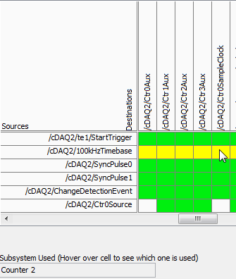
I don't know why this is, but if I start the PWM task first, and then the task of the encoder, it also works. I should also mention that initially I was using counter 0 encoder, which caused a shift in the 100kHzTimebase to Ctr0SampleClock, which, according to the ways of device 9411, is not supported. Yet it worked (in itself). I wonder if this is happening under the hood isn't quite what is shown.
What is exactly the conflict and what can do to avoid it? The reasons for having to use specific modes and the settings (for example, the 'continuous samples' with 100kHzTimebase clock) are rooted in various performance and requirements of optimization that were created in a previous version of our software, so I prefer not to take a completely different path, if some small changes would lead us to correct the problem.
I appreciate your help.
Kamen
Hi Kamen,
The time base of 100 kHz is not a direct route to the counter sample clocks, the device actually uses one of the other counters to complete the road (the routing table is a little misleading here because it shows 2 meter that one always doing road - in fact it will be any available counter):
So in your case, when you start the task of the encoder, it uses one of the other available counters to complete the configured road (100 kHz to ctr2 sample clock timebase). Of course, she chose meter 3.
Possible workarounds (looks like you have already found one yourself):
1 start the PWM before the task of the encoder task - if the task PWM starts first the counter is already booked and the task of the encoder would choose another available counter to complete its road.
2. explicitly reserve the PWM task before you begin the task of the encoder (if you need to start the task of the encoder first).
3. use cDAQ1/_freqout to generate the clock sample 100 kHz signal and use this instead of routing to the time base of 100 kHz to the counter sample clock.
Change autour counters should also work, but I'm not 100% sure how the unit selects which counter to use for routing (I don't expect change in the future, but if it's not explicitly spec'ed somewhere so I wouldn't take my chances)-if it were me, I would choose one of the other options above.
Best regards
-
Hello
I have a cRIO-9014 with a NI9505 DC brushed servo drive module and I would like to program the FPGA to PWM and encoder, quadrature, interfacing using the functions of intellectual property intellectual property mentioned in "CompactRIO Motor Control Basics Tutorial":
DX of encoder quadrature method (FPGA, using SCTL) .vi
Pulse Width Modulation (FPGA, using SCTL) .vi
I did a search at ni.com/ipnet but I could not find them.
Where can I find free downloadable IP cores for the blocks of PWM and encoder to include them in my interface FPGA program?
Thanking you in advance,
Manual
Found by myself (google search!) to:
https://lumen.NI.com/nicif/us/codepowelecguide/content.XHTML
-
USB-6008, how to calibrate two signals are equal entry?
HI all, I use NI USB-6008 and evaluation of labview 8.5, using the daq assistant.
1st quarter) to calibrate the two input voltage signals become equal?
Q2) I used the comparison for example function: not equal. When the two entries get value not equal, how to output of 0-5 v output?
If someone need more information to help me, I can provide.
Not sure at all what you mean by "0-5 v output to the output. Want you the difference between the two inputs to output?
In addition, two input signals will probably never equal. It's just not something that exists in the numbers floating point on a computer. You must subtract one from the other and uses in the range and force the function to determine if they are close enough.
-
I have a USB-6008, I read an entry on the OID.
I want this 1 report when the line has a present 5v and 0 for something else.
When I don't have anything on the lines. It reads 1
How configure it to read 0 when nothing is connected?
Also how I re this in c#
Thank you
Hello ashitakaLax,
The USB-6008 housing has an internal pull-up resistance to 5V (according to page 22 of the User Guide and specifications) that pulls the line to 5V when nothing is connected.
In order to change this, you can add an external resistance of menu drop down to make the output to the earth when it is disconnected, if your device should get power to fuel the high line.
Kind regards
-
cRIO - H bridge using the PWM output and input only encoder control
Hello
I am currently working on a project to control a 230V brushed servo motor using cRIO. The engine drives a linear step and the final project needs to create a control of position of the engine that the user is able to enter a speed, position and control steps to move to this position.
I use a bridge using NOR-9401 and H to power the motor circuit and a PWM output to move the engine. I also have an encoder, quadrature, connected to a NOR-9403 read position and speed. I use the example program of encoder for the NI 9505 - in my application.
There is no voltage or current on the drive circuit sensors so I wouldn't be able to have a closed loop current in this case. The scene release mechanism is such that the position is locked if the motor does not move and I do not need a torque control to keep the engine in place.
To achieve this, I just wouldn't be able to use a single PID VI (probably the FPGA VI express for discrete PID)?
I am not very well versed in the theory of control, and therefore no indication in the common sense would help me a lot.
Thank you very much!
Sexy,.
in general, it is best to use a cascade control loop structure but in principle must also be able to use the output of the control loop of position as an input to the PWM generator. The main disadvantage of this configuration is the current limitation missing. Without current meaning is no longer the only way to protect your engine from drawing too much current to limit to the current maximum output of your diet, or to limit the maximum duty cycle of PWM. Without current information, the last method is quite inaccurate, but better than nothing.
I agree with Mike, you should look in the examples of the 9505 module and use the controller position vi of these examples. This PID controller is optimized for motion control applications and it is implemented in the fixed point arithmetic, offering the best performance on and FPGA.
Kind regards
Jochen Klier
National Instruments
-
It worked fine on previous versions of Windows including Vista Ultimate. I'm now running Windows 7 Ultimate.
The correct URL is
This does not mean that the procedures above do not work, but I did the following:
- Download and run spring 2004 original TV Tuner Driver Collection (sp24012.exe)
- Open the Device Manager
- Uninstall the wrong drivers Conexant highlighted by the yellow triangle with exclamation point. Click on delete to remove the driver
- Disconnect from the internet
- In Device Manager, click Action > search the hardware changes (if you don't unplug Internet, a ToolTip is displayed informing you that drivers are updated from the internet. Click on the bubble, make right click in the window that opens, click on cancel the update)
- Follow the instructions to install the drivers from C:\hp\drivers\TVTuner
Windows Media Center should recognize your TV tuner.
Maybe you are looking for
-
C:\Users\Rext\AppData\Local\Temp\nsmail.tmp
Unable to find the temp dir, or if I do they are EMPTY! This was bugs me for some time, please help rex thompson
-
I installed and then uninstalled a program called classicshellsetup that converts win7 start xp features type of starting. I rebooted. Then my tools/downloads window that was busy was now empty. If I download a file it is OK, but the previous history
-
Compatibility with LabVIEW Windows 8
Windows 8 will come out in a week. I am looking to buy a new PC to run labview on and I can't find whether or not LV2011/LV2012 will run on Windows 8 or not. And nothing said about it yet?
-
Hi This is my first post here.I would like you to ak you a few questions. I have the WAG54GS router with this settings except that the LLC is not on VC. My problem is that E3000 support only PPPoE. This is not a problem because my provider also suppo
-
CQ60-615dx: Compaq Presario CQ60-615dx - how to reset the bios password?
I have an old Compaq CQ60and get the power on password. (58134685), anyone know if there is a jumper to clear the password.