Amplitude of the Signal after the FFT analysis
I'm currently trying to find the amplitude of a signal after running a FFT analysis. I use this for image analysis MTF. I take the profile of the line of fire (with an alternation of black and white bars) and convert it to a signal. This signal is then introduced to a FFT Mag/Phase VI extent and output of the FFT. My program then enter the amplitude to frequency of alternating black and white bars.
My problem is that the amplitude seems to be scaling by a factor. I would like to find the exact amplitude of the signal of my analysis. Anyone know the factor of scale or any problem with my program? I joined the program and the image that must be analyzed. Just browse to the image in the VI and run the program and you will see the MTF chart resulting.
Thank you
Ronak
Tags: NI Software
Similar Questions
-
The size of the FFT unexpectedly affecting maximum frequency
I was playing around with the Labview Signal Processing course manual exercises (NOR, 1997), when I came across the unexpected result. I have included below the block diagram for exercise 3.1 (one side FFT) of the manual. This demo vi had left the size of the FFT (by default). I don't know what is this default value. It is not stated in the context-sensitive help. I tried to add to the size of the FFT. Unfortunately the FFT analysis did not give a precise answer, when I put in the size of the FFT. For example, I set the frequency of the 100 s, Fs 300 Hz sinewave and non of the sine wave 500 samples. When the FFT size has been set to 256, I get 2 to 51 and 102 Hz frequency peaks. The size of the FFT of 512, I get a peak at 102 Hz. 1024 of the FFT size, I get a polymorphic waveform!
However when I put the size of the FFT-1 so I got the correct peak at 100 Hz. I guess that's the default size FFT. I could also get the correct TFF frequency, if I set the size of the FFT (500) to the same value with # no samples (500).
Is there anyway I could set the FFT size and still get the correct output of the FFT. Thank you.
This was recorded for 2011.
-
Hello
I have a sinusoidal signal that oscillates around zero the axis in the negitave and positive. It is to measure the height of the waves on the static water level in a wave tank. I am calculating the FFT but the amplitude is less than the height of the waves in the time domain. Does this mean that I'm the wrong calculation? I don't know wheather I should use the FFT Peak or RMS? I assumed that the amplitude of the FFT should give me the same amplitude as the time domain.
Any advice would be greatly appreciated.
Thank you
Donners,
It can get complicated, but I suspect that what you see is the result of the frequency of the waves is not not exactly at the frequency of the FFT bins. For example, suppose that df = 1 Hz. Then each element of the array FFT represents the energy in a "sandbox" a hertz wide centred on the frequencies of the integer. For a wave with most of his energy to 7.3 Hz TFF likely values not null for trays Hz 7 and 8. In real systems with noise and light frequency variations, it is not uncomon for data can be spread over 10 or 20 locations. To get the fundamental signal amplitude, you would need to combine the energy in all stores. Since the FFT produces complex output, the phase component must also be considered. Non-sinusoidal Waveshapes means that part of the energy is in harmonics. A pulse square can have a large enough amplitude, but there's still no broad spectral components.
The short answer is that generally there is no easy way to get a precise correlation between the amplitude of crete in the time domain and the amplitude of spectral components in the field of the freqeuency.
Lynn
-
find the highest amplitude of a signal
I have to find the value of the highest amplitude of my signal. This should be done automatically without using cursors
What is the data type of your signal (Dynamics, wave form, table, etc.).
For example, try:
-
The monitor loses signal after some time
During the installation of windows vista, the monitor would lose the signal after some time (the screen turns black and does not) while the computer is still on. I am currently using ATI radeon hd 5750 and I tried to connect two monitors to the video card and it wouldn't work (both monitors loser of the signal)
Hi PaulYea,
1. what type of Installation are you trying? It's an upgrade or clean Installtion?
2. what happens when you connect to the system now?
If you attempt an upgrade installation, then try the update the video card drivers and check:
Update drivers: recommended links
http://Windows.Microsoft.com/en-us/Windows-Vista/update-drivers-recommended-links
You can also check out the link to the manufacturer to download the drivers:
You can also try running Upgrade Advisor and start the upgrade installation
Check out the link:
http://Windows.Microsoft.com/en-us/Windows/downloads/Upgrade-Advisor
Note: This also applies to Vista.
For more information, see the link:
Solving Windows installation problems
http://Windows.Microsoft.com/en-us/Windows-Vista/troubleshoot-Windows-installation-problems
Hope this information is useful.
-
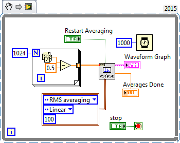
What does not restart in the FFT functions way?
Hi all
I would like to know what that "restart average" made for the FFT functions. According to aid,"reboot on average indicates if the VI restarts the process chosen medium." If restart on average is set to TRUE, the restart of the VI the selected with an average of process. If reboot on average is set to FALSE, the VI does not restart the process chosen sprawl. The default value is FALSE. When you call this VI for the first time, the averaging process restarts automatically. A typical case when you need to reboot on average is when a major change of entry occurs in the middle of the averaging process"
I realized that the FFT function takes in an array of values and perform the FFT on it. If the FFT function keep a buffer previous values and clears when restart average = true? Because the FFT functions are not Point by point and they take both in all the data to deal with, "a major change of entry occurs in the middle of the averaging process" can be true?
Thank you!
Sigh. I really tried to explain what was going on (probably) with this function, you use (and, I thought naively, you understand), but you got me wrong.
This VI creates a zero average noise signal, providing 1024 points per second. Do you know what should be the power spectrum of the signal? Due to the randomness of the input signal, the power (for a small finished sample) spectrum will also have a random component. If you had several ghosts of power on average, the average would begin to converge with the expected for random noise power spectrum.
If you run this VI and look at the Spectra resulting (on average), you will notice that the first spectrum is the most "spice" and that spectra are averaged, the variation is reduced and diminishes the value of crete (shown by looking at the scale of Amplitude). At any time, you can press "Reset average" and see this... reset the average, the following spectrum shows the growing nose, etc.
It shows the right way to test the function of the power spectrum and discover what he does. My suggestion as to what makes this function seems to be largely correct.
Bob Schor
-
How to find the ratio between the two frequencies in the fft
Hi, I'm Jean,
I need to find the ratio of the frequencies of 1st and 2nd graph fft.
Already, I received information of this site only. Mr. Alten helped me.
Now, I have to continue the same problem and need to find the ratio of the frequencies.
Please someone help me guys...
I will attach my vi file and the text file.
John,
Should you report the frequencies or the report of the amplitudes of the components at these frequencies?
The Information.vi of your multiple for the Signal Processing, extract > range of measures of waveform should do what you want.
The frequency resolution is not very good because you have cycles relatively little waveforms (2 ~ for the lower frequency). I added a few zeros to improve resolution, even if a larger sample of data would be better.
Lynn
-
The amplitude of the frequency. Bode CD. State space
Hi all
Gently, I have a simple model that gives me a Bode phase and magnitude, using the block 'CD Bode'. AFAIK, this block takes the representation of the State space and assesses the frequency and scale of the system.
Can I change the value of the Phase or amplitude Bode? by means change the input signal that bode uses to evaluate the response of the State space?
Note: The entry, I want to say here is the value of the sinusoidal signal that Bode uses to give the phase and the amplitude of the State space.
Thank you
The works of Bode CD functions as a "sweep" of all frequencies and who you are. The algorithm is not a frequency controlled, he comes back the entire spectrum. You can't just get a specific frequency. However, if you use the fuction 'Assess frequency of CD', you can provide the model and frequency, and this will give you the specific Mag/Phase for this frequency. This example shows how to do this in LabVIEW:
C:\Program Files (x 86) \National Instruments\LabVIEW 2014\examples\Control and Simulation\Control Design\Time Analysis\CDEx Lin Simulation and stable State.vi
Now, if you want to 'form' your frequency, so you can create another model, connect with each other and try to change the output frequency. This example shows how to do this:
C:\Program Files (x 86) \National Instruments\LabVIEW 2014\examples\Control and Simulation\Control Design\Frequency Analysis\CDEx frequency analysis
If you just want to "simulate" the response of the signal to a specific sine wave, then you will need to you another function in the time domain palette called "linear Simulation CD. With this, you can generate a specific sine wave and you can see his behavior in the time domain. Here is an example:
C:\Program Files (x 86) \National Instruments\LabVIEW 2014\examples\Control and Simulation\Control Design\Time Analysis\CDEx sine wave with Mathscript.vi
Hope this helps,
-
How we increase the y-axis (amplitude) of the audio tracks?
How we increase the y-axis (amplitude) of the audio tracks? My patient seems to have flatlined. I don't want to increase the gain, just the way the waveform looks like on my monitor.
DrDtMM
'Expert opinion' is a part of the new interface of first elements 11. In version 10, you have the timeline and stage line discovers the choice.
For now, I will assume that you are in the view of the timeline where you use the video and audio tracks and not a strip of film with slots of the scene.
I suspect you may be after the following. Let's wait and see.
To the right of the where it shows the "Audio 1" name is a microphone icon. Representing the 'Audio display Style. There are two Audio display Styles and you can select either by activating / deactivating the microphone icon.
a. in a case, you will see the waveform, plus an orange horizontal line which is in general the rubberband of Volume for Volume set. This display Style has a light green background.
and
b. otherwise, you will see a dark horizontal line, any waveform. This dark line is on a light green background.
I suspect that you are in 'b '. Are you aware that 'a' exists.
If you want a version really blown upward from 'a' to watch, you could separate the audio from the video, double-click the audio signal in order to open the preview windows and adjust to the top of the preview window.
We will follow your follow-up to the top see if we get in sync.
Thank you.
RTA
-
How to configure the amplitude on the CLK OUT coming of the NI PXI-6652?
In the document specification NI PXI-6652, it clearly says under CLK features OUT of this magnitude ", Software Configurable. But I couldn't figure out where I can do? I'm going to CLkOUT 1Vp - p. I want to program to 2.5 VDC.
Ashok
Hi Solanki-
The amplitude of the CLKOUT signal is selectable by software between two levels. Under a 50 ohm load, you can change the amplitude of 1 p to 2.5 V p Pei Pei V using a niSync property node. This can be found in LabVIEW under the palette of NOR-SYNC. Place the property node down and click on the word "Property". Select Properties Clk» Clk Out Gain Enable. Then right-click on the property node, and then select "Change while writing." Then right-click on the entrance to the property and select Create' constant. The constant change True and your CLKOUT will be high.
I hope this helps. Good luck with your application!
-
frequency of the FFT is not compatible with matlab
Hi all
Please find .jpg in the attachment. The signal is generated by a signal generator and collected by datashuttle/3000. Then I use the "FFT module" and "statistical value" to find the position max (frequency). I also downloaded the data and processed by matlab FFT function. What I find, is that the value of the frequency of dasylab is always slightly less than matlab. For example, when the signal generator gives 10 Hz, the dasylab indicate 9,77 Hz and matlab gives 9.99 Hz I used matlab for years, so I have confidence in it. There must be something wrong with my program or dasylab. First I have is because of the resolution, so I changed the "statistical values - mode - based block and tick (not quite sure about this) parent block and a value for every 240 blocks, which is also for the sampling of matlab." Unfortunately, there is no change at all. Can anyone help?
Thank you very much
Alan
What is your size of rate and sample block DASYLab?
Try to make the block size an even number, for example, if you sample at 1000 Hz, made the size of the block 500 or 1000.
What is the equivalent block Matlab? The amount of data is used for the calculations.
You can also use the module block average average more than 250 blocks and then use the module of statistical values to calculate the maximum Position.
-
Amplitude of the reading of the oscilloscope
Hi Im tring to towing to read signals of an oscilloscope to different frequencies and Amplitude/Frequensy tables for each of the signals. but in my program, I have tow problems.
1. during playback of the oscilloscope and the entry in the text file I get the whole array af graf i.e. (Amp/hour), but I only need the value of peak to peak amplitude not the entire table (not the entire table).
2. I can't read the chanel signal 2.
Thanks for your help
Thanks for your quick response
1. it is a function in labview to return the peak-to-peak of the measured value, may you enter it.
2. not the trace of the second is not visible in the scope.
You are right, I well recognized that there are som parties unnecessary in the loop but I knew not exactly the parts that I could break out of the loop.
-
Why the FFT spectrum gives values of RMS?
Dear Sir
I want to get the value of crete to crete on FFT spectrum. But he gives values of RMS. Can you please guide me how can we peak to peak on the FFT spectrum. Attach the vi is for example.
Kind regards
Urfee
Tronoh wrote:
Dear Sir
I want to get the value of crete to crete on FFT spectrum. But he gives values of RMS. Can you please guide me how can we peak to peak on the FFT spectrum. Attach the vi is for example.
Kind regards
Urfee
What does it mean to get the value of Ridge Crest of a FFT spectrum? [I understand getting the value of P - P of the signal ...]. Note that the parameters on the average you attached (which shows mean quadratic value, by the way) refers to the way in which the Spectra will be averagedand RMS is logical (logical) in many cases, but I'm at a loss to understand the average peak-to-peak here...
BS
-
MacBook Air, OSX 10.10.3, 128 GB; 2 TB Time Capsule ME177LL/A.
Final objective: use Time Capsule as a Time Machine for my MacBook Air and as a storage solution for large files that I don't want permanently on my MacBook Air.
So far, I've implemented the TC and set up Time Machine on the TC. I was able to create 2 partitions on the TC using disk utility then that TM was a backup and the disk was recognizable in disk utility.
Under Finder/shared, I see the TimeCapsule 'airport', and when I click on it it is a file called "Data". I was expecting to see my two partitions here. Under 'Features' is a ' Zissou31 MacBook Air (3)"sparsebundle file and I can also create folders here and drag and drop files on the TC here. I can see the partitions in disk utility, but how do I see/use the partitions I created in the Finder?
I fear that this may not be set up correctly and I'm either losing on an entire partition I created or these files dragged/dropped may be at risk of overwriting of TimeMachine. How can I make sure that the file analysis is on the appropriate partition?
I disabled TimeMachine and go back to see if I could 'point' to one of the partitions, but the "Data" folder is the only thing that TimeMachine seen. How do I point time Machine for one of the partitions?
Thank you!
In addition, in disk utility, I can see one of the partitions TC is related to the time Machine, indicated by the icon Time Machine green bottom left, but two partitions seem to fall under "Zissou31 of the MacBook Air (3) .sparsebundle.
-
Hello world
I have copared the original FFT for LabVIEW and MathScript algorithm execution.
To do this, I calculated a 128 k TFF 100 times. The necessary calculation by MathScript time
is 4 - 5 times higher. I used a very simple MathScript code that calculates just the FFT,
No loops, etc. that were involved. Anyone know a good reason for this? It cannot be explained
through the exchange of data between LabView and MathScript. MathScript uses a less efficient
FFT algorith that LabView?
Thank you
Ulf
Maybe you are looking for
-
no game i AppStore. Where can I download minecraft? for my son.
-
Satellite A300-1MC and autonomy
Hi all I've had my new laptop for 2 months now and overall I am satisfied, only 2 points of clarification I need help is the following: (1) when I charge the battery completely and then click the icon in the lower right of that remaining battery life
-
HP 240 G4: Drivers for HP 240 g4 - wifi problem not connect properly
Hi all We are a group of students at a University in the Argentina. We get HP nootebooks to make a lab. But we have a big problem with the weak WIFI signal. We found a post were the problem is resolved the with the same model: HP 240 G4: http://h3043
-
Vista Home Premium Device Manager empty
After plugging in a USB stick for laptop my wife and successfully copying data to the hard disk, I noticed that there is no icon to the icon 'Remove hardware safely' in the system tray. I checked under the taskbar properties to make sure that the ic
-
Permissions applications - storm
Hi, I'm testing the Application API permissions (make the audio recording...) but have not found a way to make it work in the Simulator. I tried with the JDE and the Eclipse plugin, which allows the code signature API and the ApplicationPermissionsDe