Amplitude of the reading of the oscilloscope
Hi Im tring to towing to read signals of an oscilloscope to different frequencies and Amplitude/Frequensy tables for each of the signals. but in my program, I have tow problems.
1. during playback of the oscilloscope and the entry in the text file I get the whole array af graf i.e. (Amp/hour), but I only need the value of peak to peak amplitude not the entire table (not the entire table).
2. I can't read the chanel signal 2.
Thanks for your help
Thanks for your quick response
1. it is a function in labview to return the peak-to-peak of the measured value, may you enter it.
2. not the trace of the second is not visible in the scope.
You are right, I well recognized that there are som parties unnecessary in the loop but I knew not exactly the parts that I could break out of the loop.
Tags: NI Software
Similar Questions
-
reading of multiple channels on the oscilloscope
Hey there everyone,
First of all, thank you for taking the time to read this. I'm still relatively new to LabVIEW, but I read most of the bases.
How is this issue work VISA.
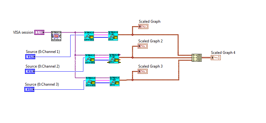
I have an oscilloscope which has sensors to 3 channels and I want to display 3 channels on the same graph. The example of VI, which is included with the driver allows me to access a channel however it also adds other features, such as the control device that I didn't need, I just want to read data from the oscilloscope.
I will not be able to access the gear for a few days, but have started coding. Here's what I've coded so far.
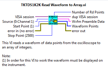
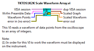
The first blue function is 'Reading of Array wave' and the second 'wave in table scale ".
Am I allowed to access the VISA like this? Or is it illegal access that would cause problems?
I tried to access several channels before, so I was in the laboratory, however they have always produced errors.
I use an oscilloscope tektronix TDS2013C, Labview 2013 and that you have downloaded the driver concerned for my model.
All relative links to learning tools or help would be greatly appreciated!
-Nam
Please read the manual on a reading and extraction.
As I said, the reading will launch a new capture. When you call it 3 times, each record returned will be later time than the previous capture. Either do what I said or call an extraction 3 times now.
-
acquire data from the oscilloscope DPO2024
I am trying to acquire data from the oscilloscope DPO2024 using labview. I am able to do, but my vi file only works for channel 1. Other than channel 1, it does not work and instead, it changes the adjustment of the oscilloscope as well. Find the vi files attached.
Any help is very appreciated.
You must connect the channel in the waveform of reading. It is default to channel 1 if thread continues.
-
How to configure the amplitude on the CLK OUT coming of the NI PXI-6652?
In the document specification NI PXI-6652, it clearly says under CLK features OUT of this magnitude ", Software Configurable. But I couldn't figure out where I can do? I'm going to CLkOUT 1Vp - p. I want to program to 2.5 VDC.
Ashok
Hi Solanki-
The amplitude of the CLKOUT signal is selectable by software between two levels. Under a 50 ohm load, you can change the amplitude of 1 p to 2.5 V p Pei Pei V using a niSync property node. This can be found in LabVIEW under the palette of NOR-SYNC. Place the property node down and click on the word "Property". Select Properties Clk» Clk Out Gain Enable. Then right-click on the property node, and then select "Change while writing." Then right-click on the entrance to the property and select Create' constant. The constant change True and your CLKOUT will be high.
I hope this helps. Good luck with your application!
-
How to set the vertical position of the oscilloscope (Simulation)
Hey guys...
I think do a very basic oscilloscope in labview (simulation only).
So I'll show 2-4 channels to the oscilloscope. For this I will use a waveform graph and show the parcels of 2-4 in the same graph.
But how to define the vertical position of the individual parcels (channels) for comparison?
Suggest an idea please...
Make additional changes the values in your table do you do whatever will be will be incorrect. For the offset adjustment, assign each parcel at a different scale y and set the minimum and maximum of the scale up and down the waveform.
-
With an average of readings of the oscilloscope
I have a virtual four-channel oscilloscope. I have spark and get values in a 2D array. I would like to the average of the five consequetive results. However, the program, I am changing is badly coded, I can't use shift registers. My only option is to store the values of the oscilloscope somewhere and after getting five of them by dividing by five.
I tried with tables, but I have no havw a lot of experience, so I couldn't do. What would be the best approach?
Thank you
Erden
Hi Erden,
a local variable is rarely the right approach
 (you know LabVIEW uses a DATA flow approach?)
Try this instead:

Two ways, with or without change of register...
-
The amplitude of the frequency. Bode CD. State space
Hi all
Gently, I have a simple model that gives me a Bode phase and magnitude, using the block 'CD Bode'. AFAIK, this block takes the representation of the State space and assesses the frequency and scale of the system.
Can I change the value of the Phase or amplitude Bode? by means change the input signal that bode uses to evaluate the response of the State space?
Note: The entry, I want to say here is the value of the sinusoidal signal that Bode uses to give the phase and the amplitude of the State space.
Thank you
The works of Bode CD functions as a "sweep" of all frequencies and who you are. The algorithm is not a frequency controlled, he comes back the entire spectrum. You can't just get a specific frequency. However, if you use the fuction 'Assess frequency of CD', you can provide the model and frequency, and this will give you the specific Mag/Phase for this frequency. This example shows how to do this in LabVIEW:
C:\Program Files (x 86) \National Instruments\LabVIEW 2014\examples\Control and Simulation\Control Design\Time Analysis\CDEx Lin Simulation and stable State.vi
Now, if you want to 'form' your frequency, so you can create another model, connect with each other and try to change the output frequency. This example shows how to do this:
C:\Program Files (x 86) \National Instruments\LabVIEW 2014\examples\Control and Simulation\Control Design\Frequency Analysis\CDEx frequency analysis
If you just want to "simulate" the response of the signal to a specific sine wave, then you will need to you another function in the time domain palette called "linear Simulation CD. With this, you can generate a specific sine wave and you can see his behavior in the time domain. Here is an example:
C:\Program Files (x 86) \National Instruments\LabVIEW 2014\examples\Control and Simulation\Control Design\Time Analysis\CDEx sine wave with Mathscript.vi
Hope this helps,
-
are there different scales of two waveforms of the oscilloscope
Hello
I am writing two waveform on the oscilloscope. But one of the wave are very small scale.
Y at - it any wave of scale are two on the graphical indicator of waveform so that the small signal can have higer resolustion?
Thank you!
Hi tian.
Seek the help of LabVIEW for 'scale double y"...
-
Amplitude of the Signal after the FFT analysis
I'm currently trying to find the amplitude of a signal after running a FFT analysis. I use this for image analysis MTF. I take the profile of the line of fire (with an alternation of black and white bars) and convert it to a signal. This signal is then introduced to a FFT Mag/Phase VI extent and output of the FFT. My program then enter the amplitude to frequency of alternating black and white bars.
My problem is that the amplitude seems to be scaling by a factor. I would like to find the exact amplitude of the signal of my analysis. Anyone know the factor of scale or any problem with my program? I joined the program and the image that must be analyzed. Just browse to the image in the VI and run the program and you will see the MTF chart resulting.
Thank you
Ronak
-
How we increase the y-axis (amplitude) of the audio tracks?
How we increase the y-axis (amplitude) of the audio tracks? My patient seems to have flatlined. I don't want to increase the gain, just the way the waveform looks like on my monitor.
DrDtMM
'Expert opinion' is a part of the new interface of first elements 11. In version 10, you have the timeline and stage line discovers the choice.
For now, I will assume that you are in the view of the timeline where you use the video and audio tracks and not a strip of film with slots of the scene.
I suspect you may be after the following. Let's wait and see.
To the right of the where it shows the "Audio 1" name is a microphone icon. Representing the 'Audio display Style. There are two Audio display Styles and you can select either by activating / deactivating the microphone icon.
a. in a case, you will see the waveform, plus an orange horizontal line which is in general the rubberband of Volume for Volume set. This display Style has a light green background.
and
b. otherwise, you will see a dark horizontal line, any waveform. This dark line is on a light green background.
I suspect that you are in 'b '. Are you aware that 'a' exists.
If you want a version really blown upward from 'a' to watch, you could separate the audio from the video, double-click the audio signal in order to open the preview windows and adjust to the top of the preview window.
We will follow your follow-up to the top see if we get in sync.
Thank you.
RTA
-
Generator functions agilent modulated the amplitude of the voltage so that the signal
Hello
I'm new on the Labview.
I need to provide a series of tensions with increases step on my device and it repeats again and again.
For example, (5V 0V to 10V 0V 0V 15V) * 5 times
In the past, I turned down on the generator Panel of Agilent 33220 functions by myself.
It's stupid, so I will try to use the Labview to do the same.
I have download the Agilent 33220 Vi function generator has and write a loop for to do this. It can work.
But I found a problem. Each change of amplitude voltage, generator Agilent 33220 A functions will cease to exit and then output the new value.
Because this short period of no output voltage, the dynamic behavior of my device will be destroyed.
How can I do?
You made a classic mistake. You have placed the Initialize and close inside the loop. The Initialize will, by default, perform a reset feature, which disables the output. Initialize outside a loop, do your stuff inside and close the loop.
Regarding your code: I strongly recommend looking at the model of ramp function. It seems you want to increase the parameters of voltage to zero between the two. This can be easily done by creating your rising tensions ramp and then creating another matrix of the same size zeros and interlacing then the two tables. This will give you a complete range of voltage values, without to need two loops and determine what step you are on, etc. etc. For example, the following code will give you 5, 0, 0, 10, 15, 0 sequence fairly cleanly:

In addition, never perform a comparison of equality on the floats. If not, you owe me nickel one another in my retirement fund.
-
How to design the oscilloscope... need idea, advice and suggestions...

Hello...
Student MI... so I'm new to LabVIEW... so I use LabVIEW 8.6 and NEITHER cDAQ-9178 for the connection between the material... and my PC... now, I have final project... I have to design digital oscilloscope using labview, but I have several problem...
1) How to design the scope of design
(2) I have the simple design pattern to display the wave... but stil have some problem, this block diagram... how I want to develop the other party such basis of design time, control vertecal, cityscape control, capture the wave... and etc.., I was the previous oscilloscope in labview reserch and I desgin again by reffer the previous... but still no function...
Hopefully, someone can help me... to give me an idea, opinion or suggestion for me to complete my project... fnl plz... now, I declare my design... and all I recommend and agree with the suggestion of someone... Thank you very much
Hello
That must be validated in the jury of LabVIEW so I'll move it for you. The jury of feedback is used specifically to provide feedback on the forums and their features.
In order to receive the best support on the Forums of Discussion OR, please post your question publicly on the map that best matches the products you use. This allows your question be seen by members of the forum in the world, thus allowing users the most expertise in this field for you help. Additionally, once your issue is resolved, users of the forum with the same question in the future can benefit from your experience.
To start a new thread on the Forums OR, go to the correct product management on forums.ni.com Board and click on the "New Message" button. You will be directed through a search to see possible solutions. If you don't find a solution, you can proceed to post your question on this Board.
Kind regards
Jordan
The Forum Moderator OR -
Problem during connection of the oscilloscope
Hi Im writing a program for measring a signal to oscilloscope Tektronix TDS3054B
The Instrument Driver Network has links that explain what a LabVIEW driver is and how to use a. Then click on the previous link I gave you and download the appropriate driver. I would recommend the project-style driver.
-
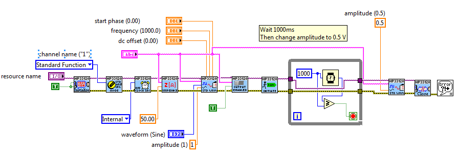
Change the amplitude of the Agilent function generator output while the output is on
Hello
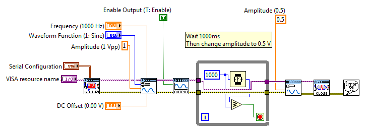
I am writing a program to scan the amplitude of a sine wave of a function (Agilent 33210 a) generator output. I have two sets of pilot example: Agilent 33xxx and HP33120a (the first one uses VISA, IVI 2 uses).
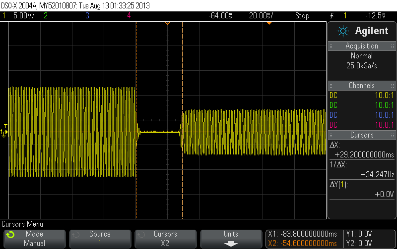
Using the example of driver code, I changed to generate a sine wave to 1Vpp, wait 1 sec, and then modify the amplitude of 0, 5V. I have attached the images in my field that show what happens when I do that. The two examples cut first exit before Relighting with a different amplitude. 33xxx driver takes 140ms for change, and has a strange burst between the two signal. HP3120a driver takes 30ms and cleaner air.
Agilent 33xxx example using:
\
HP33120a example using:
I would like to have the change is instantaneous. When you use the generator manually, I can turn the button and change the output in real-time without delays.
Thanks for the suggestion of Mateus, but I am trying to automate this process of my best. Change the VISA pilot is the direction I want to go.
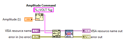
Thank you crossrulz... I wrote a new issue VI of the Standard waveform VI set up so that it simply writes the new amplitude control and none of the other things. Worked like a charm! Now the waveform changes amplitude without turning off the exit. I also checked to see if re-defining the shape of sine wave (even if the original is also sinusoidal) was the cause of the delay as you suggested, and you were right. Thanks for the help!
-
amplitude of the waveform graph
Hi guys,.
could you please tell me how to control the amplitude of a waveform graph. I want the mV amplitude, and I want to control the scale of numbers also.
Thank you
Bill David
Bill David,
You want to manually set all by developing the program or by running program?
For a manual start by turning off Autoscaling on axis Y. Then comes the value end upper and lower values you want.
Programmatically is similar except that you use property nodes. Some properties have names that might be a little confusing, you may need to do some exploration and trial. Context-sensitive help and help detailed will be your friends.
Lynn
Maybe you are looking for
-
How to get google work once again, I tried all of the suggestions I've seen so far!
The service Google has suddenly stopped working in Firefox. In the box of the home page, of toolbar and to address, when I search I just get a blank screen, no results. I uninstalled Firefox and reinstalled from a new download. I checked all add ons
-
I need to post a tutorial for some training company corporate site only supports Microsoft Windows. I'll buy a MacBook in the coming weeks when I go to training and I wonder if there is a way to load windows on an external drive and launch it on my
-
I want to use a USB device to connect to the Internet, as my ethernet card is US I can not configure the Ralink dongle and I am referred to in article 871122 on the Microsoft site to activate zero wireless connections. How to do this please? USB to
-
Yesterday, I lost my sound and seem to get only beeps. Have not changed anything and checked all connections and the control panel. How to restore the sound, please? Thank you.
-
battery is not detected, plugged in and not charging
Hello I have problems with charging the battery and my Windows 7. When starting, the battery is detected in the BIOS and load (led lit without flashing). As soon as the computer stops on my drive HARD and Windows loads, the light starts flashing, ind