amplitude of the waveform graph
Hi guys,.
could you please tell me how to control the amplitude of a waveform graph. I want the mV amplitude, and I want to control the scale of numbers also.
Thank you
Bill David
Bill David,
You want to manually set all by developing the program or by running program?
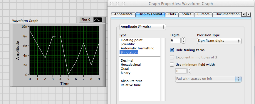
For a manual start by turning off Autoscaling on axis Y. Then comes the value end upper and lower values you want.
Programmatically is similar except that you use property nodes. Some properties have names that might be a little confusing, you may need to do some exploration and trial. Context-sensitive help and help detailed will be your friends.
Lynn
Tags: NI Software
Similar Questions
-
missing samples in the waveform graph
Hello world
When processing a file .wav into pieces, I noticed that there are missing samples on the waveform graph where two pieces must be met for the display. What could be the cause of this? Any help appreciated. Thank you!
Milan
Your method of reading in pieces in a for loop is create a table 1 d of waveforms with the tunnels of automatic indexation. It is as well as what you have the data appear in different plots. I don't know if that's what you want.
But if this is the case, the problem is that you get to the last point of the first plot, and the first point of the next parcel is a different value. Because they are two different plots that you do not get the line to join them, as you do between points that are part of the same plot.
-
How can I display only a part of the scale in the waveform graph
This is the first time I try to use the waveform graph, since now, I used the table of waveform.
The reason why I moved to the chart, it's that I need cursors.I have 2 problem
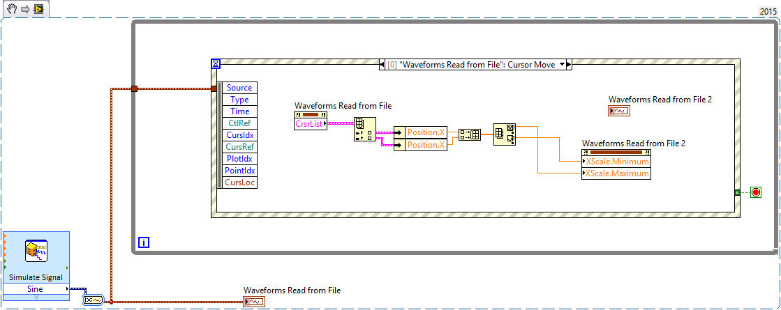
the first: in the diagram, the graph moves when I add a new data and the scale of the x-axis stay the same size, in the right size I always saw the new data. How can I do that with waveform graph?
Second: How do I say Labview to the day I click on the graph, I need that because when move graphic I lose the day, and to make I need to zoom out, I drag the imprecateurs.
All this must be done programmatically. The LabVIEW graphic accepts tabular data, not only as the table and the graph doesn't have the ability to retain the previous points, like the story of a graph. You will need to retain previous values and then continually update the graph with the old and new values to get a shift register "chart as behavior. Cursors should be written programmatically re of each iteration, since you rewrite the entire graph.
-
Change the axis label w.r.t. the scale automatically in the waveform graph
Hello
Is it possible to change category axis labels and the value the axis according to the scale automatically? I have a waveform graph which is automatically resized and values on the y-axis of milli, micro and nano volts according to the results of the output from the tests carried out. I need the label of the axis to change automatically according to the scale... Could someone tell me please how to do this. Thanks in advance.
Best regards
Julien
Alain,
I don't know exactly what you want.
If you want to just scale to change as follows: 10n or 5u, use the property format scale IF the Notation.
If you want to change the name of scale label text, you use the YScale.NameLbl.Text property. The attached VI shows one way to do something like that.
Lynn
-
Average value of the waveform graph
Hello everyone.
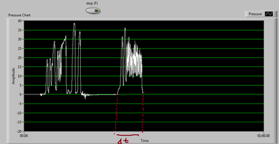
Can I do an interval of time, where I can measure the average value of a waveform graph?
for example the fom 0:30-0:45
I have uploadet my VI
:Thanks in advance
Orlando
-
How to synchronize the start time in the waveform graph
Hi all
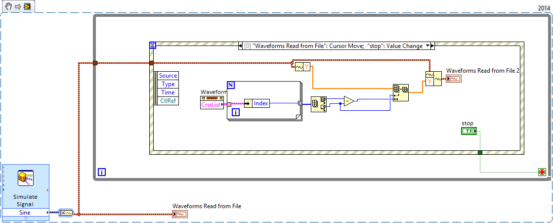
I just find a solution in the forum to select the data you want in a grap of waveform with cursors, however, I don't know how to synchronize the time of beginning of waveform for the second graph. How can I extract start time of the waveform with the index data?
Something like that? It is a bit gross, but is what I think you're asking, should be able to use it as a starting point.
The Max - Min is to make sure that the cursor is always valid.
-
Field of table to the waveform graph
Hi, I have a table I want it draw in a waveform graph. I tried to experiment with the wave function of building and others, but could not get anything out of it. And how to choose which points I would like to draw on the graph?
Thanks in advance.
You have only wired 2 signals, so just the two signals. If you need more, expand the node for merger signals and cable signals more to it.
5 and 6 are the numbers in column for Poly_M_Tem & TF_M_Temp, I had to delete the first column, as was the timestamps, and it was not necessary. It is so different from your 6 & 7.
Hope that makes sense.
-
you use an image behind the waveform graph?
Well guys, I want to know if its possible in LabVIEW.
I know I can put an image predefined waveform graph so still when I run my program I see that image.
But now I want to use a picture inside the graphical waveform... like a logo or something related.
Is it possible? If so, how can I do that?
Thank you
How about you, making the transparent graphic background and put the image you want behind it?
-
adjust the scale of the waveform graph
Hello
I have a graphic wavefrom receives two signals, can I adjust the scale of the y-axis of a signal?
Yes. You create a scale is double and set the plot of the new scale.
-
I have a chart single 2D out a conditional of a loop indexing output such that over the rows of the table are not the same size. -Basically, they have different starting and ending points and sizes. -Not so concerned by the endpoints, because as soon as I get correctly starting points, everything shows fall in place.
The challenge is that when I try to have the variable t0 (start time) for each line, the wave of construction vi form would always keep each line at the same starting point.
I used the approach bundled with success (the cluster approach ensures that each waveform starts at different times according to the guidelines of my t0 defined for each line) but then I'm not able to get in the channel names I could make using the graphical approach (wave generation) waveform.
In essence what I get here, I'm losing here.
Because I don't want one of my mentors, Bob and Altenbach have fed up with me I have attached a vi this time

Attached VI shows a combination of the two attempts (first with the waveform graph) and then with the graph of cluster
1. with the first (graphical waveform), I get my channel names as you wish, but the alignment of the wave is not correct.
2. with the second (graphical cluster), the alignment is good, but I can't do the names of channel in the chart, even if they are present in the cluster.
I read some reviews that mentions that attributes can be displayed with waveform and data Dynamics (not clsuters) so I guess that's why.
I saw another report indicating the start time for a waveform 1 d will always remain the same for the rest lines defined for the first line even if changed for the following lines in a loop.
So I guess my question is: what is the way around questions like that?
First of all, let me be the first to the congratulate and thank you for finally posting a code! I'm not 100% certain I understand your question or your code, but I have an idea, perhaps, of what you want to do, so I wrote a little VI who made something simple that could be relevant.
You mention waveforms of different lengths and beginning at different times. You also want everyone to have a unique attribute (although I'm not sure what you want to do with the attribute). So, I did the following:
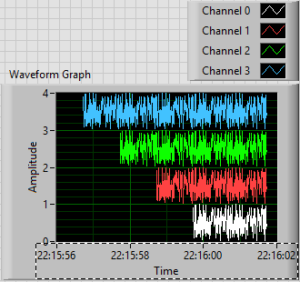
- Generated an array of 100-sample random to represent one second of a waveform.
- Created 4 waveforms on this 100-sample basis. The first waveform (channel 0) is just these 100 points. The second, 1 channel, is the concatenation of string 0 with the base of 100 samples, or a waveform "double". Channel 2 is 1 string concatenated with the base, and channel 3 is 2 string concatenated with the base.
- In order to trace the four channels that they rest 'on' the other, the waveform has the number of the channel added to it. Channel 3 is 3 + (4 copies of the basis of 100 points), a waveform 400-point random centered around a shift of 3.
- All channels have dt value 0.01 (but I guess I could have varied, as well).
- To make the channels start at different times, I started channel N N seconds before channel 0 (by subtracting the index of the loop, I, T0).
- For each channel, I created an attribute called "Chan" equal to "Channel N" (where N = 0, 1, 2 or 3, as the case may be).
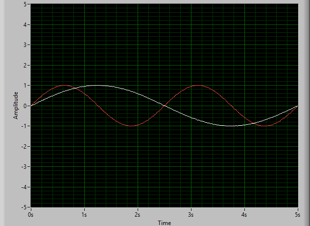
This is the plot that results. Scale X is the absolute time value (no Date) using the 24-hour HH: mm
 S format. You can see that the plots are 1, 2, 3 and 4 seconds of time, and are offset from each other by a second. I used the trace attributes to change the name to the respective attribute.
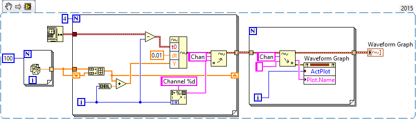
The code to do this is very simple - I almost don't need to show it, because I think it is completely described by the text above, but this is here:
Now, it was not that much faster that some of your previous posts, when you refused to your postcode, "guess us" what you wanted (but not to not correctly guess), you tried to "push" us in the right direction (still refuses to post code), and no one seemed very happy?
Bob Schor
-
Hello
I use the metal theme to design a façade of Labview. I would like to plot x, y of the data on a chart, however, there is only a graphic of waveform and waveform Graph available in the metallic theme. Can you help me in tracing the x, the data is in the curve of waveform in the attached VI?
Thank you
hiNi.
You can customize the graph of the metallic wave and replace it with a XY Chart and set some properties to match the waveform graph
Or let me do it for you
Joint back-saved for 2011
Cross posted at the "Discussion of UI military theme" on the side of the community
-
Hello
I have a question about the waveform graph. My prolbem is that the x-axis of graphic waveform shows only up to x = 0.1 and it does not show the chart more than that, and when I increase the X-AXIS scale in his PROPERTIS (lets say at x = 2), increase the Max on the x-axis (x = 2) but the chart presented to the 0.1! I have attached a very simple code that shows my problem.
Could you help me please? I need the graphics to show me for all values x, x = 0 to x = 10.5.
Thank you
Soran
Hi Soran,
Sorry, your question is still not clear to me.
You hear all the values up to 10? I kept freq = 0.1 and adjusted other values, don't know if that's what you are pregnant.
-
Multiple waveform graph, history of waveform card
Hello to all my colleagues.
I have problem with software of my purchase. I create software for the acquisition of 40 signals. I need to view and save these signals. I measure these signals with different frequencies (this depends on the user's selection), but the lowest frequency is 500 Hz and the highest is 2 000 Hz. Because I see a different size of X scale (5 sec - 60 dry), I decimate these signals for display and display only 100 samples per second.
I think that my problem is related to a very long history of waveform graph. When I display all signals in a single diagram, permanently signals are not displayed and the table is larger than the correct size of X-scale, means that the courses of the waveform graph freeze. I think the problem is connected only with display and no acquisition because I tried to check the measured data and there isn't any problem.
You have one any opinion how can I solve my problem?
Please, help me, because I'm out of ideas.
Thak you.
Here's my VI.
Double post,
Please find the thread here:
http://forums.NI.com/T5/LabVIEW/multiple-waveform-chart-history-of-waveform-charts/m-p/1762160
Best regards:
Tamas Szekely
Technical sales engineer
-
Create multiple vertical lines for waveform graph
Hi all
I use NI 9234 USB vibration of rotating machinery data acquisition. A simple VI was made for this.
The next step is the analysis, signals were well displayed waveform, time, FFT, all important values... and so on.
But I have a problem with multi vertical lines of the waveform graphs, it looks very simple, and I tried many ways but have yet to get it with a good solution.
Vertical lines are used to display the frequency of breakdowns of machines (such as we post 1 X, 2 X, 3 X,... more harmonics).
Does anyone have a solution for this problem?
Thank you very much!!!
Here's a very quick example (LabVIEW 8.2)
-
Save the Studio measure waveform graph as a file for reading later
Hello
I would like to know if there is an easier way to record data are rendered on a waveform graph (configured as a graphic of the band) to capture incoming data in the code and send copies of it to a file. It would be nice if there was a method to do this, with all relevant metadata stored in the file (color, etc.). Better yet, the file could then be opened in a labview application (for example, a TDMS file) for later review.
Thank you.
PS. I use VS2010 and MS 2010.
So, it looks like you already have all the data points. For metadata that you mentioned, line color, plot colors, point colors, line styles, etc. are all accessible from the properties so if you wish, you can retrieve all that data.
I think that upon return from t0 is the same compensation history, you can use the ClearData() method.
Maybe you are looking for
-
The Firefox Support instructions below do not work in version 36. The button 'delete' is never gray State asset once the unwanted/s search engine are checked for removal. I tried one at a time and in groups, it does everything just as they suggest be
-
I can't use Roboform with 4.0 beta 10, so I can't use Firefox. How to get back to the beta version 9?
-
Above 50 ft HDMI cable will work a Mid-2011 Mac Mini?
I want to run a cable HDMI 50 feet from the station to my mid-2011 Mac Mini computer to my TV. I want to use a 50 ft HDMI cable. Using a long cable more work or break my Mac Mini? In addition, due to the configuration of my TV, I have two HDMI ports.
-
TouchSmart IQ524: Mother, cpu and ram upgrade for Touchsmart IQ524 map
I want to move because it no longer works, but I like the all-in-one form. Are there mothers HP spare parts that will fit and fits openings of I/O? Any help is appreciated.
-
Can I stream unlimited music to my player blu - ray on my android phone?
Hello I have a BDP-S780 player and music unlimited account. I can control the player through my phone smart android (Sony Media Remote App). Unfortunately, I have to be in front of the TV to select the songs. Is it possible that I can choose the musi