Create multiple vertical lines for waveform graph
Hi all
I use NI 9234 USB vibration of rotating machinery data acquisition. A simple VI was made for this.
The next step is the analysis, signals were well displayed waveform, time, FFT, all important values... and so on.
But I have a problem with multi vertical lines of the waveform graphs, it looks very simple, and I tried many ways but have yet to get it with a good solution.
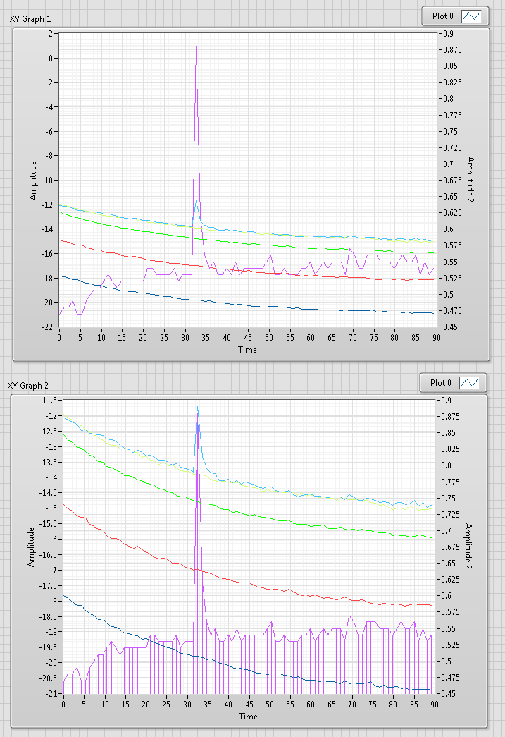
Vertical lines are used to display the frequency of breakdowns of machines (such as we post 1 X, 2 X, 3 X,... more harmonics).
Does anyone have a solution for this problem?
Thank you very much!!!
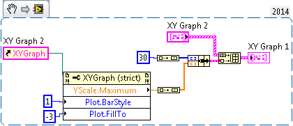
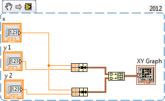
Here's a very quick example (LabVIEW 8.2)
Tags: NI Software
Similar Questions
-
Hi all
We have challenges to the vertical lines of the tables
Draw us lines between the horizontal lines. When data needed more space, the distance range for more data. But the vertical lines did not apply.
We found variable elasticity for vertical lines.
If you have any experience, please share it to us.
Thanks for once again,
NYF4 or Double click
NULL for repeat imagehttp://nyapex.blogspot.com/2010/07/vertical-line-for-tables.html
Mark useful or correct accordingly
-
horizontal line on waveform graph
Hello world!
I'm still new to Labview, but I am trying to add a horizontal line to a already established "histogram" on my graph of the waveform. How this code works is that it takes a force of a forceplate (this force Exchange) and trace it as a bar to the left of the graph target (it's their strength of target - height represents the amount of force they wish to exercise). Ideally, you would like these bars have the same height (the person exerting the force uses the same amount as their target). To make it a little easier for them to see the target height, I'm wanting to draw a horizontal line at the height of the target, but keep the bar chart so that they can see how far their strength exercised power comes from their target they grow stronger or softer. Is there an easy way to do this? Ideally I'd like the bar chart and line, but if there must be two lines (one for the target does not move and one for the force that would change) which is very good also.
Thank you for your advice and your entries!
Emily
Dear emmaline35,
you use a waveform graph, not a graphic. Graphic does not markers (which would be the most simple solution to mark the extreme).
There is a suggestion that I have not tried: http://lavag.org/topic/11199-adding-a-reference-line-to-a-waveform-chart/?p=67119 (some solitions partially work are suggested earlier in the thread, too)
Suggestion 2) If you need this marker (horizontal) and if your application is not computationally intensive (which does not seem so), I would use a chart and add a horizontal guide. That can be set programmatically: property node > XScale > [MarkerValues] but you will have to replot the graph for each newly received value.
See you soon,.
-
NIMAX, how to create a digital line for address GPIO
Please, let me ask you a question about IO port address the NIMAX and PC.
I have an industrial PC with available GPIO ports.
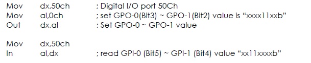
The example of reading and writing address was broadcast on the underside.
address port number is 50Ch.
How can I create the line digital 50Ch in the NOT-MAX.
Thanks for any suggestions.
MAX is useful for the hardware configuration of OR. Since this GPIO is not a product, NOR it will be not configurable in MAX.
-
Create the command line for the Dump file without having to install additional tools
I should automate the creation of dump files. It must to be command line and without installing tools such as ProcDumpTechNet.Microsoft.com/Sysinternals/dd996900, minidump or similar. I think that it is not a solution but if someone can help me.
This issue is beyond the scope of this site (for consumers) and to be sure, you get the best (and fastest) reply, we have to ask either on Technet (for IT Pro) or MSDN (for developers)* -
A couple of weeks ago, I bought a Photosmart 7520 to replace my HP D110. I posted a problem here and received a quick solution. I hope that this happen.
My problem is with vertical lines. The first file that contained a small table is a downloaded pdf file. When I printed this some vertical lines shifted just a little bit - small but noticeable. In fact, I did not notice it until I returned to it after printing an Excel spreadsheet and the problem of the vertical line noticing.
At this point, I opened HP printer Assistant, to maintain the printer and lined up the printing and print heads cleaning heads. Clean print heads print page showed several vertical line for verification and they were very good: no earthquake. I still once printed the pdf and again once there are sections that were slightly off. Then, I created a small table in Word and do print. Same result: small shift.
I made another clean and align another and another test print. Vertical lines have always shifted.
The move was in line. I mean, when I looked at two different prints of the table of the word, the movement was in the same places; identical.
The spreadsheet has multiple lines. As I scan down the vertical border between adjacent cells, I see a slight shift to the left on the bottom of the third cell. Sweeping down more of three cells the border comes to new right there where it was originally. That displacement, then back left again to the right, seems to repeat on all three rows.
That describes my problem.
Any ideas?
Thank you.
(My system is Windows7 64 bit running on a Dell StudioXPS computer).
I must admit that I forgot to update my request.
After a few days don't get any suggestion, I called the store where I bought the printer asking if I could come and exchange it for the same model. I was told that, because it was more than two weeks after the purchase, there will be an additional cost. Until I reluctantly paid the extra money, I called HP support.
Basically, what the tech support person is to uninstall the printer driver and install the latest version. Which corrects the problem. The process took time, but the result is that the printer works fine now, including the vertical lines.
-
Trying to insert 1 vertical line on xy-graph, but get more. Can someone give me a clue on what I did wrong?
Adding to my post: a point in this case is a pair of a x and a value of y

If you enter - Inf and + Inf for y values that you should always see a line (well, ignoring logarithmic scale
 )
) -
Action/Script Photoshop to place the vertical line at the center of the Image
How to create an action (or a script) in Photoshop that creates a vertical line in the center of the page?
Here is an example of what I'm looking for.

First go to view > rulers, then right-click on the rule, and the percent change units.
(so the action registers per cent and will work on different size documents)
Then drag a vertical guide at the Center, drag one to the top of the image and the other down.
(the goal is so the online tool is aligned with the top and down and you know where is the center of the document)

For action, you can use the online tool and just save lines from the top of the image down along the center guide.


-
How to separate two buttons with a vertical line
Hello
I'm trying to separate the 2 buttons in regions with a vertical line as Button1 . Button2. I intend to use an image of the vertical line for this. I put the image of a vertical line in the images of the workspace. How can I see the line between the buttons. Can I use the new "Image display" item for this purpose. Any input on this would be appreciated.
Tahnks,
NAV
Published by: Navarannan on 07-Sep-2010 05:34Yust create a between your buttons display element and put it in the source of this button a pipe:
|sign.
In the attributes of the feature display HTML form elements, you can put
s tyle="font-weigh t:bold;fon t-size:20px"or similar, to influence the layout of the sign of the pipe.
Denes Kubicek
-------------------------------------------------------------------
http://deneskubicek.blogspot.com/
http://www.Opal-consulting.de/training
http://Apex.Oracle.com/pls/OTN/f?p=31517:1
http://www.Amazon.de/Oracle-Apex-XE-Praxis/DP/3826655494
------------------------------------------------------------------- -
Can someone explain how to create a vertical content for a vertical display with the following dimensions: 43.1 x 11.8 x 7.5 in. / 1096.0 300,0 x 190 mm, using movement 5 x or Final Cut Pro X.
Thank you
Stuart35
You can set the dimensions for application projects when you initially installed a new project, or once the project is created.
New project
-On the file menu, select "new". This will bring up the project browser.
-In the upper right corner of the project tree, is the preset pop-up. Click on that and select "Customize".
-When custom is selected, you will see the fields width & height.
Existing project
-Type of command + J to display the properties for the project.
-In the Inspector, you will see the setting for the project (resolution, frame rate, etc.).
-Just change the width and the height.
-
Hello
my hp envy jo37tx has a vertical line for the last 6 months. Initially, he was gone as I move the screen up and down, but now this isn't diappear. No one knows the reason for this.
Thank you
According to the message that you have recently published, I want to confirm that it is a hardware problem and the screen needs to be replaced. I highly recommend Contact HP Support by phone to get help to get your Notebook diagnosed and repaired by an authorized HP Certified Engineer
You can also check your warranty here to check the status of the guarantee
Hope this helps, for other queries in response to the post and feel free to join us again
* Click on the white button on the right to say thank you Thumbs Up *.
Make it easier for others to find solutions by checking a response "Accept as Solution" if it solves your problem.
Thank you
GBL84
I'm not an employee of HP
-
Two background colors for the same waveform graph
Hello guys!
I have a question for you: I am a new user of labview, so please be nice!
So here's the deal: I just created a thanks 4 thermocouple temperature registration program.
In real time, I then have a waveform graph 4 curves as soon as I start my program. And in my program, I had a button that allows me to record the temperature in a file for a period of time at a certain frequency.
So, what I have is: I got my chart of waveform with a black background for example, and once I pressed the button, the background color will be changed automatically to highlight the part of the graph where the record occurs, then the background will return to the black after finished recording. In this way, on the same graph, I could say that registration took place from here to there by looking at the graph. I have two different background on the same graph.
I don't know how to change the background of a chart using the property node, but is it possible to do what I want?
I hope I'm clear. Otherwise, feel free to ask me for more details... I might post my vi if necessary
See you soon
Well, I know this is not exactly what you want to do, but you can try the following.
Change the color of the line on the chart when recording occurs.
You could therefore have a red line, then press on save, then it turns blue, then back to red.
And when that is confusing since you have 4 different lines on the chart 1,
You can change to a red line and a dotted red line, for example.
Would that be acceptable? If so, I can show you how to do this.
-
Multiple waveform graph, history of waveform card
Hello to all my colleagues.
I have problem with software of my purchase. I create software for the acquisition of 40 signals. I need to view and save these signals. I measure these signals with different frequencies (this depends on the user's selection), but the lowest frequency is 500 Hz and the highest is 2 000 Hz. Because I see a different size of X scale (5 sec - 60 dry), I decimate these signals for display and display only 100 samples per second.
I think that my problem is related to a very long history of waveform graph. When I display all signals in a single diagram, permanently signals are not displayed and the table is larger than the correct size of X-scale, means that the courses of the waveform graph freeze. I think the problem is connected only with display and no acquisition because I tried to check the measured data and there isn't any problem.
You have one any opinion how can I solve my problem?
Please, help me, because I'm out of ideas.
Thak you.
Here's my VI.
Double post,
Please find the thread here:
http://forums.NI.com/T5/LabVIEW/multiple-waveform-chart-history-of-waveform-charts/m-p/1762160
Best regards:
Tamas Szekely
Technical sales engineer
-
Save the Studio measure waveform graph as a file for reading later
Hello
I would like to know if there is an easier way to record data are rendered on a waveform graph (configured as a graphic of the band) to capture incoming data in the code and send copies of it to a file. It would be nice if there was a method to do this, with all relevant metadata stored in the file (color, etc.). Better yet, the file could then be opened in a labview application (for example, a TDMS file) for later review.
Thank you.
PS. I use VS2010 and MS 2010.
So, it looks like you already have all the data points. For metadata that you mentioned, line color, plot colors, point colors, line styles, etc. are all accessible from the properties so if you wish, you can retrieve all that data.
I think that upon return from t0 is the same compensation history, you can use the ClearData() method.
-
Type of input data for the graph waveform
Waveform graphs do not change the type of input data according to the wire. When I create a new chart that is set to double data type and does not change what I connect to waveform, so I copy graphics to another VI for appropriate indication. But the graphics don't accept complex data. How can I change the type of input data?
The graphics in vi you have posted behave properly on my machine.
Change according to the type of data that connect you to them.
Maybe something wrong with your installation?


Maybe you are looking for
-
The G5 is a Power PC
-
Where are the standard windows such as solitare games, etc.?
-
Plug MIC not recognizing external mic
Hello I have an Acer Aspire V5 - 572 G 8.1 Windows running and found that taking microphone does not recognize any external microphone that is placed in it. It does not detect the sound option despite the fact that all the drivers are updated. Does a
-
whenever I try to download something it says comctl32.ocx is missing the problem re - install. then I tried to solve the problems. I tried to download google chrome, but it says I need to upgrade my computer to the .NET then I tried to reinstall but
-
How to disable function keys (option of BIOS does not)
Hi, I bought a new HP Pavilion g6, where the keys F1-12 adjust the brightness, volume, etc. and I really feel like they have their original functions without having to press SHIFT + key or Fn + key. I already tried this: http://support.hp.com/us-en/d