As redundant N3024 switch configuration
Dear all,
Hi, I just get N3024 Dell as a main switch and X 1026 access.
I try to create the topology like this:

VLAN 10: 10.10.10.xxx/24
VLAN 20: 20.20.20.xxx/24
VLAN 30: 30.30.30.xxx/24
VLAN 40: 40.40.40.xxx/24
Just try using the interface vlan each switch.
Switch:
IP routing
interface VLAN 10
10.10.10.1/24 IP address
The interface VLAN 20
20.20.20.1/24 IP address
The interface VLAN 30
30.30.30.1/24 IP address
Interface port 2
switchport mode trunk
B switch:
IP routing
interface VLAN 10
10.10.10.2/24 IP address
The interface VLAN 20
20.20.20.2/24 IP address
The interface VLAN 30
30.30.30.2/24 IP address
I think that my config is far from complete and not best practices...
My question is, what should I configure on each N3024 Dell, so all them VLAN can connected to the Internet? (can create the support for the ip address of the Sonic Wall port)
Please please need your help.
Thanks before.
-The VRRP VLAN must be the same on both switches.
-That the master switch must have control of the track in place.
-The connection between the switch and the firewall must be that it is own VLAN and does not part of VLAN VRRP.
Here is a diagram that I put in place, it could help clear up some confusion.

Tags: Dell Switches
Similar Questions
-
Best Practice Guide for stacked N3024 switches
Is there a guide to BP for the configuration of the 2 N3024s stacked for the connections to the server, or is the same eql iscsi configuration guide.
I'm trying to:
1) reduce to a single point of failure for rack.
(2) make good use of LACP for 2 and 4 nic server connections
(3) use a 5224 with it's 1 lacp-> n3024s for devices of unique connection point (ie: internet router)
TIA
Jim...
Barrett pointed out many of the common practices suggested for stacking. The best practice is to use a loop for stacking and distributing your LAG on multiple switches in the stack, are not specific to any brand or model of the switch. The steps described in the guides of the user or the white papers generally what is the recommended configuration.
http://Dell.to/20sLnncMany of the best practices scenarios will change of network-to-network based around what is currently plugged into the switch, and the independent networks needs / requirements of business. This has created a scenario where the default settings on a switch are pre-programmed for what is optimal for a fresh switch. Then recommended are described in detail in white papers for specific and not centralized scenarios in a single document of best practices that attempts to cover all scenarios.
Express.ypH N-series switches are:
-RSTP is enabled by default.
-Green eee-mode is disabled by default.
-Frother is enabled by default.
-Storm control is disabled by default.Then these things can change based on the towed gear and needs/desires of the whole of society.
For example, Equallogic has several guides that recommendations of configuration detail to different switches.
http://Dell.to/1ICQhFXThen on the side server, you would like to look more like the OS/server role. For example a whitepaper VMware that has some network settings proposed when running VMware in an iSCSI environment.
http://bit.LY/2ach2I7I suggest making a list of the technology/hardware/software, which is used on the network. Then use this list to acquire white papers for specific areas. Then use these white papers best practices in order to ensure the switch configuration is optimal for the task required by the network.
-
IviSwitch loses value when sending, "configure the switch" configuration = TRUE
Hi all
We are currently assessing Teststand 4.1 with a multimeter keithley 3706 switch system.
After a first enthusiasm, thinking this tool with the meter switch fits perfectly our needs, real life seems difficult.
Between several other problems, we must say to the device, the channel "s1com1" and "s1com2" are strings of configuration.
Configure the teststand step: change the switch step IVI-> IVI, switching, configuration switch: channels "s1com1" Configuration = True
led to observable in both actions in Ni Spy:
GetAttributeViBoolean (..., "s1com1", _IS_CONFIGURATION_CHANNEL, VI_FALSE)
SetAttributeViBoolean (..., "s1com1", _IS_CONFIGURATION_CHANNEL, VI_FALSE)
manually call to this function of the interactive a CVI fp class works as expected (the VI_TRUE updated)
Is there any hint that we could do wrong? Currently, we are just before writing wrappers in cvi and jump all the wonderful Types of IVIStep in teststand.
Looking forward to any comments
David Clus
David-
This would have the same problem we discovered recently in our internal tests. For the problem that we found, we will probably include our fix in a next corrective patch. You can check if the problem persists if you change your locale in English in the control panel? If the problem no longer occurs, can you use this as a workaround for now?
-
LAG does not not after more Guide of switch Configuration for EqualLogic San steps in the document.
We use the information provided in the following document: i.dell.com/.../dell-networking-n4000-series-switch-configuration-guide-for-equallogic-sans.pdf
We have two switches of N4032F which are stacked and followed almost word for Word from this document. We do not use DCB. We are trying to set up a SHIFT and follow-up step 2.11 in the document, but it seems that the SHIFT does not work.
Switch 1:
serial interface fortygigabitethernet 1/1/1-2
No spanning tree portfast
active in mode channel-group 1
Switch 2:
interface series fortygigabitethernet 2/1/1-2
No spanning tree portfast
active in mode channel-group 2
However, when it was discovered after changing these settings it shows them as being inactive.

Can someone please help?
Thank you
Jeff
Thanks for the additional information. When the switches are stacked, they act as a logical switch. Then when you plug with an OFFSET you are basically creating a loop and hook up a switch on himself. Desempilement switches and just use the OFFSET for the interconnection of the switch and you should see the GAL go active.
-
The virtual switch configuration
Hello
I configured Vswitch on ESX4.0 connected with a teddy bear.
There are Cisco catalyst 4503 L3 switch configured with several VLANS at the other end. I have configured the switch port trunk with dot1q encap mode that ends on the ESX4.0 server. Service console is configured with IP default VLAN, which is accessible from the other VIRTUAL networks. One of the virtual machine with Win2k3 OS is installed, but after configuration, I am not able to ping default gateway of VLAN respective or any other property intellectual VLAN.
Can anyone guide me where I go wrong and how to correct the problem?
Set the Group of ports to the VLAN specific you want the virtual machine to be on. Do not put any VLAN ID in the virtual machine, just plug it into the port group. If you have other virtual machines, or other on this virtual machine network interface cards that need to connect to the other VLAN create other Port groups for each VIRTUAL local area network required.
-
is possible to configure the wan on Dell N3024 switch port
Hello
as I said in the topic. I got a new switch N3024 of Dell. I worked in before cisco, but dell is new to me. I have a few question to ask: -.
is that we can configure wan on that port?
is - this switch supports the aggregation of the ISL?
If Yes please share the switch manual
Thanks in advance
The WAN connection is made usually by creating a VLAN and assignment of an IP address in the same subnet as the device that it connects this VLAN.
Example:
Create VLAN 10
database of # vlan
VLAN # 10
For example let's say that 1/0/1 interface connects your firewall, which has an IP 10.10.10.1 30 assigned to its interface. This means that we would assign 10.10.10.2 30 to VLAN 10.
# interface vlan 10
# 10.10.10.2/30 ip address
Then place the interface 1/0/1 in access mode for VLAN 10.
# interface gigabitethernet 0/1/1
switchport mode access #.
# switchport access vlan 10
Enable the VLAN routing on the switch.
# ip Routing
Define a static route pointing out traffic at the firewall.
# ip route 0.0.0.0 0.0.0.0 10.10.10.1
Orders of trunking VLAN are very similar to the Cisco commands.
# interface gigabitethernet 0/1/1
switchport mode trunk #.
# permit switchport trunk VLANs 1-1024
Here is a link to the user's guides:
And here is another link to some useful white papers:
Hope this helps
-
the redundant switch configuration
We have a site with two servers of ESX4. Both servers have networking configured like this:

vmnic0 is plugged into a switch and vmnic2 is connected to another switch. However if the vmnic0 switch is plugged breaks down all closed virtual guest machines. Any ideas what I am doing wrong?
However if the vmnic0 switch is plugged breaks down all closed virtual guest machines.
You have VMware HA?
Set response of isolation 'leave the virtual machine' and check how much time is needed to move to the other switch.
But tuning configuration of the switch (for example with RSTP), you can reduce this time.
Then you can put this time (better if you double it) in HA advanced settings and re-enable the response of isolation.
André
-
Questions about N3024 switch by default - originate BGP
Here is the configuration of the two switches. I set up and rising BGP, passing of prefixes. I want 1 switch to send a default gateway to switch 2 and have the default installation of command on the next statement are created. I don't see the 0.0.0.0 route by default in the show ip bgp sum command, but which is detailed in the configuration guide. However, I don't see a default route 0.0.0.0 in the routing table for switch 2 at all and an error message that there is no default route available. Would I be missing here?
Config is below:
SWITCH 1
Configure
VLAN 50
output
VLAN 50
name "switchtest".
output
hostname "Switch_1.
location 1/0 1! Dell network N3024
battery
1 1 member! N3024
output
IP routing
!
loopback interface 1
IP 10.0.0.1 address 255.255.255.255
IP ospf area 0
output
interface vlan 1
DHCP IP address
output
interface vlan 50
172.16.0.1 IP address 255.255.255.252
IP ospf area 0
output
router ospf
router ID 10.0.0.1
10.0.0.1 network 255.255.255.255 area 0
network 172.16.0.0 255.255.255.252 area 0
output
!
item in gi1/0/1 interface
Description 'Switch '.
switchport access vlan 50
output
Server SNMP engineid local 800002a203f8b1566f36c4
router bgp 65001
router BGP 10.0.0.1 ID
172.168.0.0 netmask 255.255.255.252
10.0.0.1 netmask 255.255.255.255
172.16.0.2 neighbor remote - as 65002
neighbor 172.16.0.2 are created by default
output
output
Switch_1 #show ip bgp
BGP table version is 7, local router ID is 10.0.0.1
Status codes: s removed, * valid, > best, i - internal
Source codes: i - IGP, e - EGP? -incomplete
Network Next Hop metric LocPref path origin
------------------- ---------------- ---------- ---------- ------------- ------
* > 172.16.0.0/30 172.16.0.2 1 100 65002 I
* > 192.168.100.0/30 172.16.0.2 1 100 65002 I
* > I have 10.0.0.1/32 0.0.0.0 1 100 I
* > 10.0.0.2/32 172.16.0.2 1 100 65002 I
Switch_1 #show ip bgp sum
IPv4 routing... Enable
BGP Admin Mode... Enable
BGP router ID... 10.0.0.1
Local AS number... 65001
Traps ......................................... Disable
Maximum paths... 1
Maximum paths IBGP... 1
Default Keep Alive Time... 30
Default hold time... 90
Number of entries of network... 4
Number of PATHS... 1
Default metric... Not configured
Advertise default route... NO.
Redistribution:
Dist metric list of source route map
--------- ---------- -------------------------------- --------------------------------
Neighbor ASN MsgRcvd MsgSent State down time Pfx Rcvd
---------------- ----- -------- -------- ------------- -------------- ---------
172.16.0.2 65002 78 82 ESTABLISHED 0:00:23:24 3
Switch_1 #show ip route
The traffic code: R - RIP derived, O - OSPF derived, C - connected, S - static
B - Derived E - from outside, AI - BGP OSPF Inter zone
E1 - OSPF external Type 1, E2 - OSPF external Type 2
N1 - OSPF NSSA external Type 1, N2 - OSPF NSSA external Type 2
S U - unnumbered Peer, L - flight road
* Indicates the best route (the lowest metric) for the subnet.
No default gateway is configured.
*10.0.0.1/32 C [0/1] directly connected, Lo1
B *10.0.0.2/32 [20/1] via 172.16.0.2, Vl50
10.0.0.2/32 [110/11] via 172.16.0.2, Vl50
*172.16.0.0/30 C [0/1] directly connected, Vl50
B 172.16.0.0/30 [20/1] via 172.16.0.2, Vl50
B *192.168.100.0/30 [20/1] via 172.16.0.2, Vl50
192.168.100.0/30 [110/20] through 172.16.0.2, Vl50
SWITCH 2
Configure
VLAN 50 100
output
VLAN 50
name "SwitchTest".
output
VLAN 100
name of the 'Switch '.
output
hostname "Switch_2".
location 1/0 2. Dell network N3024F
battery
1 2 Member! N3024F
output
IP routing
!
loopback interface 0
output
!
loopback interface 1
10.0.0.2 IP address 255.255.255.255
output
interface vlan 1
DHCP IP address
output
interface vlan 50
IP 172.16.0.2 255.255.255.252
IP ospf area 0
output
interface vlan 100
IP 192.168.100.1 255.255.255.252
output
router ospf
router ID 10.0.0.2
10.0.0.2 network 255.255.255.255 area 0
network 172.16.0.0 255.255.255.252 area 0
network 192.168.100.0 255.255.255.252 area 0
output
!
interface item in gi1/0/23
switchport access vlan 100
output
!
interface item in gi1/0/24
Description 'Switch '.
switchport access vlan 50
output
Server SNMP engineid local 800002a203f8b156530097
router bgp 65002
router BGP 10.0.0.2 ID
172.16.0.0 netmask 255.255.255.252
192.168.100.0 netmask 255.255.255.252
10.0.0.2 netmask 255.255.255.255
neighbor remote - as 65001 172.16.0.1
output
output
Switch_2 #show ip bgp
Version of BGP table is 9, local router ID is 10.0.0.2
Status codes: s removed, * valid, > best, i - internal
Source codes: i - IGP, e - EGP? -incomplete
Network Next Hop metric LocPref path origin
------------------- ---------------- ---------- ---------- ------------- ------
* > I have 172.16.0.0/30 0.0.0.0 1 100 I
* > I have 192.168.100.0/30 0.0.0.0 1 100 I
* > 10.0.0.1/32 172.16.0.1 1 100 65001 I
* > I have 10.0.0.2/32 0.0.0.0 1 100 I
Switch_2 #show ip bgp sum
IPv4 routing... Enable
BGP Admin Mode... Enable
BGP router ID... 10.0.0.2
Local AS number... 65002
Traps ......................................... Disable
Maximum paths... 1
Maximum paths IBGP... 1
Default Keep Alive Time... 30
Default hold time... 90
Number of entries of network... 4
Number of PATHS... 1
Default metric... Not configured
Advertise default route... NO.
Redistribution:
Dist metric list of source route map
--------- ---------- -------------------------------- --------------------------------
Neighbor ASN MsgRcvd MsgSent State down time Pfx Rcvd
---------------- ----- -------- -------- ------------- -------------- ---------
172.16.0.1 65001 83 82 ESTABLISHED 0:00:24:32 1
Switch_2 #show ip route
The traffic code: R - RIP derived, O - OSPF derived, C - connected, S - static
B - Derived E - from outside, AI - BGP OSPF Inter zone
E1 - OSPF external Type 1, E2 - OSPF external Type 2
N1 - OSPF NSSA external Type 1, N2 - OSPF NSSA external Type 2
S U - unnumbered Peer, L - flight road
* Indicates the best route (the lowest metric) for the subnet.
No default gateway is configured.
B *10.0.0.1/32 [20/1] via 172.16.0.1, Vl50
10.0.0.1/32 [110/11] via 172.16.0.1, Vl50
*10.0.0.2/32 C [0/1] directly connected, Lo1
*172.16.0.0/30 C [0/1] directly connected, Vl50
*192.168.100.0/30 C [0/1] directly connected, Vl100
Switch_2 #show ip route 0.0.0.0
The traffic code: R - RIP derived, O - OSPF derived, C - connected, S - static
B - Derived E - from outside, AI - BGP OSPF Inter zone
E1 - OSPF external Type 1, E2 - OSPF external Type 2
N1 - OSPF NSSA external Type 1, N2 - OSPF NSSA external Type 2
S U - unnumbered Peer, L - flight road
* Indicates the best route (the lowest metric) for the subnet.
No default gateway is configured.
No route found.
Solution:
Dell switches need to be turned on in the config.
router bgp * AS number *.
default-information originate always
-
The proSafe (JGS524E + GS116E) Switches: Configuration Management Web GUI in VLAN specific
Hello
I use a JGS524E and a GS116E. The two are connected via a 802. 1 q uplink with all defined VLANS in him.
A 802. 1 q other interfaces goes to a pfsense firewall, which serves as a router and dhcp server for each VLAN that I use.
How can I configure the switches plug are in one VLAN specific and get his IP address of the dhcp server in this VLAN?
At present, it seems to be random access: it is not predictable that range from intellectual property, it takes its IP configuration via dhcp...
How management function works internally?
Thank you
Markus
Hello
Thank you. I tried it out, but the behavior seems to be a little different:
I configured a static IP address for the switch (10.1.0.13 / 24). I have access to the switch web gui via the ip address of the host of a host directly connected (connected via a trunk port, where I put 1 VLAN on the trunk), but it is all the same, what VLAN that I use:
When it is connected to the VLAN 1 I have access, but also through 10 VLANS, VLAN 20 and so forth (assumed, I configure my computer appropriate staticly in the IP network, for example 10.1.0.20 / 24). So it seems not be limited only to the VLAN 1. You have access to each vlan, only the IP configuration must be in the same network.
I'm not sure, how it behaves when cascading the two switches, I have not tried.
If this information can be useful for other users with the same question about this switching product line.
For me, this behavior is not very well implemented from my point of view. For security reasons, you must limit access to the administration, for example by allowing access from a specific hardware port or a vlan. With the effective implementation, centralized management for a cascade topology is not easy to set up, perhaps because the behavior is not very clear and not documented in the manuals.
Mentioned on the edge: there is no available TLS/SSL encryption when accessing the web gui (not https). So the password is transmitted in clear text... not a very good idea, I think.
Thanks a lot for your help.
Best regards
markusd112
-
The Switch configuration and Wi - fi router in the same network
Hi team,
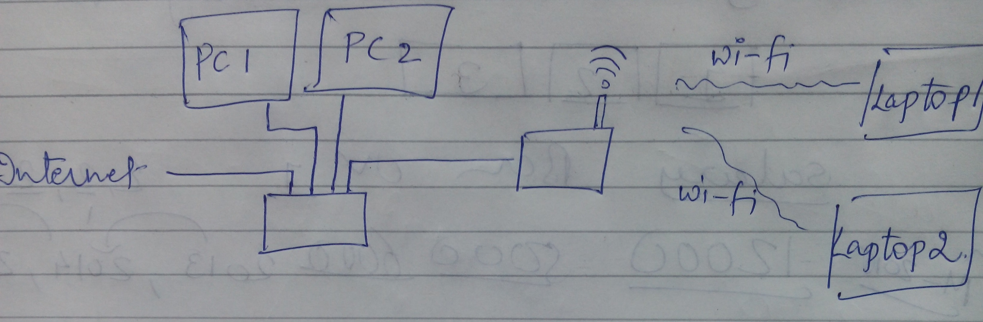
I have here is the configuration currently as below in the image. To describe the same internet cable is connected to a Cisco switch, which is connected to the PC in LAN (wired). A switch output is connected to the entrance of the wireless router Netgear Nighthawk AC 1900 Smart model of WiFi router # R6900. Wireless devices (laptop) are connected by the router.
Each device has internet access. However, I am unable to run software LAN or unable to share any file of devices connected to the switch to the connected wireless devices. I can't ping any device the device wireless wired.
Can anyone suggest what are the settings that I should do or what are the steps I should follow that will make wireless and wired devices in the same network.
PS Plus early I tried the internet connection to the wireless router and then out of the router to pass, which has solved this problem. But slowing down my internet speed in wired devices. So, is it possible to have all devices in the network even with the current configuration?
Thanks in advance.
Best,
Hardik
I made wi - fi router reset hardware and configured in Access Point mode, that solved my problem.
-
32 x 1 double switch configuration PXI-2527 and TB-2627
Looking for configuration of the PXI-2527 at double 32 x 1 using a TB-2627 terminal block. Under the OR rocking support for topology multiplexer NI PXI/SMU-2527 1 double wire 32 × 1 -.
(link - http://zone.ni.com/reference/en-XX/help/375472C-01/switch/2527_dual_1-wire_32x1_mux/) it displays the names of software for different PIN numbers. I don't care actually on this subject because I use the Terminal Board, but what worries me is that the diagrams represent Ch0-Ch31 connection com0 + and Ch32-Ch64 to com1 + and there is NO mention of com0 - or com1. However, the NI TB-2627 installation instructions, table 4 shows the mapping Terminal double 32 x 1 1 - Wire topology. In this map, IT lists a software name and the name of Terminal for com0 - and com1-.
My question is, if com0 and com1 - are not listed in the manual switch why are the listed in the TB-2627 manul and what is it in this configuration?
Thanks for your time.
In the Setup instructions for the double configuration 32 x 1 TB-2627, she mentions Com0 - and Com1 - as a reference to inform the user what pin connects to since this same module can be used with other topologies. It is unnecessary for the topology of 32 x 1 information double since the switch card does not use these channels for this particular topology. Information is available for your reference, but does not neet to be connected to anything.
Please let me know if any of this is unclear.
Kyle K.
-
GANYMEDE + with 3560 cisco switch configuration issue
Hi Forum,
Here's my setup GANYMEDE + on my cisco 3560 switch and my question is, how can I configure the switch, if I would not type enable after I put the user name and password? with configs below, users will need to type activate whenever they connect to the switch in order to enter the user exec mode. Please let me know if there is something missing in my configs to help me avoid typing 'enable '.
Thanks in advance,
MacBookAir: ~ MacBook$ ssh [email protected]/ * /.
Password:
Switch > en
Switch #show run | include the aaa
AAA new-model
AAA server Ganymede group + mpcc
AAA authentication login default group Ganymede + local
activate the default AAA authentication no
AAA authorization exec default group Ganymede + authenticated if
AAA authorization commands 1 default group Ganymede + authenticated if
AAA authorization commands 15 default group Ganymede + authenticated if
start-stop radius group AAA accounting dot1x default
AAA accounting exec default start-stop Ganymede group.
orders accounting AAA 1 by default start-stop Ganymede group.
orders accounting AAA 15 by default start-stop Ganymede group.
AAA accounting system default start-stop Ganymede group.
AAA server RADIUS Dynamics-author
AAA - the id of the joint session
Switch #.
Hello
Add the level of privilege 15 control VTY line configuration.
line vty 0 4 [..] privilege level 15 !
Concerning
-
The switch configuration of 6500 catalyst for IPS Inline the METHOD works
I understand how to configure the switch Catalyst 6500 so that the monitoring of ports are access ports in two VLAN separate operation online.
However, I don't see any document that describes how the desired VLAN traffic gets forced through the IPS.
"Promiscuous" mode, you can use copy/capture VACL and forwards traffic wished the METHOD of analysis. I don't see how to get traffic desired through the IPS.
Note that the 6500 host is running native SXE IOS 12.2 (18).
Thanks for any help.
A transparent firewall is a pretty good comparison.
Say you have vlan 10 with 100 PCs and 1 router for the network.
If you want to apply a transparent firewall on this vlan you can put not just the Firewall interface on vlan 10. Nothing would go through the firewall.
Instead, you need to create a new vlan, say 1010. Now you place the Firewall interface on vlan 10 and the other on the vlan 1010. Nothing is still going through the firewall. So now move you that router from vlan 10 to vlan 1010. Everything you do is to change the vlan, IP address and the mask of the router remain the same.
The firewall transparent bridge vlan 10 and vlan 1010. The SCP on the vlan 10 ae is able to communicate and through the router, but must go through the transparent firewall to do.
The firewall is transparent because there no IP Route between 2 VLANS, instead, the same IP subnet is on the VLAN and the transparent firewall ensuring the beidges between the 2 VLANS.
The transparent firewall can do firewall between the SCP on the vlan 10 and the router on vlan 1010. But PC has vlan 10 talks for PC B on vlan 10, then the transparent firewall does not see and cannot block this traffic.
An InLine sensor is very similar to the transparent firewall and will fill between the 2 VLANS. And similarly an InLine sensor is able to monitor InLine between PCs traffic on vlan 10 and the router on vlan 1010, but will not be able to monitor the traffic between 2 PCs on vlan 10.
Now the PC on the other vlan and the router on a virtual LAN is a classic deployment for the sensors online, but your VLAN need not be divided in this way. You can choose to place some servers in one vlan and desktop to another vlan. You subdivide them VLAN to whatever the logical method for your deployment.
Now for the surveillance of several VLANs the same principle still applies. You can't control traffic between machines on the same vlan. So for each the VLAN that you want to analyze, you will need to create a new vlan and divide the machines between the 2 VLANS.
In your case with Native IOS, you are limited to only 1 pair of VLAN for InLine followed, but your desired deployment would require 20 pairs of vlan.
The IPS 5.1 software now has the ability to manage the 20 pairs, but the native IOS software doesn't have the ability to send the 40 VLAN (20 pairs) to the JOINT-2.
Changes in native IOS are in testing right now, but I have not heard a release date for these changes.
Now cat BONES has already made these changes. So here is a breakdown of basic of what you could do in the BONE of cat and you can use to prepare for a deployment native IOS when it came out.
For VLAN 10-20 and 300-310, you want monitored, you will need to break each of those VLANs in VLAN 2.
Let's say that keep us it simple and add 500 to each vlan in order to create the new VLAN for each pair.
Therefore, the following pairs:
10/510, 511/11, 12/512, etc...
300/800, 801/301, 302/802, etc...
You configure the port to probe trunk all 40 VLAN:
set the trunk 5/7 10-20 300-310 510-520 800-810
(And then clear all other vlans off this trunk to clean things up)
In the configuration of JOINT-2 create the 20 pairs of vlan inline on interface GigabitEthernet0/7
NW on each of VLAN original 20 leave the default router for each LAN virtual vlan original to the vlan 500 +.
At this point, you should be good to go. The JOINT-2 will not track traffic that remains inside each of the 20 VLAN original, but would monitor the traffic is routed in and out of each of the 20 VLAN.
Due to a bug of switch, you may need to have an extra PC moved to the same vlan as the router if the switch/MSFC is used as the router and that you deploy with a JOINT-2.
-
Setup
Cisco Catalyst 2960-S running 15.0.2 - SE8
Under Centos freeRadius 6.4 RADIUS server
Client (supplicant) running Windows 7
When Windows client is connected to the port (port 12 in my setup) with authentication of 802. 1 x active switch, show of Wireshark that catalyst sends ask EAP and the client responds with EAP response. But it made not the request to the Radius server. The RADIUS test utility 'aaa RADIUS testuser password new-code test group' works.
Here is my config running. Any advice would be greatly appreciated.
#show running mySwitch-
mySwitch #show running-config
Building configuration...Current configuration: 2094 bytes
!
version 12.2
no service button
horodateurs service debug datetime msec
Log service timestamps datetime msec
no password encryption service
!
hostname myswitch
!
boot-start-marker
boot-end-marker
!
activate the password secret 5 $1$ Z1z6$ kqvVYRQdVRZ0h8aDTV5DR0 enable password!
!
!
AAA new-model
!
!
AAA dot1x group group radius aaa accounting dot1x default start-stop radius authentication group!
!
!
AAA - the id of the joint session
1 supply ws-c2960s-24ts-l switch
!
!
!
!
!
control-dot1x system-auth
pvst spanning-tree mode
spanning tree extend id-system
!
!
!
!
internal allocation policy of VLAN no ascendant interface FastEthernet0 no stop ip address!
GigabitEthernet1/0/1 interface
!
interface GigabitEthernet1/0/2
!
interface GigabitEthernet1/0/3
!
interface GigabitEthernet1/0/4
!
interface GigabitEthernet1/0/5
!
interface GigabitEthernet1/0/6
!
interface GigabitEthernet1/0/7
!
interface GigabitEthernet1/0/8
!
interface GigabitEthernet1/0/9
!
interface GigabitEthernet1/0/10
!
interface GigabitEthernet1/0/11
!
interface GigabitEthernet1/0/12
switchport mode access
Auto control of the port of authentication
dot1x EAP authenticator
!
interface GigabitEthernet1/0/13
!
interface GigabitEthernet1/0/14
!
interface GigabitEthernet1/0/15
!
interface GigabitEthernet1/0/16
!
interface GigabitEthernet1/0/17
!
interface GigabitEthernet1/0/18
!
interface GigabitEthernet1/0/19
!
interface GigabitEthernet1/0/20
!
interface GigabitEthernet1/0/21
!
interface GigabitEthernet1/0/22
!
interface GigabitEthernet1/0/23
!
interface GigabitEthernet1/0/24
!
interface GigabitEthernet1/0/25
!
interface GigabitEthernet1/0/26
!
interface GigabitEthernet1/0/27
!
interface GigabitEthernet1/0/28
!
interface Vlan1
IP 10.1.2.12 255.255.255.0
!
IP http server
IP http secure server
activate the IP sla response alerts
recording of debug trap
10.1.2.1 host connection tcp port 514 RADIUS-server host 10.1.2.1 transport auth-port 1812 acct-port 1646 timeout 3 retransmit testing123 key 3.
Line con 0
line vty 0 4
password password
line vty 5 15
password password
!
endinterface GigabitEthernet1/0/16
!
interface GigabitEthernet1/0/17
!
interface GigabitEthernet1/0/18
!
interface GigabitEthernet1/0/19
!
interface GigabitEthernet1/0/20Have you run wireshark on the server because the request to switch? If so you make sure that there is a response from the server? For Windows network POLICY Server (I've never tried Centos), you must ensure that the request is related to a policy which then authenticates, or denies access. Usually, it is a matter of such attributes and the seller.
Regarding the configuration, it seems a bit out of the AAA. Try to remove the:
line "aaa dot1x group service radius authentication" and this by using instead:
"aaa dot1x default radius authentication group". After the dot1x word you are supposed to provide a list of the authentication or the default Word if you do not want to use a list.
-
The ISE Cisco switch configuration
Hi experts,
I got the following network:
Devices-> switch access-->--> access switch central office switch-> ISE Server
All switches are capable IOS for the 802. 1 X and configurations of AAA for ISE to manage network devices. However, I read in the guide on the configuration of the switches in preparation for the deployment of the ISE of CIsco, but I wonder what should I configure switches for access and basic switches or only configure the switches for access to EHT?
Thanks for your time to read!
If all clients are non-DHCP clients, then no configuration is based or distribution at all.
But you may need to search different options of profiling, if the customers are not active DHCP. Access switch supports the function of detection IOS? Would be very useful to have such a that it would send important profiling information at ISE. You may need to use the right options for ISE of profiling to determine the details of the endpoint.
Concerning
Vivek


Maybe you are looking for
-
App store takes to always load can not download a purchased list player
As the subject says about an hour ago I started to have problems with a drive (installed from the app store) does not. I had to keep killing the process command line. Finally, I uninstalled the app. Then when I went back to the App Store and it start
-
Satellite M40 - how to use the recovery cd
I have a laptop Toshiba Satellite M40 using XP HomeMy anti virus has caught a virus and delt with him. He told me to reboot, which I did. When he started toward the high winlogin.exe TI displayed cannot start because it is missing shell32.dllI clicke
-
files to clear the cache does not work
I tried to remove some cache safari files, but the files in the cache keep coming back. I'll explain how I tried to delete them: I clicked the button of safari on the top left of the screen---> Preferences---> Privacy---> details (next to remove all
-
HP Pavilion dv7 Notebook microphone correct for recording live music
If you are looking for the plug for the microphone - branch for the Pavilion dv7 Notebook intention is to record live Piano. I tried several microphones, but impedance must not be appropriate as the volume is very low during recording.
-
What are printers AIO a duplex scanning?
Hello! You don't know if it's the right place for this question, but unfortunately, looking for HP products somehow missed the filter to display AIOs compatible double-sided scanning. I hope someone who knows the products can help me on this. I'm loo