Battery Circuit diagram
Hi all
I need dell Inspiron N5010 15, Service tag:ADMIN NOTE: maintain the label removed by privacy policy >, battery circuit diagram. Please help me where I can download?
OMAIS,
There is no download for Dell computer Schematics for any product and are not to me for distribution.
Tags: Dell Laptop
Similar Questions
-
where can I find the chassis for the import file in MAX to draw the circuit diagram before you buy
where can I find the chassis for the import file in MAX to draw the circuit diagram before you buy
chassis: NI SMU-1078
ini file to import into MAX
See attachment
THX
Hi again Koen,
Unfortunately, you can't simulate a complete PXI system, so we do not have the ability to simulate a PXI controller unit. The simulation, you can do is to set up the cards you want to use in you.
concerning
Lars -
diagram of the battery for 3000 microsoft wireless mobile mouse
I just need a diagram of the door of the battery compartment for 3000 microsoft wireless mobile mouse. the silver metal piece is out and I need to see HOW
to reattach it properly so it will stay when I close the lid or the door to the battery compartment. Touch the + end of the battery to operate.Did you find the Mobile Mouse 3000 battery door diagram you are looking for last year?
I have the same situation. I don't need suggestions to inform microsoft of warranty. This is why you and I asked for the diagrams. If you have the diagram, or you can send me a photo of the battery door configuration, would be great. Thank you -
Are there templates ready-made for circuit or wiring diagrams in Illustrator?
I need circuits diagram with the standard symbols for resistors, capacitors, switches, etc.. Someone * must * have done this in Illustrator before! Free or reasonable basis for games available?
A Google search for wiring diagrams should show you some. Electronic symbols would be another good choice.
You will find once you know what each symbol looks like that they can easily be recreated in illustrator.
You can even find a police company who created the electronic symbols.
-
HP Pavilion 17 Laptop: battery connected, not charging AND battery unaccessable
In recent months, at one point, my battery would indicate nn % (plugged in, does not support) and maintain this accusation so much it was plugged. Running on the battery, the charge would eventually diminish and in order to get the battery charge again, I went through the process of uninstalling the compatible battery control method ACPI in Device Manager. Usually within 24 hours, choses things would be back to plugged in, does not support. However, that is no longer to fix the problem. (When it was a question the indicator next to the place where the power adapter is plugged blue flash. Also, I upgraded from 8.1 to 10 a few weeks ago, but this question was held for a few months now).
Now the battery is 2% (plugged in, does not support) and when I use the HP Support Assistant to check the battery, I get the message "control of battery HP could not access the battery. I did a hard reset, reset the BIOS and updated the BIOS, to anything will do. If I unplug the adapter, the computer turns off.
Suggestions of additional corrections? I saw a further suggestion to perform a system recovery but I did not yet a recovery disk to win 10 (I don't have one for victory 8.1), and it would make a difference anyway since no plugged in, charging problem took place under win 8.1?
Hi @shmay7,
From the information provided, I think it's a problem with the connection between the laptop and the battery. It might be something wrong with the point of contact between the battery and the portable or to the battery circuit. It is better to have another battery, so you can try it with the laptop. The creation of recovery media should not be affected by the problem of power with the battery is not installed.
-
Hello all,.
I have a beautifully SCB-68 connector block 68 pins. Can anyone provide me with the wiring diagram?
I went through the guides provided, but I have a few questions.
(1) how exactly work the switches?
(2) what is the need to provide + 5v to the part of conditioning of signals? (As for signal conditoning, we use some resistors and capacitors)
(3) where do we always connect us our signal? It is always the terminals screw or is it depends on the requirement of signal conditioning?
(4) if we use a conditioning of signals, which are input terminals? And what con terminals signals reaching data acquisition?
Concerning
-Vaidhin.
Hey,.
the Circuit diagram is shown to these PDF on page 82-83. (SCB-68 68-pin shielded connector manual user Block)
The sensor you want to use is never connect with the Terminal screw,
The switches have the following functions:
S1--> 5V supply
S2--> DGND
S3--> AIGND
S4--> PES or differential measurement
S5--> (cold junction Compensation) CJC
Best regards
Basti
-
Connection diagram DAQ Asst & error 50103
Hello LabVIEW community.
I'm trying to integrate two different screws that require an AIGND on my SCB-100.
The SCB-100 has two distinct AIGNDs (pinout of the 1 and 2), but in the two screws of the DAQ Asst I use, pinout 2 asks the circuit diagram for the two.
I think that leads to a mistake of 50103 on reserved resources.
Is it possible to switch, one of the AIGND of data acquisition for pinout 1 assistants?
Thank you all for your help.
Sincerely,
The reasons are common and are totally unrelated to the error-50103. The error is because you are using two different data collection Assistants. Have you done a search here of this code or explanation? Use a simple DAQ Assistant with several channels.
-
'no contact' bump in the wiring diagram
A casual user of Illustrator, I was just store a circuit diagram so that I can include a copy in a FrameMaker document own .eps. To my surprise and satisfaction, I managed to add a bump "contactless" in a path by adding an anchor point normal to the West of the intersection, adding an anchor of Bézier point to the East, and a movement of the Bézier handles until the North-South line.
Question: what is the trick to ensure that the "hump" is centered horizontally - in other words, making sure that the anchor points East and West are the same horizontal distance from the North-South line?
Thanks in advance!
Without seeing the problem, it is close can't say you anything other than read the documentation.
What you can do, is build your symbol on a semicircle like this:

The smart guides then lets this point. The power of the Smart - Guides Vectips
-
Satellite Pro 480CDT does not start (even in BIOS)
Hi all
I just hand on a Toshiba Satellite Pro 480CDT
I had to work with the original power supply (on an inverter plugged into my 12v cars I wasn't close to 240 v power outlet)
It worked very well, it boots into Windows 98 and I played with a few programs (Media Player and defragmentation)
I got it defragment for about 5 minutes, while charging via the car converter, however it froze and I had to hold the power button to restart.
When I tried to next turn on the screen remains empty, the hard drive is not turn and there is only the power LED and battery LED that lights up.
He let me press the function key that lights up the fn LED on top of the keyboard, but then after a few presses of lighting stops.
I opened the case and concluded that there are two batteries of the bios, the look at where they are plugged into the main Board, there is green type of corosion on the pins, I removed the plugs (who might add when it is very difficult to remove because of the coros), I cleaned the plugs (male & female) with a pen of WD40 and plugged in I got a voltmeter on them and they demonstrate tension and also show higher voltage when the power supply for laptop is connected, then it means they are load or at least tension.
After doing this I go up the laptop, but it still suffers from the same problem?
Please what could someone help or give me a little advice? My next event is the power supply Board but wanted to get some ideals before hand.
Thanks in advance.
Pete
> after doing this I go up the laptop, but it suffers still from the same problem?
His pity to hear that your baby dead :(
But if we move to a diagnosis of material, I doubt someone here might be able to point in the right direction if his motherboard problem, it would be really difficult to solve this problem without using special tools, circuit diagram of motherboard and of course experienceI think you should check the modules memory vivid faulty ram could affect the laptop everything is just speculation
-
Can someone help me find a diagram of circuit for my computer toshiba laptop satellite pro 4300. Including the Council of the drive battery.
Hello
Unfortunately, you won't find any of the circuit diagrams for Toshiba laptops on the Toshiba site. The Toshiba service partner has information on laptops.
I studied a bit on the net and found this site:
http://www.manualsparadise.com/ShowProductsForModel.do?model=M42292627It seems that you can buy there some instructions.
-
Satellite P10-317
* Symptoms *:
External DC LED stays on, but battery LED turns OFF (from green or orange) and laptop running on battery power only (Toshiba Power Management panel says that it has external DC AND the battery runs down). Disconnect and reconnect external DC does not cure but put into hibernation and resume the battery LED lights up again and he fled the external domain controller. If no battery is not connected, laptop just dies. Unfortunately, the problem is very intermittent. The battery is new and normally charges/discharges.
* Diagnosis * (tentative): the DC regulator on board is dying
* Question *: does anyone have the circuit diagrams? (anyone else seen this problem & what is the cure?)
Thank you
Julian
Hello
AFAIK this diagram is part of the maintenance manuals and is not a public document. Because of that I am quite skeptical that someone can help you with it. You can try to contact the nearest authorized service provider. They have these documents, and perhaps they are ready to help you.
Make a call.
-
HP G61-110SA - is no longer start or charge
Hi all
My battery died while it is plugged. I then noticed that the light next to the power supply wasn't on.
I tried a new charger, a battery and replaced the cable adapter on the side of the laptop on the motherboard. Still no charge neither start-up.
The LED will only Flash is marked LED2 on the motherboard or a lightning is used (power) on the case in the main proceedings.
Any ideas guys?
Those are the components on the motherboard and would require a technician with access to the printed circuit diagrams or really good electrical knowledge. You can get in an area where you might start thinking to apply the money towards a new machine against the cost of the repair.
-
Hello Helpers,
My Tecra 9000 IGH with Windows XP model has two usb ports dead and taken from mouse. From what I've read, it's a defect with this model. The USB ports are on a separate module that is plugged into the main Board.Is the fault on the set of the USB module or on the main Board or the fault lies in the power plug. Is the fault of the joints for example dry easily repairable, where a quick touch of a soldering iron can redo them. Does anyone have a circuit diagram which would make tracing easier fault.
I had partially circumvents the problem by using a USB card, but this often causes freezing the computer and my laptop hard drive will not work with it.
Any help appreciated.
Linlithgow your sunny.
DerekHello Derek
On this path, it is not easy to say what the problem is here, but I guess there is a contact problem. It is really not easy to say it's the problem motherboard or separate module itself. I think that it should be checked on professional way.
The second problem is the scheme of construction. As far as I know that is not a public document and you'll be lucky if anyone has it for you. I know that you will not be satisfied by my suggestion, but I think the best way is to communicate with the technicians and talk with them. Maybe there really small problem and can be cheaply repaired.
Good luck!
-
Replacement of transistor on Satellite L10-104
Hello everyone,
I have a Satellite L10-104. My problem is that my monitor didn' rooms discovered anything. I turn on my laptop and it works but I don't see anything. I saw that there is a Transistor or something like that on the motherboard, which is destroyed.
It is in the close not USB-slot on the back of my laptop. It is located next to the resistant R8. I want to change the unit of construction, but I can't read the label. I can just read w... but the rest is destroyed. I know it's a bad description, but I hope someone can help me.
I need the name of this thing. Maybe someone can give a circuit diagram, or something like that, for me.
Best regards.
CarinaDon t think that someone here will be able to help you because the patterns of the motherboard are not for public use so no one here could post a link or anything that would lead to this teaching
I think your last option is the maintainer authorized Toshiba in your country
But I put t think it would be possible to repair the motherboard on the simple fact is that you need to remove this small part, with the help of a soldering station if you need experience in electronics and soldering
-
Attach a current 50 Ohm with CMOS port hungry VCO
Hello world
This is our first post on NEITHER.

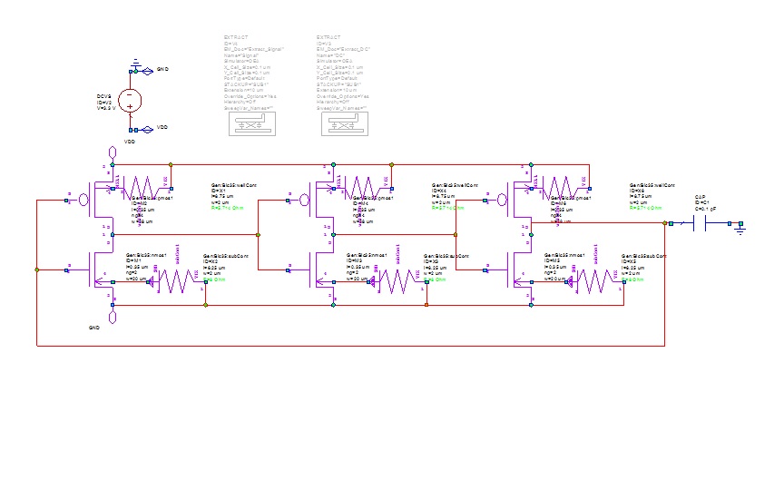
- We are working on the design of a current hungry VCO using the parameters of the model TSMC 180 nm. The problem we are facing is by attaching a port 50 ohms for the observation of its release. The port of 50 Ohm collapses at the exit, while a port GOhm 50 gives a good yield with good swing.
We need a port of 50 Ohm to check the power spectrum of output oscillator noise, tuning range, etc.. We do not understand what is happening.
- In the example of the ring oscillator AWR, an output capacitor was used to measure the output. Why is it used?
Here, too, a port of 50 Ohm collapses exit, while a port GOhm 50 provides a good return. We work for the range of frequencies; 1 GHz to 6 GHz. is it possible for the impedance of 50 ohm for all frequencies port?
We are attaching the circuit diagram. Please help us.
The output power is almost nil, because P = V ^ 2 / R and the charge is such a great resistance. Therefore, the power consumed is actually the sum of the power delivered by the power of DC voltage, which is actually the liveries of the source of the V1 power (other sources provide very little energy). The measure of your choice is non-linear > power > PT, measured using solenoid. V1, with DC_V.V3 to be used for the x-axis.
- We are working on the design of a current hungry VCO using the parameters of the model TSMC 180 nm. The problem we are facing is by attaching a port 50 ohms for the observation of its release. The port of 50 Ohm collapses at the exit, while a port GOhm 50 gives a good yield with good swing.

Maybe you are looking for
-
Touch screen of my laptop does not work after update my drivers to date. I opened Tablet PC setting, he said: "there is no pen or touch input available for this view. (I used the shortcut to open the parameter because the Tablet PC set disappeared in
-
Qosmio G32 HD DVD does not play on Vista Ultimate
I have installed vista Ultimate on my Qosmio. All it's OK: I have no problem with audio and also I play DVD.But I can't watch HD. Can you help me. Thank you
-
How can I remove the irritant "to the Home Pages?
Simple as that. How can I remove them irritating and superfluous 'Welcome to Pages' pages 5.6.1? Concerning
-
I have a Canon Powershot G9 and I would like to be able to trigger the camera remotely using a wireless remote control. There is no (apparent) plug to allow me access to this function The mini - USB port (under the digital 'AV Out' flap) allow me in
-
I can't activate windows8, 0xC004C003 error
Original title: I can not activate windows8 I can't activate my windows 8 he tried many times it keeps saying error 0 * C004C003, nobody knows how to help me