Buffer size different sampling rate.
Hello
I'm new to Labview and me has encountered a problem.
I did some measurements using two Renault and continuous type used samples. One device was NI 9239 and this one has a sampling frequency possible other than the size of buffer that I put. I put the size of the buffer of 3000 and the rate of possible samples of the device were 2941 and 3125.
From what I understand, this type (continuous type of samples) the size of the buffer is full and send it to the computer.
My question is this: my device sample rate is 3000 or 3125?
Why do you ask? You say that you know that a sampling rate of 3000 is not possible.
Tags: NI Software
Similar Questions
-
acquisition of data with different sampling rates high
I have a few questions on the use of the OMB-DAQ-3005 with different sampling rates high.
For our application, we have 8 analog inputs. Which two are a quick response and should be sampled frequently. We have an encoder quadrature (CPR 1000 running at 1800 rpm). We plan to sample X 4 encoder. For the analog inputs for the quick response, we want to trigger a sample of each pulse or each a few pulses, thus creating a timestamp with the position of the encoder with respect to position index as well as two fast analog inputs. We have data correlating the analog inputs with the position of the encoder. Other analog inputs, we want to measure relatively slowly (for example once every 5 dry or similar).
How can I go on the configuration of the two (or more) sampling rates different wherein I can taste entered at different frequencies? Also, is there a way to reset the encoder count after outbreak of the index as I have the position of the encoder with respect to the index?
Maybe you'll find someone here who uses the OMB-DAQ-3005, but this forum is really more designed for LabVIEW programming issues.
I've never used the OMB-DAQ-3005, but out of curiosity, I took a glance at the Manual of OMB-DAQ-3005. The answer to both your questions are:
1. you cannot run a hardware DQA Multiplex (like this one) at independent rates by channel.
2. the OMB-DAQ-3005 supports an Index Z feature to reset the counter - look for documentation on how to configure any software interface you are using. If you get stuck, you can try to discover media appropriate for instrument channel.
Best regards
-
Different sampling rate with the same connector AIO, Labview FPGA
Hello
I use LV 2009 with the new Toolbox FPGA and an NI PXI 7854R. I acquire an analog signal with a sampling frequency of 600kS / s. I need as the sampling rate for the processing of the data, but I also need the signal sampled with a much smaller, variable sampling frequency to a FFT.
I've attached a picture to clarify, in a simple example, I'm looking for.
I tried with the structure case only take each ' iht iteration, but did not get the expected results.
Does anyone have another idea how to solve my problem? Of the, "Resampling" express VI in the funtion FPGA palette does not help me.
Thanks in advance,
Concerning
Hello
the connector for the analog input is a "shared resource", so you should he alone in your FPGA Code.
Find attached an example that shows how to perform this task of analysis.
Concerning
Ulrich
AE OR-CER
-
Audition 3 seeing pricing different sample than that the device presents
Hello
I just installed Adobe Audition 3 and 3.01 patch, on a brand new system running under Windows 7 64-bit. The motherboard is an Asus Sabertooth X 58 using Realtek High Definition Audio. Device drivers show that for line input audio sampling rate is set to 24 bit 192K. I wanted to put up the sound card would test the performance and audio quality.
The problem is when I raise Audition 3 and hit record, I get the message 'we don't support recording when your file does not match your hardware sampling rate. Current hardware sample rate is 44100 Hz." Clearly, this isn't the case since the line properties - Advanced tab displays "2 channels, 24-bit, 192000 Hz (Studio quality).
According to the installation of the audio of the hearing, it shows only one choice for Audio Driver: Audition 3.0 Windows Sound. It also displays the sample rate: 44100 Hz, clock Source: internal buffer size: 2048 samples with no way to change these values.
If I click the button on the Control Panel, I get:
DirectSound input ports:
Device name: line (Audio device high definition)
Audio channels: 2
Bits per sample: 16Anyone know how I can change these settings to get the hearing agree with device settings?
Thank you
Dale
DaleChamberlain wrote:
Anyone know how I can change these settings to get the hearing agree with device settings?
I'm afraid that life is nowhere near as simple as that. The main issue here is that hearing, in common with most of the audio software, uses a system of driver called ASIO to speak with the audio device - it will cancel much of the operating system and significantly reduces the latency of the system. There are several problems with ASIO if - the first being that it supports only one device per system (or sometimes multiple devices identical if the manufacturer can make look like a single device) and with software designed to use this driver, then to use any other driver (like a native Windows) you must use a converter like ASIO4ALL step. This convert the ASIO WDM Stream and allow you to use multiple devices sound - but with an increase in latency.
That's the second problem that will really you stuff well - and it's quite reasonable, ASIO is limited by its inventors to run only three sampling frequencies; 44.1 k, k k 48 and 96. So there is no way you can run that you think that may be a higher quality setting. All of the above parameters even 48 k make your audio device much more difficult work and what for? All that happens is to increase the potential bandwidth to well beyond the range of human hearing - to no purpose at all. You do not have sources that can produce useful at these frequencies output, and you certainly do not have the means to reproduce. This all is well documented and explained before, so I'm not all that again. In a Word, Nyquist points out that any device digital sampling has a bandwidth limited to a maximum of half of the sampling frequency, for 48 k which gives us a frequency upward to 24kHz response - comfortably more high that any adult can hear from far away. Whatever it is you enjoy and save out of it using the same 96 k nothing but noise is as far as humans are concerned, and unpercievable of noise to that.
What says the line properties tab is so, if you have a no ASIO driver designed to support all the possible, possible rates. You don't have an ASIO driver is available, because it is a built-in audio device, and anyway you have already pointed out that it uses the Windows driver for the hearing (a lighter version of ASIO4ALL, actually), so a conversion is already underway. Call Realtek as "High Definition Audio" does not exist - all audio devices built of this nature exist to universally of poor quality and improve it that you would need an external device - which are numerous, usually with ASIO drivers dedicated. But none of them works with ASIO beyond 96 k, everything simply because the standard does not support higher rates.
If you download and use ASIO4ALL (it's free), then you will get a control panel extra that will show you exactly what your audio device is able to do as much as hearing or any software ASIO is concerned, it is a useful diagnostic tool anyway, so it is better to do. Simply select this option during installation, instead of hearing Windows driver.
I'm sorry to be the bearer of what appears to be bad news, but in fact, it is not. You won't see any difference in quality at all the clocked at something beyond 48 k sampling frequency; everything you do needlessly wastes the resources of your computer. Waste you the resources processing and disk space available by treatment at ridiculously high sampling rate, and there are zero returns.
-
How to acquire with NiScope at different sampling frequencies and lengths Records?
I need to acquire the data of 2 channels of the NI PXI-5114 map two different sampling frequencies high, at the same time. Also, I put 2 different record length. Is this possible?
I understand that 'Vertical' settings can be configured for individual chains because the function 'Vertical niScope Configure' has 'channels of entry with which we can assign the desired channel. But for horizontal settings such as "min sampling rate" and the record min length, I could not find such an option to specify the channel. Would it not common to both channels?
I hope that the device is capable of simultaneous sampling and therefore channels can be configured individually to different sampling rate.
Hi AJ_CS,
Why do you have to be distinct from sampling frequencies on channels separated from the digitizer even? What different sampling rate do you want?
But for horizontal settings such as "min sampling rate" and the record min length, I could not find such an option to specify the channel. Would it not common to both channels?
You do not have an option to configure the settings of hoirizontal on a channel by channel basis because this concept does not exist in the traditional sense of the use of a scope. Compatible with the concept of IVI, an oscilloscope traditional benchtop will have only a button or a set of buttons for setting the parameters of synchronization of the unit. There is therefore no horizontal configuration to separate channels on the scanners NOR.
I hope that the device is capable of simultaneous sampling and therefore channels can be configured individually to different sampling rate.
Similar to a traditional benchtop oscilloscpe, the device is capable of simultaneous sampling. But as mentioned above, the channels can not be configured for different sampling frequencies high.
However, you can ignore data that you think is not relevant. For example, if you assign 100MS/s CH0 and CH1 to 50 MS/s, then you throw all other samples.
Alternatively, you can use separate scanners (a channel on each digitizer) and configure them to taste at different rates. You can set frequencies of sampling on scanners NOR separated and even synchronize them with TClk.
-Andrew
-
. VI filtering IIR and response: response of Butterworth filter size depends on sampling rate - why?
Hi people,
I'm not an expert in the design of the filter, only a person in applying them, so please can someone help me with an explanation?
I need to filter signals very infrequent using a buttherwoth filter 2. or 3. order of the bandpass 0.1 to 10 Hz.
Very relevant amplitudes are BELOW 1 Hz, often less than 0.5 Hz, but there is as well the amplitudes beyond 5 Hz to observe.
It's fixed and prescribed for the application.
However, the sampling rate of the measuring system is not prescribed. It may be between say between 30 and 2000 Hz. Depends on the question of whether the same set of data is used for analysis of the higher up to 1000 Hz frequencies on the same measure or this is not done by the user and he chooses a lower sampling rate to reduce the size of files, especially when measuring for longer periods of several weeks.
To compare the response amplitude of 2nd and 3rd order filter, I used the example of IIR filtering .vi and response:
I was very surprised when I found that the response of greatness is considerably influenced by the SAMPLING RATE I say the signal generator in this example vi.
Can you please tell me why - and especially why the filter of order 3 will be worse for the parts of low frequency below 1 Hz signal. Told me of people experienced with filters that the 3rd oder will less distort the amplitudes which does nothing for my the frequencies below 1 Hz.
In the attached png you see 4 screenshots for 2 or 3 command and sampling rate of 300 or 1000 Hz to show you the answers of variable magnitude without opening labview.
THANK YOU very much for your ANSWERS!
Chris
Hello Cameron and thanks for my lenses of compensation.
I can now proudly present the solution of my problem.
It seems to be purely a problem of the visualistion information filters through the cluster of the scale.
After looking in the front panel of the IIR, I suddenly noticed that the "df" of the pole size is changing with the Fs of the input signal.
For a Fs to 30 Hz, the "df" is 0.03 Hz so you see the curve of the filter with more points, see png.
For a Fs 300 Hz "df" is 0.3 Hz, so the curve is larger with only 3 points between 0 and 1 Hz.
For a 1 kHz Fs the df is 0,976 Hz, so there is no point in the graph between 0 and 1 Hz.
It's strange that for constant Fs, df of this cluster NOT reduced with the increase in the number of samples, as it does in an FFT.
However, I hope now the filter used now for the curves obtained with the proposed Lynn way and the response of greatness from the filter information fit together.
Thank you for your support.
Merry Christmas and a happy new year to all.
Chris
-
With audio files (in particular the WAV), Audio sampling frequency and the size of the Audio sample are not the choices available in the list of details with Vista. In earlier versions of Windows (2000 and XP) they were both selectable as details. Is it possible to get these will appear under Vista?
Vista - related audio details available:
Album
Album artist
Bit depth
Bitrate
Duration
Kind
Year2000 / XP - audio related details are available:
The album title
Artist
Audio sampling rate
Audio sample size
Bitrate
Kind
Title
The track number
YearFWIW, sampling frequencies are discussed in the Help window and how to (below).
Reference: http://windowshelp.microsoft.com/Windows/en-US/Help/53adb4c7-d538-42f8-bb13-917379922afe1033.mspx
Thank you!
For the third part of the applications that perform many tasks, I usually discover www.tucows.com and www.download.com. They have a wide variety of programs, and the trick is to put in the correct search terms to find what you are looking for. Make sure you that your selection is compatible with Windows Vista and at tucows, try to pick one with 4 or 5 cows because they are the highest rated.
Good luck! Lorien - a - MCSE/MCSA/network + / A +.
-
Writing of signals with different sampling to file rate
Hi all.
I have a somewhat periodic signal, each cycle having his inerference S.A max, min, mean, RMS ect.
I like to write * ALL * these data to a single file, with a scale of absolute time, where the cycle data will be stamped with the maximum of the cycle time.
cycle data columns must be empty at the time as the time of the signal peak value.
Who's asking 2 questions:
1. can I build a 'waveform' with a not constant sampling rate where I just stamp each data point arbitrarily? This will help me to get the result I want?
2. is there a better way to convince labview to write data of the cycle next to the signal, with time stamp correct?
An example is attached.
Thanks for the tips...
10 x Heuter, your example is useful - the problem is resolved.
-
buffer size and sync with the cDAQ 9188 problems and Visual Basic
Hi all, I have a cDAQ-9188 with 9235 for quarter bridge straing caliber acquisition module.
I would appreciate help to understand how synchronization and buffer.
I do not use LabView: I'm developing in Visual Basic, Visual Studio 2010.
I developed my app of the NI AcqStrainSample example. What I found in the order is:
-CreateStrainGageChannel
-ConfigureSampleClock
-create an AnalogMultiChannelReader
and
-Start the task
There is a timer in the VB application, once the task begun, that triggers the playback feature. This function uses:
-AnalogMultiChannelReader.ReadWaveform (- 1).
I have no problem with CreateStrainGageChannel, I put 8 channels and other settings.
Regarding the ConfigureSampleClock, I have some doubts. I want a continuous acquisition, then I put the internal rate, signal source 1000, continuous sample mode, I set the size buffer using the parameter "sampled by channel.
What I wonder is:
(1) can I put any kind of buffer size? That the limited hardware of the module (9235) or DAQ (9188)?
(2) can I read the buffer, let's say, once per second and read all samples stored in it?
(3) do I have to implement my own buffer for playback of data acquisition, or it is not necessary?
(4) because I don't want to lose packets: y at - it a timestamp index or a package, I can use to check for this?
Thank you very much for the help
Hi Roberto-
I will address each of your questions:
(1) can I put any kind of buffer size? That the limited hardware of the module (9235) or DAQ (9188)?
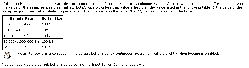
The samplesPerChannel parameter has different features according to the synchronization mode, you choose. If you choose finished samples the parameter samplesPerChannel determines how many sample clocks to generate and also determines the exact size to use. But if you use streaming samples, the samplesPerChannel and speed settings are used together to determine the size of the buffer, according to this excerpt from the reference help C DAQmx:
Note that this buffer is a buffer software host-side. There can be no impact on the material available on the cDAQ-9188 or NI 9235 buffers. These devices each have relatively small equipment pads and their firmware and the Driver NOR-DAQmx driver software transfer data device to automatically host and the most effective way possible. The buffer on the host side then holds the data until you call DAQmx Read or otherwise the input stream of service.
(2) can I read the buffer, let's say, once per second and read all samples stored in it?
Yes. You would achieve this by choosing a DAQmx Read size equal to the inverse of the sampling frequency (during 1 second data) or a multiple of that of the other playback times.
(3) do I have to implement my own buffer for playback of data acquisition, or it is not necessary?
No, you should not need to implement your own stamp. The DAQmx buffer on the host side will contain the data until you call the DAQmx Read function. If you want to read from this buffer less frequently you should consider increasing its size to avoid the overflow of this buffer. Which brings me to your next question...
(4) because I don't want to lose packets: y at - it a timestamp index or a package, I can use to check for this?
DAQmx will meet you if all packets are lost. The default behavior is to stop the flow of data and present an error if the buffer of the side host DAQmx overflows (if, for example, your application does not pick up samples of this buffer at a rate equal or faster than they are acquired, on average).
If, for any reason, you want to let DAQmx to ignore the conditions of saturation (perhaps, for example, if you want to sample continuously at a high rate but want only interested in retrieving the most recent subset of samples), you can use the DAQmxSetReadOverWrite property and set it to DAQmx_Val_OverwriteUnreadSamps.
I hope this helps.
-
High sampling rate for 18 strings in a single task - DAQmx
Hello
My current experiences require the acquisition of 18 channels (6 HAVE custom voltage with excitement, voltage AI 12) data at a sampling frequency of 50 kHz. My question is if it is faesible using a single cDAQ-9172 chassis. Used modules are 2 x NI 9237 and 4 x NI 9215.
The previous researcher on this project used 2 different Renault to do this, but I was hoping that I could reduce it to a single DAQ to simplify the synchronization of all channels.
I wrote a *.vi (attached) to do this and write to a TDMS file using a structure of producer-consumer; However, when I run the * .vi, I can run for minutes, but the number of samples recorded for the PDM is rarely more than 100 k. Subsequently a buffer size error (attempted to read from the samples that have been overwritten) with less than 200 k samples ever record. I checked the max sampling rate (using a property timing node) with the configured task as in the * .vi and it shows a maximum of 235kHz.
I can't say if I make just the structure of the producer consumer incorrectly or if I ask too much of the cDAQ-9172 unique?
Any help would be much appreciated.
See you soon
Bart
Hi bart.s,
TiTou speaks sampling aggregate not simultaneous, so sampling rate 50kS/s is the same for all channels.
I see the problem in the loop of the producer. If your sampling frequency is 50kS/s/ch and you read that a single sample/ch you will lose data because the producer loop cannot run so fast. You should read more than one sample. I recommend you also to move your tracing to the consumption loop code and work with larger amounts of data.
The second problem may be with the error handling in your loop of consumer. Merge the mistakes of loop of consumer and producer and also add a few general for two loops off if the error occurs (for example, using local variable).
Best regards
CaravagGIO
-
Save the high sampling rate data
Hello!
I use NI PXI-4462. (204.8kS, input analog 4 / s sampling frequency)
I want to collect data from "load" (channel 1) and "acceleration sensor" (2nd, 3rd, 4th channel).
I also want to save data to a text file.
So I do a front pannel and block diagram. You can see in the attached file.
The program works well in a low sampling rate.
However, when I put up to 204800 s/s sample rate, the program gives me "error-200279".»
I don't know what means this error, and I know why this happened in the high sampling rate.
I want to know how I can fix it.
Is there any problem in my diagram?
Is it possible to save high sampling rate data?
I really want to samplling more than 200000 s/s rate.
I would appreciate if you can help me.
Thank you.
NH,
You have provided excellent documentation. So what has happened is that the amount of time it takes to run the other portion of the loop results in a number of samples to be taken is greater than the size of the buffer you provided (I don't know exactly what it is, but it will happen at high frequencies of sampling high) resulting in samples are crushed. You might be best served in this case to take a loop of producer-consumer - have the loop you have acquire the data but then have an additional loop that processes the data in parallel with the acquisition. The data would be shipped from the producer to the consumer via a queue. However, a caveat is that, if you have a queue that is infinitely deep and you start to fall behind, you will find at the sampling frequency, you specify that you will begin to use more and more memory. In this case, you will need to find a way to optimise your calculations or allow acquisition with loss.
I hope this helps. Matt
-
Hello
I tried to understand how the 'number of samples' and 'rate' controls affect the frequency of sampling for the DAQ hardware. For example, say I want to acquire data from a sensor of pressure at a frequency of 10 Hz intuitively, I would think everything I do is on the desired sampling frequency, in this case 10 Hz control the 'frequency', try this, I know that's not true. I read that 'number of samples' affects the sample rate by setting a buffer value that must be reached before the VI will process the acquired data. So I also tried to set the "number of samples" to 1 and "rate" at 10, thinking this would have led to a sampling frequency of 10 Hz, and again, it is not. The only way I know to control the sampling frequency is using the wait function (ms), but then I always get buffer overflow errors.
Can somone if you please explain to me the error in my thought process and also tell me the best way to control the sampling frequency? Is attached a simple VI, I am using to measure my actual sample rate and compare it to the sampling frequency that I am trying to achieve.
The VI use the DAQ assistant to acquire data of pressure, inserts data into a table, and measure the size of the array. I'm then by dividing the size of the array by the elapsed time in seconds for the sample/s (I'm also dividing the number of iterations of the loop by seconds and using it as a comparison). I compare this value to my entries for the 'number of samples' and controls 'speed' in order to give a sense of the role they play in sampling rate. The VI also allows to choose to use the wait function (ms), as well, using this function is the only way I can control the actual sampling frequency, but then I always get buffer overflow errors. Any information would be helpful, thanks!
What is the device that you are using? My guess is that whatever you have, it does not allow such a slow pace and is failing at its minimum.
-
Guidelines to set the buffer size?
Are there articles or messages that describe the basic guidelines for choosing the sizes of memory buffer to use when acquiring data?
Are there specific problems that occur when the buffers are too large or too small?
Thank you
Dave
The buffer must be large enough to handle the data acquired during the long interval between reading th book.
Too small and encounter you problems if you do not read your data fast enough.
Too much and you lose memory.
My personal recommendation is "close your eyes and imagine the user trying to open a huge Excel spreadsheet while the application is running" - However for long, I suspect that the PC will have to open the file will dictate (based on the sample rate) what is the minimum size. In the old days, I would just double this figure. These days, I can use a 5 fudge factor.
Ben
-
DAQmxCfgSampClkTiming sampling rate for external sources
I'm looking at the example of Synchronized_AIAO_Shared_Clock.c to http://zone.ni.com/devzone/cda/epd/p/id/2352 . This example creates a string of tension that HAVE streams at 10 kHz, and then creates a tension AO channel that is bound to the sample clock HAVE to synchronize channels. I use this example to understand the use of DAQmxCfgSampClkTiming here. This is the corresponding code (comments are mine):
Create a channel of tension HAVE will work continuously at 10 kHz
DAQmxErrChk (DAQmxCreateTask("",&taskHandleRead));
DAQmxErrChk (DAQmxCreateAIVoltageChan(taskHandleRead,"Dev7/ai1","",DAQmx_Val_Cfg_Default,-10.0,10.0,DAQmx_Val_Volts,NULL));
DAQmxErrChk (DAQmxCfgSampClkTiming(taskHandleRead,"",10000.0,DAQmx_Val_Rising,DAQmx_Val_ContSamps,1000));
Create a tension AO channel, and then attach the clock of the chain in tension of the AO for the sample clock HAVE
DAQmxErrChk (DAQmxCreateTask("",&taskHandleWrite));
DAQmxErrChk (DAQmxCreateAOVoltageChan(taskHandleWrite,"Dev7/ao0","",-10.0,10.0,DAQmx_Val_Volts,NULL));DAQmxErrChk (DAQmxCfgSampClkTiming(taskHandleWrite,"ai/SampleClock",1000.0,DAQmx_Val_Rising,DAQmx_Val_ContSamps,1000));
.. So what I'm trying to understand here is how to interpret (1000.0) sampling rate argument in the second call to DAQmxCfgSampClkTiming, where the canal AO is related to "AI/sampleClock. It seems to me that this argument must be meaningless, other than perhaps to determine the size of the buffer, since by definition this AO channel will clock on a sample of every time that AI/SampleClock rises. Then maybe someone can help me understand how this argument is used...
But in all cases, the docs say "If you use an external source for the sample clock, set this value to the maximum expected rate of the clock." In this case, the clock is set up a few lines earlier at 10 kHz, so is not this 'evil' in the second call to DAQmxCfgSampClkTiming, a sampling rate of 1 kHz is specified (much less than the maximum rate of sample expected)? What is the consequence of this?
Thank you!
-Dan
Hey Dan, some big questions you've got.
You pretty much put the nail on the head with your guesses. The size of the buffer is based on the resolution of data acquisition in combination with the sampling frequency that you specify. Think of it as an implicit in the size of the buffer declaration (but it is certainly an explicitly define that, if you wish).
As for your second question, which relates to new back to the size of the buffer, except that this time it is for the use of an external clock source. Given that the material has no implicit way to know the frequency of clock of this external source, it asks you to specify explicitly the maximum frequency so it can create a buffer of the right scale size.
-
So maybe this is a stupid question, but I need to know because I train for a specific sound. Is there a way [to logic] to shoot/change of a certain frequency sampling rates. I can imitate the sound I'm looking for with a low pass filter, reverb and a distortion. But I don't want to 'emulate', this sound, I want to create. Then I can put my own effects and play with it like I want to. If I have to use a bunch of effects to make it sound like I want that also the addition of said effects remove the sound and sound horrible. as to where pulling the sampling frequency of the high frequency and no downs will make me THE noise that I need and always allow to add nice effects to make MY sound instead of someone else. I hope you know what I mean. Let me to you specific real once more. I want to pull or carry a certain frequency sampling rates for a sound under water. I don't want to use filters to make the sound. So can you please help me. I invited everyone locally on how to do it and nothing works. Also if this is not possible in the logic of tell me if there are third party plug ins or maybe even a different DAW that could do like komplete Kontrol or audacity.
See if this thread is helpful at all...

Maybe you are looking for
-
Auto answer on 7.0.85.102 problem
With the last update (7.0.85.102) calls to my office if self answered even if the auto answer option is disabled. This means that callers cannot leave a message and that unwanted calls are turned on, even if I don't accept them at this time. My syste
-
OfficeJet Pro 8620: Officejet Pro 8620 again in large printing green instead of yellow
HP have a simple messaging as the online chat service closed when I go home and woanting to know if there is a simple solution to get the correct color as printer doesn't have a clean-up and his only 10mths old Thank you Joffa72
-
Printer prints only 3/4, last part of the page is faded.
Whenever I have the impression that part of the page prints part background fades.
-
Cannot install service Pack2 dllcache copy
Recently reformatted my computer with a new copy of windows XP home. After update service pack 2 during its installation, I get hundreds of reviews saying "cannot copy the abcdefg.dll file to ensure that the location below is correct, or change it an
-
How the eyes it save to my name
Eye just got a used computer with win xp, now how the eyes register in my name