Build tables then again
Hi all
I know that you are reading these words a lot here, sorry, I'm new to labview and I want someone to help me in vi that I'll explain now.
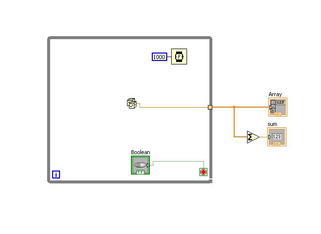
I have a while loop with a variable inside (local variable or a random variable in this example), the loop has timeout of 1000 ms, so each one second there is a new value.
After a time, I want to record what the output variable into an array and then summarize all these values and then display.
I trigger the recording process manually by using a Boolean trigger, so, no need for a timer or something, I have you just press a button then values begin at accomulate in the table and then when I release the button, I want these values to summarize and display, then I have another RESET Boolean, I press reset the values of the transom zeros in order to press the key once more again later in and then the process is repeated again.
I did the vi in the way I write now that I can start only the vi so the values accomulate and then when I press the Boolean value affects the loop stops and then the table is summed up and display.
the problem is that I can not reset the values or repeat once again because when I press the Boolean value, stop the loop and I cannot start over once again.
I'll be very grateful if someone helped me with that.
Thanks in advance
Concerning
Shady
Hey shady,
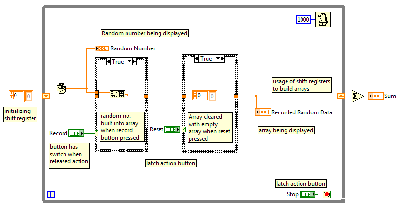
It is always advisable to use the registry to offset for building tables. Using a while loop within a Structure of matter is not a good programming practice. Check out the attached VI. This should help you.
Best regards,
NitZ
(Bravo to give good answers, mark it as a Solution If your problem is resolved )
)
Tags: NI Software
Similar Questions
-
Permanently add values in a table then VI run
I currently have a situtaion where I get a number of numerical values on a single line I need to store in a table. This has to be done during the execution of the program. I know that I can use the 'Build table function' but the word really sure I'd need some time loop with shift registers or a feedback node. Any suggestions on what would be the best way to implement this?
After some people on this forum have done test (because they had the same question),
The shift register is about 4 times faster than that of the feedback node.
But in terms of functionality, they are identical. -
computer restored IBM won't let me go beyond the introduction of identy... closes and restarts the computer to the same: Enter name and ID... then again, it does the same thing. How can I save this monster?
Hello
First, disconnect all the external devices connected to the computer, and then try to start and check what is happening. If the same happens, then you can try to start in safe mode and check if you are able to boot to the desktop. Only basic files and drivers needed to run Windows are started. If a problem doesn't reappear when you start in safe mode, you can eliminate the default settings and basic as possible cause device drivers. To start in safe mode follow the link.
Start your computer in safe mode
http://Windows.Microsoft.com/en-us/Windows-Vista/start-your-computer-in-safe-mode
Hope this information is useful.
Amrita M
Microsoft Answers Support Engineer
Visit our Microsoft answers feedback Forum and let us know what you think. -
I ve tried to get the windows icon 10 but it goes up to 99% and then again never getting to 100%
* Original title: updates-windows7 professional and windows 10.
I installed windows 7 Professional on my pc. ASUS x54c but now I can not get more automatic updates. Ive also tried to get windows 10 icon but it goes up to 99% and then again never getting to 100%, I tried everything I see no chance. can someone help me.
If the Upgrade Wizard of Windows 10 becomes blocked or unresponsive to 99%, wait at least 4 to 7 hours. If the installation program does not progress, close the wizard and restart your computer. Follow the instructions to upgrade manually by using the tool of creation of media or file ISO for Windows 10.
If you encounter an error about enough space to perform the upgrade, see the instructions:
How to install Windows 10 on devices with limited space
Task of pre-required
When you make significant changes to your computer for example updated operating system, you must always back up. See the links to resources on the backup by clicking the link for each version of Windows you are using: Windows XP, Windows Vista, Windows 7, Windows 8/8.1
- How to: 10 tips before installing Windows 10
- How to: 10 things to do if the Windows 10 install fails.
Retry the upgrade manually:
Option 1: Using the media creation tool
Download the media creation tool
Click with the right button on the MediaCreationTool.exe file and then click on run as administrator.
Note: How to check if you are downloaded or installed the update Windows 10 November
Select upgrade this PC now and then click Next
Option 2: upgrade using the file ISO for Windows 10.
Task of pre-required
When you make significant changes to your computer for example updated operating system, you must always back up. See the links to resources on the backup by clicking the link for each version of Windows you are using: Windows XP, Windows Vista, Windows 7, Windows 8/8.1
- How to back up and restore your files manually
- How to free up disk space in Windows
- How to: 10 tips before installing Windows 10
then
- How to download official Windows 10 ISO files
- How to: upgrade previous versions of Windows using the file ISO for Windows 10
then
- Turn off (preferably uninstall) your Antivirus utility before you perform the upgrade.
- Reboot several times, and then try again.
- Disable the general USB peripherals (for example - smart card reader). You can do so from the Device Manager.
- If you have an external equipment, attached to the machine, unplug them (example, game controllers, USB sticks, external hard drive, printers, peripherals not essential).
- Support your default BIOS reset BIOS.
- Check if there BIOS updates available for your system, and then to apply them.
- If you are using a SCSI drive, make sure you have the drivers available for your storage on a USB device and it is connected. During the installation of Windows 10, click on the advanced custom Option and use the command load driver to load the driver for the SCSI drive. If this does not work and the installer still fails, consider switching to an IDE based hard drive.
- Perform a clean boot, restart, and then try again.
- If you upgrade to the. ISO file, disconnect from the Internet during the installation, if you are connected in LAN (Ethernet) or wireless, disable both, then try to install.
- If you are updated through Windows Update, when download reaches 100% disconnect from the LAN (Ethernet) Internet or Wi - Fi, then proceed with the installation.
- If this does not work, try using the. ISO file to upgrade if possible.
- If you are connected to a domain, go to a local account.
-
Mr President
If I have the two LOV in the same table then how to connect when I select first and second LOV value also change?
My two fields are FLOW AND DR_NAME
FLOW = ACCT_ID
DR_NAME = ACCT_NAME
I created with success of LOV for these fields.
First LOV gives acct_id in the debit field and second LOV gives the value of acct_name to dr_name.
How can I report these lov, it's that when I change my acct_id then acct_name also change
I have these two tables
CREATE TABLE "NOM"  (
  "ACCT_ID" VARCHAR2(7) NOT NULL ENABLE,
  "ACCT_NAME" VARCHAR2(50) NOT NULL ENABLE,
  "O_BAL" NUMBER(13,2),
  CONSTRAINT NOM_PK PRIMARY KEY ("ACCT_ID")ENABLE

   );
CREATE TABLE "VOUCHERDET" (
  "V_ID" VARCHAR2(9) NOT NULL ENABLE,
  "LINEITEM" NUMBER ,
  "DEBIT" VARCHAR2(7) ,
  "DR_NAME" VARCHAR2(50),
  "CREDIT" VARCHAR2(7) ,
  "CR_NAME" VARCHAR2(50),
  "PARTICULARS" VARCHAR2(100),
  "AMOUNT" NUMBER(21,2),
CONSTRAINT VOUCHERDET_PK PRIMARY KEY ("V_ID","LINEITEM")ENABLE,
CONSTRAINT PUR_SAL_LINE_POD_FK FOREIGN KEY(PROD_ID)
  REFERENCES PRODUCTS (PROD_ID)ENABLE,
CONSTRAINT VOUCHERDET_DEBIT_FK FOREIGN KEY ("DEBIT")
   REFERENCES "NOM" ("ACCT_ID") ENABLE,
CONSTRAINT VOUCHERDET_CREDIT_FK FOREIGN KEY ("CREDIT")
   REFERENCES "NOM" ("ACCT_ID") ENABLE,
CONSTRAINT VOUCHERDET_V_FK FOREIGN KEY ("V_ID")
   REFERENCES "VOUCHER" ("V_ID") ON DELETE CASCADE ENABLE
  );
Concerning
so, instead of this second ActId, choose ACCT_NAME:

-
Mr President.
Is it possible that when the new record is inserted in a table then this empty inserted record is automatically displayed without scrolling?
Because I change the size property of the table 5 range and my new record is inserted at no 10.
When I click the addRecord button the new parallel line does not appear, do scroll down to see it.
I want that we don't have to scroll down.
The line is displayed automatically.
as shown in the photo my behavior of page.

Concerning
If you just need the newly created line to be visible,
You can simply set contentDelivery = 'immediate' and displayRow = "selected".
P.S. the blog mentioned above only.
See you soon
AJ
-
Build table 2D-the only condition of case string
Hello
I'm having a problem when I am trying to build a 2D of the elements of the string table. Here's basically what I'm doing:
I'm loading the tables in different text files (Session_001.txt, Session_002.txt, etc.) and concatenate into 1 big table.
On each line of text Session files, there is the session number, various characteristics of hockey sticks, and then a couple results.
I want to be able to select the various features and then display the corresponding results. Currently, I'm working on the selection of the Session, and when I get this working, the rest would be similar (I guess).
The problem I have is that when I select the sessions that I want, the Array3 resulting (with all data) is filled with empty lines (table 1 d of the empty elements). I had the same problem when display a table 1 d (table 2) coming to show what Sessions had been selected, but I managed to fix that by searching for and deleting empty elements.
The problem lies within the structure of matter I. I compare all the elements in the first column of my huge 2D array with each number of the selected Session, and when it is 'true', that I keep the current line to go to table 3. If it is "false", nothing should happen (I have a registry change through my case 'false', but a line of empty strings is added to the table.
What Miss me?
I know this probably sounds very confusing, so I join you the only VI and a zip containing the VI and my text files.
Thank you!
Off topic (Finally, still on the topic of my VI), it will be possible to assign a different color for each type of stick (MX3, APX3) or the different type of marker for different types of shots (WS, SS), etc., when I want to display the results on the same graph? If not, stop now and I'm going to Matlab.
Oh my... Equal to true. I'm so ashamed.
I just started Labview on my internship 2 weeks ago. There are probably several simplifications I can do for my screws, but as long as they work and do not burn my laptop, I agree.
With respect to the conditional tunnel, I n, t really know to use it yet, but I found the problem with my registry to offset. I created a 2D array empty outside the two loops and added a registry to offset. I then build I tried to rely on another thread.
Resolved VI is attached to anyone who cares

-
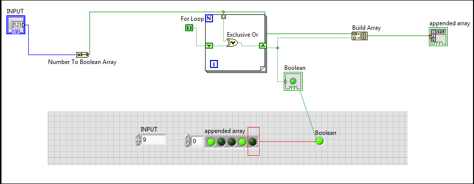
I am struggling to determine why the value of the only Boolean value below isn't concatinated to the arrary annexed table build?
I understand that it isn't an arrary but a shift register value. But surely I can use this value T/F and added it to the array version some how. Please advise I think I'm going crazy: manembarrassed:
You always have a point of stress on Indicator0001. As you now convert a U8 in an array of Boolean, but indicator 0001 shows only 4 elements. It is safe for me to think that your meter is somehow an array of fixed size?
I would avoid using a fixed table data type. If you want to only 4 items in table 8 original item, then use Array subset to get only the items you want. Then all your calculations later works and is displayed correctly.
-
Dynamic data of several channels in table, then save in Excel
Hello
I am acquiring data from several channels (4-5) and I'd like to collect samples at low rates (10 Hz for 3 minutes max). For various reasons I use Dynamic Data type, although I know that it is not the best way (some say it is a wrong data type
). I also want to save data to a file (the best option would be data excel file).If I acquire data 10 times per second, it is quite slow to save in excel (this is the slowest option of all types of data). So I would like to fill a table or matrix of acquired data and then write Excel file (I use scripture to measure file). But I don't know how to do - if I convert DDT in DBL, build an array and connect it to change registry, it works but I lose the information in column names and I'm wasting time. If I connect to build the table a DDT and then shift record another, it returns the table 1 d of DDT. I would like to have 2D DDT, which collects all the information loop. Is there a suggestion how to solve?
I'm sure it would be easier solved my problem with the double data type but I also use select signals VI which is the VI I am not able to replace at this time.
Good day
Lefebvre
I don't know if there is a question here, or what. Doing what you say you want to make, acquire the data of 4-5 channels at low rates (10 Hz for 3 minutes) and save the data in an Excel file (I assume you mean really Excel, i.e. a file with the extension .xls or .xlsx) is really a very easy thing to do in LabVIEW, especially if you are not using :
- DAQ Assistant
- Dynamic Data
- Write to the action file.
Indeed, you seem to realize this, but I guess you want to 'do the hard', in any case.
Good luck.
Bob Schor
-
Build table retaining memory between executions
Hey everybody,
I'm relatively new to LabVIEW and try to design an executable to read the measurements of a digital multimeter that takes measures and integrate them into a table which then transfers to an Excel document.
I received the DMM upward and running, I have got to write to the file, but if I run several times he tries to build the file using past performance and the results of the current test.
How can I empty the system memory so that it starts fresh every time?
Right now I use a loop which refreshes the numerical measures and use buildarrays to compile all of the results (shift registers to sell berries). At the end of the code (stop button) they transfer to be compiled into tables.
Hi anthony,.
I have attached the VI the problem of shift register. When you run that a vi with SHIFT registers him registry will remain in memory until you close. Then, when you run your first iteration, it will start by default, then stop. When you restart it without closing the register shift will keep the values from the previous run. As long as the temperature outside the loop so you reset the registry of each race.
-
Hi guys
Need some help here
My goal is more
1. create a table based on the values programitlitly beeing past in the table
2. This should each time when a Boolean value is true.
3. the table building function should wait 6 s when the value is true before you store them in the array
My problem is that when I press on True and begin to change the value to the value desired before past 6 seconds, the value passed to the table after 6 seconds is the starting value before I changed to the desired value betwwen 1 to 6 seconds.
It drives me crazy
And the desired value must come within a structure of sequense
The attached value se
Put the digital terminal in the second image in the sequence. In this way he'll only get read after 6 seconds.
-
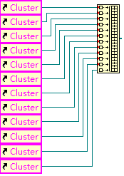
Build table - you have connected two terminals of different types
Hello, I'm getting my vibration sensor data using my USB 9171 cdaq and the NI 9234. I want to display the signal of vibration, to record in a file, to do all kinds of possible statistics and the display of the statistics table on the front in update mode, attached is my VI based on some examples in the finder of the example, it has an error, can someone help me to make it work. Thank you very much in advance for your collaboration. Ihab
Change the table build to add entries instead of concatenate.
Lynn
-
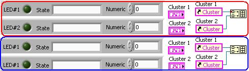
Why "arrow red triangle" show in build table function?
refer to title, when you use the function 'building the table' why it displays "arrow red triangle" in the port of entry, you can see two photo below, why this difference occurs?
any response is high appreciated!
I got the reason: even the label of controls must be identical.
-
LabVIEW fpga compile: translation error then again translate
Hello everyone,
I have a question about the process of compiling LV FPGA.
The context:
I am compiling a binary FPGA for the NOR-5644R (viterx6 inisde). the process is quite long (up to 7 hours depending on how is our CLIP). I am canvassing any idea of attaching the compilation process.
The fact:
By analyzing the log file of the previous compilation, I noticed that the stage translate is made twice, probably because one is a failure. the excerpt from log files are copy/paste below.
Further, it seems the errors (at least some of them) translate the first are induced by the commented lines of NOR provided file UCF (RfRioFpga.ucf)
The question:
Why to translate step to do it twice (the first being failed)? would it not quicker to make only the second succefull one? in other words, it is really necessary for the first fails to translate step for the FPGA binay?
Any ideas?
Thanks in advance!
See you soon,.
Patrice
----
log file extract 1:
"...
NGDBUILD Design summary of results:
Error number: 387
Number of warnings: 1443Total in time REAL until the end of the NGDBUILD: 2 h 16 min 45 s
Time CPU until total NGDBUILD: 2 h 11 min 21 secOne or more errors were found during the NGDBUILD. No file NGD will be written.
Writing the file of log NGDBUILD 'RfRioFpga.bld '...
'Translate' process failed
..."
log file excerpt 2:
"...
NGDBUILD Design summary of results:
Number of errors: 0
Number of warnings: 818Writing the file 'RfRioFpga.ngd '... NGD
Total in time REAL until the end of the NGDBUILD: 29 min 17sec
Time CPU until total NGDBUILD: 27 min 33secWriting the file of log NGDBUILD 'RfRioFpga.bld '...
NGDBUILD done.
'Translate' process completed successfully
..."
Hi Patrice,
It seems strange that it performs this step two times (and was worried when I saw the first time), but there is good reason for that, certainly. LabVIEW inserts constraints for components, he adds, but sometimes the components get optimized out by the compiler. When the compiler encounters stressed that points to the now non-existent component, it error. LabVIEW circumvents this by running the process to translate two times. The first time, it may fail. LabVIEW will remove the constraints that fail, then run again translate it. Unfortunately there is no way around this problem.
-
Build table experimental Points on
What I do with labview, use an output module for the control of a valve ball valve and finally flow rate throug a pipe. I'm trying to set up a loop that will gradually open the valve and at each stop point account made the position of the valve and the flow rate (flow of a counter with output 4-20). Then using the data table, I should be able to draw line inbetween each pair of points and use my line segments to define the flow curve.
Then in operation I should be able to ask for a flow, and using the initialization data, labview can send the signal to the right position to the valve.
I'm stuck on the construction of this picture however. In addition, at this stage I am simulating signals, positions and rates based on some arbitrary relationships.
For now I would record the points on the Board based on the click of a button. In you future I have will automate.


Maybe you are looking for
-
Google won't let me not on Google + until I update (which I have, twice), but more surprising, FF insists that I need to improve (I'm under 3.5.1 claims!
-
Satellite L850-1V0 - module cooling fan runs constantly at the same volume
I've had this laptop since the middle of February this year. I experienced a few problems I am getting concerned: The first is my fan, regardless of how high the percentage of my CPU temperature is that it will always show that the fan works at a spe
-
It might be a good idea to let people know, when they start doing their custom Moto X, the 32 GB model is not available. I spent a lot of time (because I was too picky on colours) seeks to know if there was any color in which the 32 GB of the Moto X
-
Safari does not display the images (looked for fix, tried many things, can't find one that works)
Hello My safari will display all the images, for example Google Logo, image profile of everyone here and much more. So I was wondering how I can fix this problem? Either way, I have 3 accounts on my computer, works on the other two, but not mine. Tha
-
Compatibility issues with VB 2005, VB 6.0, SQL 2005
Whenever I try to install the 3 above s/w on my system it shows compaibility problems with windows. Please suggest me is there any solution to deal with. OS: Windows Vista Home Basic X 86 N advance thanks