Butterworth amplitude
I generates a white noise of an amplitude of 100. Then I go through a Butterworth bandpass filter with 50 and 150 for the high and low frequency bandpass settings. I find myself with a noise filtered with an amplitude of 20 (more or less).
Why the filter reduces the amplitude of the filtered noise? I noticed that if I increase the range of bandpass parameters (for example, 50 to 500), amplitude reduction is a little less.
I tried other filters and Chebychev seems to be a little better, but it does still not anywhere close to the amplitude of the original signal.
I admit that my knowledge of signal processing is limited. Can someone help me with this problem? Is there a setting that will give me the best results?
Thanks for your replies.
I was under the impression that white noise with an amplitude of 10 when it is passed through a filter would result in filtered amplitude noise 10. But now I see why I was wrong. White noise is the sum of the sine waves of different frequencies; for example, when you filter on certain frequencies, amplitude (which is a sum) will be lower.
And thanks for the tips on the standardization of the amplitude after filtering. That's what I'll do.
David
Tags: NI Software
Similar Questions
-
Amplitude varying on the change of the input frequency
Hello
I using NOR-5752 scanner to measure the analog inputs of high frequency. NOR-5752 is connected to the module FLEX RIO 7966R and entry to the NOR-5752 is provided using the SMB-2145 terminal outlet box.
Now, I'm the animals the 0.5Vpp @ different frequencies of tektronix generator of functions directly and by measuring using the digitizer. On the change of the frequency, measured amplitude is changed.
All,
For the NI 5752 frequency response strange behavior is expected. CDA in NI 5752 is the TI AFE5801 (http://www.ti.com/lit/ds/slos591d/slos591d.pdf), and if you look at Figure 19 (p.13), you will see that frequency response of the ADC is only flat after about 1 Mhz. I checked this with our R & D Department and they said they are not aware of any combination of parameters that gives a uniform frequency response at these low frequencies.
If a flat frequency response is necessary for these lower frequency ranges, then the 5751 NOR is much better suited because it has a different ADC. (http://www.ni.com/pdf/manuals/375602b.pdf) The frequency response of this device is very flat in the low frequencies (see Figure 11 p.15).
So both devices, NI 5752 and the 5751 OR are designed to measure different frequency ranges. I hope this helps.
-
FGEN 5402 Amplitude at low frequencies
Hello
Sorry, I don't know the right place...
I work with the NOR-PXI-5402 FGEN.
My measurement is 1000 Hz to 1 Hz. The amplitude of my example is 1V.
The FGEN made 1000-15 Hz 1V. After 15 Hz amplitude will made to 700mV (10 Hz), 500mV (5 Hz) so on.
Is this normal behavior?
How can I set the voltage at 1V constantly?
I work with Labview, by the way.
Thank you!
Turn off AC coupling on the scope. The cut of the 5105 is 12.
http://www.NI.com/PDF/manuals/374403b.PDF#page=4
Jason L
-
How to display wav on a table or chart, if the user enters frequency, amplitude, shape, offset
Hello
I have a program (an example of program) where the user can enter the frequency, amplitude, shape as well as the compensation of a wave. How to take these properties and in the wiring diagram to display the waveform on the front panel (in a table or a graph)?
Frequency, amplitude and offset is a double. Waveform in the wave function of type.
code attached.
Please answer. Thank you.
To see the actual waveform, you obviously have another instrument connected to the output of the Agilent. If you want something simulated as closely as possible, you can wire the wave to a case statement function and set a function of generation of waveform appropriate inside each case.
Edit - you also posted to the wrong Board. In the future, don't forget to post on the instrument (approximately Agilent) control or Council of LabVIEW (regarding the functions of generation of waveform).
-
How to set the amplitude to pwm full example?
Successfully, I downloaded and ran the program in example shown here:
http://www.NI.com/white-paper/2991/en
and see the pulse train to build into my oscilloscope. When measuring the value of a strong impetus, the oscilloscope said 5V.
How can I change to 3?
Watching the DAQ Create Channel node I see any inputs for the amplitude, only the frequency and duty cycle.
Which is set the amplitude to 5volts, and how can I change it to 3V?
Very similar. On the icons above the text box 5 step, you must right-click on the appropriate terminals to add controls for the Offset and the duty cycle.
Calendar/generation is made via the material in this case.
-AK2DM
-
Why Express PSD gives a different result of amplitude as FFT PSD?
Hello
When I use the express VI of spectral measures to trace the power spectral density, I get a different result than when using the FFT PSD VI. The data are the same but the amplitudes are different in the PSD plot. Everyone comes through this?
Thank you
Donners,
The PSD2 and graphic PSD2 are different because you are breastfeeding two extra points in the tables (t0, df). When graphic entry of data in the tables, they interpret not automatically information of t0 and df. Actually they do not yet receive this information. You must program the scales with nodes of property. If you simply draw the order of magnitude, the spectra are very similar.
^ ^ ^ This confuses only the chart!
The spectral forms differ slightly as the power spectrum of FFT and PSD.vi uses a default Hanning window.
Lynn
-
How to configure the amplitude on the CLK OUT coming of the NI PXI-6652?
In the document specification NI PXI-6652, it clearly says under CLK features OUT of this magnitude ", Software Configurable. But I couldn't figure out where I can do? I'm going to CLkOUT 1Vp - p. I want to program to 2.5 VDC.
Ashok
Hi Solanki-
The amplitude of the CLKOUT signal is selectable by software between two levels. Under a 50 ohm load, you can change the amplitude of 1 p to 2.5 V p Pei Pei V using a niSync property node. This can be found in LabVIEW under the palette of NOR-SYNC. Place the property node down and click on the word "Property". Select Properties Clk» Clk Out Gain Enable. Then right-click on the property node, and then select "Change while writing." Then right-click on the entrance to the property and select Create' constant. The constant change True and your CLKOUT will be high.
I hope this helps. Good luck with your application!
-
Calculate the peak-to-Peak Amplitude
I wonder if it is possible to calculate the amplitude peak to peak of a sine wave. I have a waveform of a proximeter for a period of ten seconds and would like to calculate the amplitude peak to peak for each cycle.
The DIAdem analysis window has a peak/Valley feature that will allow you to find the peaks and valleys of a signal. Depending on the exact service you use, you can either keep those results as a 'results chain' or a new property of the wave. Whatever it is, once you have found the peaks and valleys, you can add the pic to the absolute value of the value to find the full peak-to-peak amplitude.
If you need to do this in an automated way, you can write a script fast enough to call these functions programmatically.
-
Generation of amplitude modulation and frequency modulation
How to generate AM and FM using simulate block signalling.
This is not possible with just the simulate signal vi express. You'll need to generate a signal by using this vi and then make your own amplitude and/or frequency of the generated signal modulation.
-
Hello
We thought to use a map of PXI-5421 arbitrary signal generator to generate a signal of 'light at the top' 50 Hz, but the maximum amplitude of the signal must be +/-14V but available from the 5421 maximum amplitude is +/-6V, ideas?
Concerning
Steve
Yes. You will get (27 000 / (27 000 + 50)) = 99.815% of the tension in your load, or +/-11.978 V.
Neil
-
What is the GPIB for mitigation of amplitude Spectrum Analyzer?
Hello
I write a test automation, and I need to do the following by programming GPIB:
Press on AMPLITUDE balance, mitigation, 0, dB.
The device is Agilent E4407B spectum analyser.
I searched on the internet and made searches and cannot find the GPIB string that mitigation of the amplitude of programming orders.
(I found all other controls that I need for this Automation).
Actually, the test plan I put in work in the programming, said that it is no longer available via the keyboard input.
Could it be? All keyboard commands have corresponding GPIB commands outside of it? Why?
Maybe it's because the same effect can be achieved by a different order of GPIB? What is it then?
Thank you!
Tova
-
Amplitude measurement of a continuous signal in a given time window
I'm working on an acquisition system that acquires a continuous signal of 250 kHz. My goal is to measure the amplitude peak-peak of the first reaction of signal, the problem with my setup, this is the first part of the signal is always higher than the part of the signal that I'm interested. If I try to use the measure of max from Ridge to ridge of signal VI then responds with the measure of Ridge Crest of the initial part of the signal. See the attachment for a better understanding, I would still like to view the raw signal as is, but I would like to measure the peak voltage at peak of the signal between the yellow sliders.
Thanks in advance...
If transient initial always occurs in the first 12 microseconds, you can use any subset of table or similar wave function to retrieve the last part of the wave. Then use the measurement from Ridge to Ridge on this subset.
Lynn
-
I am creating a style for an old scanner (DC240) amplitude oscilliscope interface. Since it is an old system of MXI - 3, the only way I could connect it is by the amplitude PCI compact Crate (cc108) with controller MXI-3 (XC100) to a PXI-8335 with MXI-3 fitting in a PXI system OR managed by an on-board controller Garland (PXI-8104 running Windows XP). Because this Fund is not OR (and does not have a chassis.ini file anywhere where I can find driver, program files, etc.), MAX does not recognize the chassis, it displays simply as 'unidentified chassis' and therefore does not display the digitizer itself as a device. The digitizer is certainly connected, however, because in a non-LabView software program that came with the scanner, it does not work properly.
With this hardware configuration, I'm trying to run some pre-made LabView VI, which initializes the scanners, but they crash or can not find the digitizer. The initialize function is supposed to return an int "intrsumentID", but simply display an error message. Would it not be possible to write my own initialize VI who finds the digitizer and returns this ID? I wish I could describe in more detail what is the funciton initialize pre-made, but uses just a "call library function node" to call a DLL file that I can't access.
I don't know the serial number and the PCI/location of bus of the digitizer hardware ID, but to enter this information into the pre-made VI (he supposedly can read the PCI info or the serial number string to locate the digitizer) does not work. Any help/suggestions would be appreciated.
I was acutally could get it running using the wizard of the Driver NI-VISA and upward! I had problems with this at first because I could not find all the necessary information in the documentation of my instrument, but it was all contained in the Instance ID of the device in Device Manager, that I found here: http://www.home.agilent.com/agilent/editorial.jspx?cc=US&lc=eng&ckey=2039700&nid=-11143.0.00&id=2039....
I thought trying to connect directly as you suggested, but I think my digitizer cards are double the height of the NI PXI chassis, so I could connect the PXI cards in my crate amplitude but not vice versa.
Thanks for the help! The suggestion of VISA definitely showed me in the right direction.
-
Sweep the sinusoidal Amplitude reduction
Hi all.
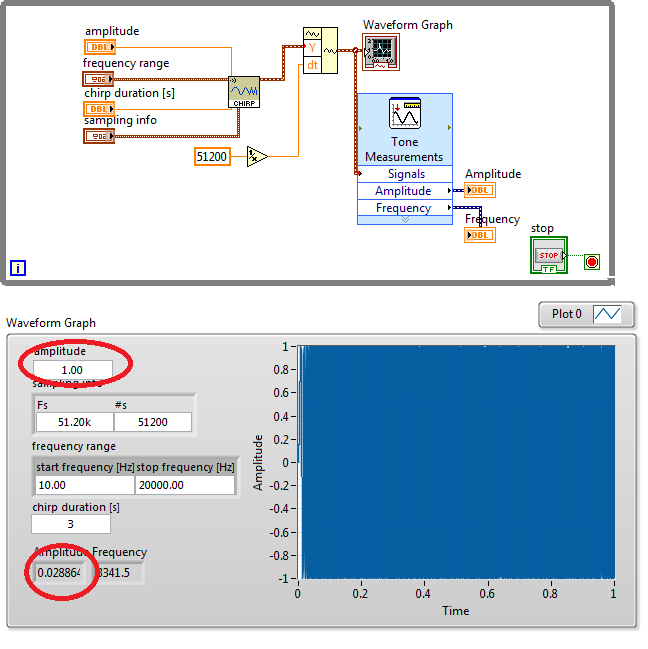
Why is the amplitude of my Sine Sweep decreases?
I wonder why increase my number of samples, which is located in my VI 51200 value samples, the results of my scan to reduce sinus output amplitude. However if my number of samples is small, let's say 1000 samples, the amplitude of output of the VI measures tone is similar to that which is 0.968709.
How can I adjust in order to have the correct value of the amplitude. I have need of the amplitude to be exactly one, because I will be out this in my DAQ.
Here's my VI.
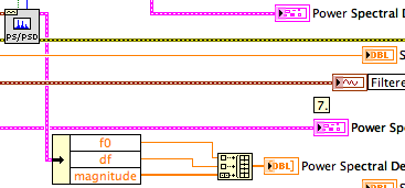
The use of your Measurements.vi is largely meaningless. Read the help for VI. He finds the frequencies where the amplitude is the most important. It uses Fourier transform techniques to find this frequency. Ideally, a chirp Fourier transformation is a constant. Because the real chirp does not cover an infinite frequency and for an infinite time, the spectrum is modified by the effective window. Thus, the peak of the spectrum is approximately in the center of the bandwidth.
Delete a spectral measure VI on the block diagram and draw the spectrum.
When I extracted a subset of table chirp and feed to your measures I have much more reasonable values. Subset starting at index sample 15000 and having length 50 samples returns = 5876.21 frequency and amplitude = 0.99999. The chart shows approximately 5 3/4 cycles in about 1 ms, which is consistent with the measured frequency.
Lynn
-
Bad results value amplitude and phase
I try to add two Phasers of tension and to get incorrect when simulated results on Multisim using the frequency unique AC analysis. I changed the amplitudes of analysis AC from both sources to their respective values of 20 and 15 volts. The result of the addition should be size = 25 volts peak and phase = 66.87 degrees, which does not match results of Multisim. What I am doing wrong?
Thank you in advance.
You must click twice on the fickle source V1 and V2 and the "AC size' and the 'magnitude of AC Phase', change the settings.
Also, depending on your preference, select Options of Simulation global preference, time = 0 if you want the right to shift to change phase or left, you can configure it here. This setting affects your calculation of phase.
Maybe you are looking for
-
Tecra A2: WDDM, LDDM display driver for Windows Vista
I searched various sites for an AeroGlas compatible display driver for my Tecra A2. I ' v have not found anything on the Intel and Toshiba sites. Is there a chance for such a driver? Thank you SincerelyStefan
-
Photo Gallery Windows will be not to save photos - I get error 0 x 80070013
Original title: Edit photo When I try to save my pictures in Windows Photo Gallery, they won't save - I get error 0 x 80070013
-
Cannot display the speaker or the internet on the toolbar icon
system does not allow me to check the speaker volume icons or internet for display on the toolbar
-
I lost the ability to duplex print, after installing Windows 10 and pilots it is advisable for this printer and the HP operating system. Suggestions to get this back?
-
How to place an order in the sccm task sequence to reset the bios on computers laptops hp
SCCM 2007 I'm looking for a command to run in the task sequence to reset the default bios before running the deployment of the operating system 2540 P - laptops HP ELITEBOOK 2560p, 8460p 2570p,.