Sweep the sinusoidal Amplitude reduction
Hi all.
Why is the amplitude of my Sine Sweep decreases?
I wonder why increase my number of samples, which is located in my VI 51200 value samples, the results of my scan to reduce sinus output amplitude. However if my number of samples is small, let's say 1000 samples, the amplitude of output of the VI measures tone is similar to that which is 0.968709.
How can I adjust in order to have the correct value of the amplitude. I have need of the amplitude to be exactly one, because I will be out this in my DAQ.
Here's my VI.
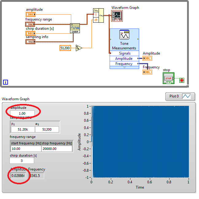
The use of your Measurements.vi is largely meaningless. Read the help for VI. He finds the frequencies where the amplitude is the most important. It uses Fourier transform techniques to find this frequency. Ideally, a chirp Fourier transformation is a constant. Because the real chirp does not cover an infinite frequency and for an infinite time, the spectrum is modified by the effective window. Thus, the peak of the spectrum is approximately in the center of the bandwidth.
Delete a spectral measure VI on the block diagram and draw the spectrum.
When I extracted a subset of table chirp and feed to your measures I have much more reasonable values. Subset starting at index sample 15000 and having length 50 samples returns = 5876.21 frequency and amplitude = 0.99999. The chart shows approximately 5 3/4 cycles in about 1 ms, which is consistent with the measured frequency.
Lynn
Tags: NI Software
Similar Questions
-
[FPGA] Problem with the sinusoidal signal generator
Hello!
At first I want to apologize for my English is not my mother tongue.
Hardware and software I use is:
LabVIEW 8.5
NEITHER RIO 2.4.1
NEITHER cRIO-9014 (controller in time real CompactRIO)
NEITHER cRIO-9104 (chassis and FPGA)
NEITHER 9264 (16 channels, +-10V, 16-bit voltage analogue output Module)
I made a very simple FPGA VI: a while loop, generator of sinusoidal signal and a FPGA of e/s node in the loop. I've specified the Gnerator settings by following the path:
Frequency = 50 Hz
Amplitude = 1
Phase shift = 0.00
Size of the table look-up = 1024
= 16-bit amplitude resolutionFPGA clock frequency (40 MHz)
But the wave of "sine" I got is not what I wanted to get. First of all, its amplitude is 1 V. shouldn't it be coded on 16 bits? If I wanted to get 1V I should have specified Amplitude as a 3277. In addition, 'sine' is not very detailed, it's look like "steps", as many samples vere missing. What I did wrong? I checked the samples and tutorials, I did everything the same way. A I forgot something or not has not specify other parameters?
Thanks a lot for your help!
OK, I solved a problem. It's embarrassing to admit, but maybe this will help someone else
 I blame my inexperience
The main solution to the problem was changing calibration of calibrated RAW Mode. After that, everythoing works as expected. I had a problem with a sample because I was using a multiplier to control the generated sine wave amplitude. But... She was set to 1 in the sinusoidal signal generator. That was the reason for waveform Gradin. Please, don't laugh too much

In any case, thank you for an answer! It is now resolved
-
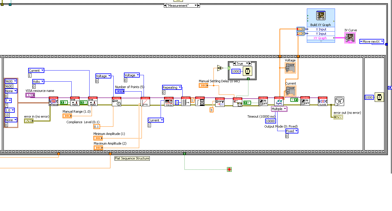
sweep the voltage keithley 2400
Hi friends,
I ve made a small program (reusing an I found in the web) to generate a curve using Keithley 2400. I want to sweep the voltage of 1V-1 using for example 10 points and get the current in a graph and a table.
However, something is not because I have only (not yet correct) measure and no image in the chart and no data in the table.
Could someone advise me here, please?
Any help is welcome!
Thank you
Hi LabVIEWers,
I ve you have a problem receiving data from Keithley 2400.
I m using a distributed (attached) Keithley LabVIEW example and suddenly it does not work. When I run the program it sends the information to the Keithley and a scan is performed. The problem is when the scan is done, no data back to the program so I can't save all data or see any result in a chart or table.
I ve tried to debbug program using the option to highlight and it is for me that the data are intended to the curve, but I have nothing (just #0 in the output of the Sub - VI last before the graph).
The strange thing is that this program works so far, no idea what can be the problem?
Thank you very much!!
-
find the highest amplitude of a signal
I have to find the value of the highest amplitude of my signal. This should be done automatically without using cursors
What is the data type of your signal (Dynamics, wave form, table, etc.).
For example, try:
-
I get 'no more virtual tiles can be allocated' when you try the filter Shake reduction... anyone know what causes this error? I always get on each blurry picture, I am trying to do a little better.
This may result from the way in which the scratch disk is set up. Yo have a separate drive for the scratch?
-
Asks the plugin noise reduction effect-made clip jerky and slow down after application?
I apply an effect - the neat video Plugin to reduce noise. for some reason when I apply the effect, playback of the clip is really slow and jerky. Why is this?
Hi Dragonsfire,
I'm looking at the rendering time and it's extremely slow, like the clip is 30 secs long 2mins but render time estimate is like 3 hours! My laptop is not the fastest, but it is not no more ancient. Any suggestions on the reduction to make time-no understood them with a much more powerful computer!
You have met one of the intensive more rendered effects on the stage of post-production. Sorry if you think that something goes wrong. Likely, that's fine, except that it takes very long time to process images with that plugin.
Here are some tips on the neat video forum:
The real rendering for your clip speed should be around approximately 2 images per second. This value seems normal for a HD (1920 x 1080) image size and material to the average (you don't mention your hardware specifications). You can speed up a bit by disabling some of these filter options:
- disable the very low freq, high quality options
- some of the fixed noise reduction in some or all channels amounts (luminance / chrominance or Y/Cr/Cb) and/or ranges of frequency at 0%
- reduction of the time filter RADIUS
- disable the option of adaptive filtering
These measures allow the filter a little faster, but at the expense of the quality of filtration reduced. Noise reduction is usually a compromise between quality and processing speed. When you need good quality, it makes sense to give some time to the process with the top of the settings page. When that is not necessary, you can use a less accurate and more rapid filtration.
Thank you
Kevin
-
estimate the frequency of resonance sweeping the frequency of 100 Hz to 500 Hz
Hello
In fact, I need to make the open-loop system to vibrate the structure of 100 Hz to 500 Hz to find the resonant frequency. I tried to create the code that allows to operate (excited) structure and measure the fron of the sensor (capacitive sensor) signal. At first, I tested my code by generating the AI12 signal and connected this signal to the AO0 to evaluate the code. However, I have encountered two problems. first of all, the pulse in the acquisition of code (entry) signal is delayed by approximately 20ms as may be included as an attachment. Second, generating signal evolves each 0.01 s where start from 100 Hz to 500 Hz. in other words, at the beginning, I have a cycle and the cycle will increase at each 0.01 s. My question, how to calculate the FFT for each 0.01 s and at the end, showing the result on a graph to show the resonance frequency. Could you please help at this stage.
I have attached the file Vi.Khalid
Hi Khalid,
I'm glad that you found it useful. To add a frequency sweep, simply replace the uniform white noise vi with a beep that is located in the Signal Processing > signal generation > model Chirp.
I hope this helps. Good day.
-
Engine step doesn't fail before reaching its physical limits for the sinusoidal movement
Hello
My ultimate goal is to skip a XY (via 2 linear actuators) in a circular motion (radius of 0.47 ") at a frequency of 1 Hz. I run the example VI 'Demo circle' which received my copy of LabView, version 9.0.
The problem I encounter is that given the physical limitations of the engine and the drive motor, the task should technically be feasible (see calculation *). However, even when the engines are completely discharged (no not attached to anything whatsoever), they start missing steps away from my final goal. I'm only able to reach a radius of 0.2 "(vitesse de pointe de 1.25" / seconde). "
My question; Is the system set up incorrectly or is my final goal unrealistic, given performance reductions inevitable due to software/hardware?
I apologize for the naivety of this question, but if there is any information that you may provide which might shed some light on this problem, I would be very happy.
Possible theories:
Torque is decreased more at high speeds because of microstep
A closed loop system would improve performance at high speed
The VI 'Demo circle' is not the best method to create a circle
The acceleration is the limiting factor, not speed
* RADIUS = 0.47 "
Maximum speed = (RADIUS * 2 * pi) * cos(2 * pi)
Maximum speed = 2.9 "/ second"
System:
LabView v9.0
PCI-7340
open loop configuration
MID-7604
1 4 a per axis
10 micro steps
Linear actuator (form is attached)
NEMA 17 ordered by motor (sold by ultra-motion).
Maximum speed of 3.3 inches per second
1. 2A voltage coil
1.8º step angle
Kind regards
Nick
Nick-
I really wonder the max speed in the datasheet. 0,0833 "/ to 3.3" rev / s = about 40RPS (2400 RPM), which is extremely fast for a motor, especially at 24VDC. Know exactly what engine is on the cylinder and go to www.applied-motion.com and you should be able to find curves of torque for that or a similar engine with various readers. You will see that couple to 24VDC curves are not good. In addition, ask Ultramotion if their speed/strength curve is theoretical, or tests have been conducted.
-
Skippered by sweeping the face photos
Has anyone found a way to locate photos that have not been addressed by facial recognition Photos?
On macOS Sierra, you can try to create a smart album with the only rule 'person's nameless
If your primary language is not English, replace 'um´named' with the word used in the language of your system.
-
Recovery gone HD and Bootcamp starts rained after the Mac HD reduction in disk utility
With the help of El Capitan, mid-2012 17 "Unibody Macbook Pro Non-retine
Hi, I am trying to disable SIP with csrutil but I can't use this method in the recovery mode. Why? I had a problem where I have narrowed my Macintosh HD partition in disk utility and now my Bootcamp partition became start older (data still there).
I was going to fix the partition table that caused problems with the boot, but when I loaded the Recovery Mode the thing wouldn't start and cling to a completed loading bar (with the apple logo, it took a lot of time to get the bar too full).
So, I deleted the recovery partition HD and reinstalled OSX to retrieve. Problem is, he does not come back. Right now I have 4 partitions - disk0s1 is EFI disk0s2 is Macintosh HD disk0s3 is Untitled (free space), disk0s4's Bootcamp.
Is it possible to UN-mess-up my hard drive without losing data? Sorry!
ShinkoNet wrote:
With the help of El Capitan, mid-2012 17 "Unibody Macbook Pro Non-retine
Hi, I am trying to disable SIP with csrutil but I can't use this method in the recovery mode. Why? I had a problem where I have narrowed my Macintosh HD partition in disk utility and now my Bootcamp partition became start older (data still there).
I was going to fix the partition table that caused problems with the boot, but when I loaded the Recovery Mode the thing wouldn't start and cling to a completed loading bar (with the apple logo, it took a lot of time to get the bar too full).
So, I deleted the recovery partition HD and reinstalled OSX to retrieve. Problem is, he does not come back. Right now I have 4 partitions - disk0s1 is EFI disk0s2 is Macintosh HD disk0s3 is Untitled (free space), disk0s4's Bootcamp.
Is it possible to UN-mess-up my hard drive without losing data? Sorry!
The way is to not lose data have a current backup plan in place. How to create a clone of startup
SIP is the Protection of the integrity of the system and is a security featutre is not supposed to be cancelled esp of the 'system' you are primed to which would frustrate the object, so it must be done in an another boot drive - in your case.
Your best bet is maybe to start int Internet recovery - this is done by now the keys option command R to reboot. And go from there.
-
Cannot sweep the all-in-one Officejet 4630
Hi all - help needed please.
Recently bought a printer all-in-one Officejet 4630 and had nothing but trouble, set-up and use it. After several attempts to put in place, everything is roughly in order, though I can't yet scan of the control on the machine Panel (I can scan only through "system preferences" under the apple icon). Whenever I try to scan the engine control panel (and not through system preferences), using either the wireless network (Airscan or whatever it's called) or the USB cable, I have the following message on my laptop screen:
Task is not available
The task of "Photo (JPEG)" found on your device is not available on your system. Please select another task.
The same thing happens if I try to scan to PDF. I use an old (c.2007 MacBook Pro) that runs the OSX10.9.5 Mavericks. Internet connectivity is not a problem because we have the right cable broadband. All I want to do is scan directly from the printer to my computer, preferably using a wireless connection. Help, please.
Thank you
Hi @nckbtlr and Happy Halloween!
I'm sorry to hear about the problems you are having with your Officejet 4630. I understand that you are unable to scan from the front of the printer. I'd be happy to help you with this.
In the spirit of Halloween, first I have to ask: what did the Mummy to tell the Agent from HP Support? Let's wrap this case up!

I suggest to uninstall and reinstall the software. Please follow the instructions below to complete a more comprehensive uninstall than basic uninstall. I know that these steps look long and convoluted, but I made it easy to follow and have confidence that these steps will solve the problem.
Scrub / uninstall
- Open the Applications folder > HP or Hewlett-Packard folder > Uninstall HP
- Click continue, click on one of the printers in the list.
- * Only perform this step if you have not all other HP printers. Press and hold the Option, control and command, while now the three buttons.
- Click Uninstall.
Reset the printing system
- Click on the Apple icon (
 ), then click on System Preferences.
-
How to sweep the IV curve using instruments GPIB (ILX 3220)
Hi, I'm new to Labview - I learned basic stuff, such as strings, arrays, structures, etc. I have a source of current ILX-3220, OR-488. 2 and I want to do a curve using one - light-emitting diode. I'm really confused about what I should use. I downloaded the drivers from the site Web of ILX intrument. They provide examples of screws, but I can only define a stream and read voltage. I try to configure the block schema by adding a loop, then I got lost among the SubVIs complexes. I also tried to use IO tool Wizard to connect with the power source, but apprarently he didn't listen to me
 . I can input the commands one by one (LAS: LDI 5 LAS: LDV?) LAS: LDI LAS 10: LDV?...) -not much differently to write down by hand. Is it possible to scan the IV of ILX 3220 curve?
Yes, you can use a loop - either a loop for or while loop. I'm not familiar with the instrument or functions, but at the very least, you should place the function that defines the current and the function that reads the voltage inside the loop. The loop would probably have a registry change and you would be this thread to the current set function. Inside of the loop would be a function increment and little code to determine if the maximum intensity has been set. Here is a generic application of ramp.
-
Detect the Signal DC reduction
I have
have a signal DC I want to be able to detect if it falls by 'x' amount. How do I would accomplish this? The signal is generally for a period of time and then suddenly falls. I want to detect this decline.
As data are collected you can compare the previous points of new points. You can come up with some kind of diet, maybe a moving average, etc...
You would probably use a loop to store previous values in a shift register, or store a table of five (or any number) values and compare means or from first to last, etc...
It must be a value for the threshold, if the change is <> a threshold and then perform an action. If the comparison is true, you can stop the loop.
Difficult to be accurate without a code of how the measures are actually and stored.
-
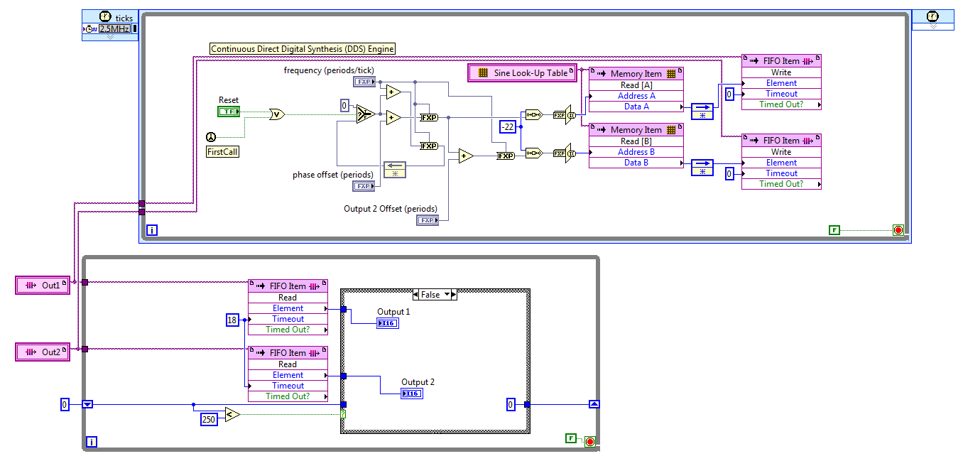
FPGA: Change the sinusoidal signal generator
The sine wave in the FPGA palette generator, that's what I need to do
but he can't exit do 'cosine', which is outside of 90 degrees. I need 120
degrees. To avoid discouraging, I opened the façade on the sine wave
Express VI generator that turned into a normal sup - vi. I changed the
a digital constant corresponding to 120 degrees out of phase, and the name was changed
of the output pin.The module will not compile. First mistake was a wire that was a type of variable, the
Fix suggested to check a box for pre-allocating did not work so I made the table
the length constant of 1024 (that is, it is supposed to be). Following error was
that one line of vhdl file was too long (32 k characters for a specification of length 4 k max
characters).Just for grins, I put the original VI Express return with the release of cosine and
It builds correctly.There was a big damper on the modification of the vi. However, I didn't know that
simple conversion to a subvi and the tweak of a constant value would break.Is it possible to get an updated the express vi for this application, or advice on how
changing the text that is there? The compilation breaks mainly online VHDL
length associated with the range of 1024 points.I can roll my own generator of sinus by using some examples, not a big problem but
It will cost you some time. Another option might be to run two generators of sinus
and specify a different phase, but I'm not convinced that over time they
will be exactly synchronized. Change the Express VI is a much better
option.Thanks in advance,
Bill
I discovered the hard way that LabVIEW 2011 has no records. After reviewing various options, I settled on the FIFO. The code presented here works well, but it is not save space on the FPGA to the wire using two generators of sinus with a phase difference in hard on one of them. For now, I'll use two sine generators, if this turns out to be unworkable in practice due to the relationship of phase adrift, then I'll look at it again.
The frequency and phase of the compensating controls are fixed point numbers formatted in zero whole bit and a 32-bit word. Bed down while the loop is synchronized with the loop timed by the FIFO, FIFO of 18 ticks timeout is two more than the 2.5 MHz in a loop which is a ditch-16. The IF block in the lower part, while the loop cut update control up to 10 KHz, 60 Hz sines more quickly.
Great experience, thank you for the help.
Kind regards
Bill
-
HP Photosmart, can not sweep, the printer works.
ProductName: HP photosmart C.4289, Internet Exploder, Windows Vista.
Printer works but no scans, reason: Solution Center: react; No hp devices found.
Actions:
Download driver, 96% progress to stop and return. Signal: Irreparable mistake by installation.
Analyze: Plugin HP Installer recovery does not work.
Signal of microsoft / windows: there is a problem, why programming is not working properly. Closed programs, as soon as the solution is following is the available information.
Scan of doctor: print, scan problem reg. Solution: download again.
Microsoft solution: download again.
conclusion: no result.
I hope you can help me. Thank you.
This message was not a solution, it is a correction. In the first mail of the number of the printer was incorrect.
Maybe you are looking for
-
Satellite Pro L300-152: deleted folder - but need Recovery DVD reocvery
Hi, I recently bought a toshiba laptop *. I accidentally deleted the file on my disk 'data' through formatting the drive.I was told that I needed this folder in the hard drive to create my recovery disk This file is now gone.Is it possible that I can
-
Width of the different track compared to the other nets
Hello, I have the following problem which is quite crucial for most business users. Let supposd design consists of three lines 'nets. One of the exhibits potential 10V, a second and third pieces 1000V and 1010V, respectively. Then it is clear that a
-
look to the top title. my windows media player won't rip music. used to RIP is fine, but I'm me comp. recovered, and now it will not. It's all fine.
-
Sorry if this question has already been addressed, but I couldn't find anywhere. I have a western digital 2 TB USB drive. It works fine on my intranet (my laptops and other devices can access). I have a sticky Ip address and would like to be able to
-
How to print both sides on hp office jet 2540
Hi, I have a Mac and it is updated to the latest version, and I have the hp deskjet 2540. I wonder how to change print settings to double-sided. I have looked everwhere and tried everything. Help, please.