calculation of waveform
Hi all
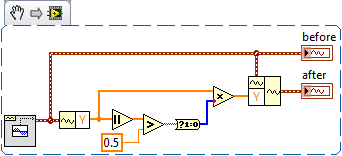
I use NI 9401 as a digital output to control a switch in a simple circuit and using the NI 9205 module for measuring the voltage across a diode in the circuit. The control signal of the swith is a square wave. So what I do is to get two values of the voltage the diode: topic 10us before the falling edge of the waveform and 200us after the falling edge. Then I need to use both voltages to do a little math, let's say, add the two values and trace amount vs time. I am a starter of LabView and have no idea how to do that. Can someone help me?
Hi wademao,
You'll need to do is set up a trigger of reference (descending the wave front) and then read pre and posttrigger samples, something similar to the following illustration:
Then according to the sampling frequency that you use to acquire your analog signal (i.e. voltage at the terminals of the diode) you can exteact predeclenche 10us samples and 200us sample taste samples posttriggered
Can you give us some more details on your hardware configuration? The NI 9205 and NI 9401 in the same cDAQ chassis? What is the model number of your cDAQ? You can generate your relaxation with your NI 9401 (for example on DIO0 - pin 14) and then feed this entry PFI0 sigal (pine 28 or 36 depending on your module) of your NI 9205 module. Once finished with wiring to the top of your material, you can use the examples in the following article to set up your triggered post/pre acquisition:
Tips and Techniques in Acquisition of data triggering - NOR-DAQmx
However, if you are a beginner with LabVIEW I recommend you to read through the following items:
Tutorial of Acquisition of comprehensive data
Learn 10 functions in NOR-DAQmx and handle 80 percent of your Applications of Data Acquisition
Tags: NI Hardware
Similar Questions
-
Hi all
I am a fairly new user to Labview and am trying to create a program that: watching the entries in different modules (9213, 9217) CompactDAQ sensors check errors and then uses data from some final calculations like averaging etc. I've set up a small piece of code that includes the main functions that I am trying to accomplish. Now I'm rather uncomfortable with getting set up and assigned channels, then pass these data in a while loop that continuously pulls the data from these sensors.
I have the vi calculations complete and complement the inputs of channel UI, now, I'm working on the side of data manipulation and reading things. The waveform D 1 who comes to read function is currently divided into components I want (given String Name and Y). He then transmit this information out of the loop via a queue which transmits to the parallel loop below that will perform the verification errors and calculations of average. There are some things that make it difficult. I showed the 2 sensors in my example, but in the actual program, there may be up to 400 entries. The problem is that not all of these sensors will be used on all the tests that the software is used for. To use the entries in the VI test for example: if I'm trying to the average of these 2 entries to create a common value, but then on a test, sensor 2 is not there, it must be recognized that fact and not use it in the service average.
So to get down to it, I want to create something that can look through the D 1 waveform data groups, determine what these values are, then perform the functions necessary for these numbers once they are identified, then pass on the calculations of VI where it displays then usable for user information. I think I'm having a problem with the finding in sorting than what I thought at makes me think that there must be an easier way.
If someone has encountered this? What is my explanation of what I'm trying to make sense? Let me know and I can clarify.
In terms of features, I don't see anything wrong. with respect to the effectiveness we must remember some general indications. These issues that I bring to the top will not affect your code now since your stack sizes are very small but can start to create the fragmentation of memory and slow down the software if your stack sizes are much larger and the software runs for a long period of time.
1. try not to use the table to build. Whenever you use a table built labview creates a copy in memory. Try to initilized your berries and replace subsets.
2. as much as you can try not index tables or unbundle cluster several times. try to perform as many tasks as possbile in one shot. (what was obvious in your second loop)
In addition, he's looking good.
I made a few changes to your code and attached to it. I wanted to give you a different on her opinion as it relates to being able to control entry and exit of programitically, if you had a look up table. I do not have the same changes to your second loop but I can guide you through what to do if you do not want to go in that direction. Yet once your original code is well done for someone who is new to labview, so don't feel you need to follow the new design of VI. Just try to remove the table construction and multiple indexing as a good habbit programming.
-
Number of averages for time waveform acquisition
Hello
It is on the configuration of the device - settings of the acquisition.
in the parameters of the collection file, can I know is there a way to feed the number of averages and % of overlap between averages aquire waving time.
Thank you!!
BR
Pattabi
In version 3.0 of InsightCM, we will support an average and overlap on the data of the spectrum Viewer. These settings will be applied only to the visualization of the spectral data and will not apply to calculations on the waveform or spectral data form.
This will meet your needs? Or are you interested in doing an average and are superimposed on the spectral data to then be used for calculations that are based on spectral data - such as 1 x Magnitude, etc.. ?
Thanks for the question.
-alan
-
Calculation of power using Rogowski coil
Hello
I am trying to decide if I should build a VI or if SignalExpress is capable of calculating power based on my selection of transducer.
I'm trying to calculate the three-phase power of a system using a 2-wattmeter method. I have a NI cDAQ-9178, Rogowski and a winding module NI 9215.
Since the output of the Rogowski coil voltage is 90 degrees out of phase from the real wave, I can't simply multiply the voltage and current waveforms for the real power. I need to integrate the signal of the Rogowski coil and then multiplying two signals together.
Is there a SignalExpress option which allows me to integrate the signal or phase change the output voltage of Rogowski?
Thank you.
Hi Jcesar,
I think that the best way would be to incorporate them into LabVIEW, if you have this option, other wise, a way to do in SignalExpress could also be to add a step in LabVIEW on your SignalExpress project, here you can find a guide who has something similar with a numerical integration.
https://decibel.NI.com/content/docs/doc-12714
Hope that you may find useful!
-
My goal is to create a graph of waveform with the following criteria.
- Click/double click on the chart to draw the cursor at the nearest location.
- Draw a rectangle to zoom.
- Indicate a way to zoom out.
With the code below, I can double click to draw the cursor to the closest place and draw a rectangle to zoom. However, I can't figure out how to zoom out.
What I am doing wrong?
(Measurement Studio 8.5 & Visual Studio 2008)
Imports NationalInstruments
Imports NationalInstruments.UI
Imports System.DrawingPartial Public Class PlotData
Inherits System.Web.UI.PageProtected Sub Page_Load(ByVal sender As Object, ByVal e As System.EventArgs) Handles Me.Load
If not IsPostBack then ' generate initial random signals
myGraph.PlotY (GenerateData (1000))
End If
End SubProtected Sub myGraph_PlotAreaClick (ByVal sender As Object, ByVal e As NationalInstruments.UI.ClickEventArgs) Handles myGraph.PlotAreaClick
Dim plotX As Double, foot As DoubleInverseMap (myGraph, provable, e.Y, plotX, foot)
myGraph.Cursors (0). MoveCursor (plotX, foot)"To display the click coordinates and plot
cursor_lbl. Text = "X:" & "Y:" & provable, e.Y & "pX:" & plotX & "pY:" & foot
End SubPrivate Shared Function GenerateData(ByVal dataLength As Integer) As Double()
Sun data (dataLength) As Double
Dim rnd As New Random()For i As Integer = 0 To dataLength - 1
Data = Tower. NextDouble() * Math.Sin ((i / 3.15))
NextReturn data
End FunctionPrivate static void InverseMap(ByVal graph As NationalInstruments.UI.WebForms.WaveformGraph, ByVal xClick As Integer, ByVal yClick As Integer, ByRef xPlot As Double, ByRef yPlot As Double)
Dim ACE Double, Double xMin xMax
Dim yMin As Double, yMax As Double
Dim plotLeft As Double, plotRight As Double
Dim plotTop As Double, plotBottom As DoublexMin = graphics. XAxes (0). Range.Minimum
xMax = graphics. XAxes (0). Range.Maximum
yMin = graphics. YAxes (0). Range.Minimum
yMax = graphics. YAxes (0). Range.MaximumWith the chart. PlotAreaBounds
plotLeft =. Left
plotRight =. Right
plotTop =. Back to top
plotBottom =. Bottom
Ends withxPlot = ((xMax-xMin) * ((xClick-plotLeft) / (plotRight - plotLeft))) + xMin
yPlot = ((yMax-yMin) * ((plotBottom-yClick) / (plotBottom - plotTop))) + yMinEnd Sub
End Class
InteractionMode = "ZoomX, ZoomY, PlotAreaClick" >
Hi Steven,
The solution that I can think of is to use a special key (i.e. Control) as well as with a mouse click to zoom out. It will take some work on your part.
The plot are click event does not provide any information on if there is a press of a key. To do this, you manually from the client-side information on the side go server you had pressed the button control key while you click. This can be done using a HTML hidden field.
How to pass the CTRL button information from the client to the server?
(1) adds a hidden field (say with the attributes id and name the value "ControlKeyPressed") inside the form that is rendered by default in the .aspx file.
(2) at the end of the form, write the key down and key events on the document.
(3) in the javascript event handlers, when you press the control key, the value of the hidden field as 'Y', in all other cases, the hidden field value is set to 'n'.
The .aspx code would look like,
onplotareaclick = "WaveformGraph1_PlotAreaClick" >
Now, when there is a PlotAreaClick event triggered on the server (here meaning the c# /VB code), the server manages the parameters that the client had sent. You can access the parameters as follows,
Dim str As String = Context.Request.Params ["ControlKeyPressed"] as string
Now, your PlotAreaClick handler would look like,
protected void WaveformGraph1_PlotAreaClick (object sender, e ClickEventArgs)
{
If (IsPlotAreaClick())
{
//--------------------------------------------------------------------------------------
Important note:
You will need to keep a stack to remember the beaches of x / axes there before setting the new ranges.
Keep the battery in a session variable or a variable application or make the battery a static variable.
First, push the current x / go to the battery.
//--------------------------------------------------------------------------------------Then, complete the tasks that you intend to do.
The new range computed value x / there axes.WaveformGraph1.XAxes [0]. Range = new range (0, 1); It's your new calculated range.
WaveformGraph1.YAxes [0]. Range = new range (0, 1); It's your new calculated range.
}
on the other
{
Pop the stack item and assign the range x / there axes.WaveformGraph1.XAxes [0]. Range = new range (0, 10); Here, you use the skip value of battery.
WaveformGraph1.YAxes [0]. Range = new range (0, 10); Here, you use the skip value of battery.
}
}Private Boolean IsPlotAreaClick()
{
Dim str As String = Context.Request.Params ["ControlKeyPressed"] as stringIf the value of the parameter is 'Y', then it means that the action was a zoom out, not a ground area click.
If (str == 'Y')
Returns false;
otherwise returns true;
}I hope this helps.
-
FFT calculation... How it works (in DIAdem).
Hello
I am a new user of tiara, my apologies for my experience in.
My task is very simple, calculate the FFT of a waveform channel sampled at 200 kHz (in this case is a second sequence of length 1). I see that DIAdem offers several ways to perform operations, so I tried some people. Start with the following configuration I used the Amplitude peak both the RMS Amplitude:FFTIndexChn = 0
FFTWndFct = "Rectangle".
FFTWndPara = 0
FFTWndChn = 0
FFTWndCorrectTyp = 'No '.
FFTCalc = 0
FFTAmpl = 1
FFTPhase = 0
FFTCepstrum = 0
FFTAmplType = "Ampl.Peak" OR "Ampl.RMS".
FFTAverageType = 'No '.
FFTAmplExt = 'No '.
FFTAmplFirst = "Amplitude".
FFTIntervUser = "LengthStartOverl".
FFTIntervOverl = 0
FFTNoV = 0
FFTIntervPara (1) = 1
FFTIntervPara (2) = 200000
FFTIntervPara (3) = 1Looking at the results in both cases (PEAK or rms) I see that values of output channels (amplitude spectrum) are very low respect to those than I expected. In particular, if you calculate the power (using the theorem of the Parseval for discrete sequences) of the sequence in the frequency domain and the power of the sequence in the time domain, we have a big difference between the magnitude of the values (what I notice is proportional but NOT equal the number of samples involved in the calculation of TFF). In theory, they should be equal (for the above theorem).
So my question is: How does the tiara calculates the FFT? (I've read the help and it seems a classic DFT...)
And why this big difference between the values of the two powers in the time and frequency domain?P.s. If I calculate for the same values of power sequence both with Matlab, I find the same number.
Thanks a lot to anyone who wants to help me.
Ciao,.
Federico
-
Waveform output n-times with DAQmx screws
Hello
I want to output to an analog waveform 1 d a specified number of times.
The problem is that I am converting a Labview 7.1 to 9 Labview program. To do this, the Legacy DAQ screws must be replaced with modern versions of DAQmx.
The old 'AO Start' VI allowed the user over the "number of iterations of the buffer" and it would simply exit the waveform given that several times.
There seems to be no way to do this with the new DAQmx screws?
Other people have said:
"To produce an n-time waveform, simply call the VI"DAQmx Start Task"that many times."
This won't work, as long as the task is stopped before trying again - HOWEVER, this is not the service I need for the following reason:
-There is a delay between the end of the output waveform and the beginning of the next iteration of this waveform, in the order of 15 ms. It is unacceptable, there should be no delay.
"A form of continuous output, just wave wire wish all waveform to the 'DAQmx write" VI".
It is also unacceptable that I went out on four-lane 1 MHz, with iterations of waveform more than 100.
Does anyone know how to produce a waveform of 1 d n-times without the problems mentioned above?
Thanks in advance,
Chris.
Hi Chris,
The best way to get the functionality that you are looking for must first consider the size of your waveform. Let's say for example it is 1000 samples. If you want to generate this amount of waveform a N cycles, should perform a simple calculation to take the size of waveform table times the number of iterations, and set up a finished task of output to the output as many samples. So let say we want to exit 20 cycles of our sample of 1,000 signals, we would put up a VI of Timing DAQmx for finite samples, and samples per channel at the output of the task must be 20,000 samples. Thus, you generate continuous 20 cycles of your waveform before going out and turning off the task.
We will find a good example of base from here, make over, change the waveform to VI to your real table and set the terminal of samples per channel to the amount calculated in the way I did above.
-
Hi all
I read some TDMS files I created during data acquisition. The thing is that when there is no input, I pick up a low amplitude noise (low compared to what I am probing) which of course was recorded in my files.
I want to set a threshold of amplitude of the signal cut. So when the amplitude is less than this limit, the waveform will be all zeros and when she is at or above that threshold I will deal with my original wave normally.
I tried to do it with a case structure (REAL: output is a constant of waveform elements, of zeros and the initial stage of dt-FAKE: get the original waveform without any editing) decision but accidents of VI.
Could someone suggest an effective way to achieve this? If not with the decision-making process but the noise filters? My analysis VI already performs many calculations, so I would do something very simple and intuitive without compromising the resources of the processor.
Thank you very much
Panos
So that we can reproduce and fix the crash, it'll be great if you could post an example VI as well as some example data.
With respect to the threshold, it seems that you might be looking for something like this:
Herbert
-
problem while conspiring waveform of the signal in real-time
Dear Sir
I use LabVIEW8.2 and USB1208FS for data acquisition. I have configured hardware with LabVIEW and data in real time using the Universal Library VI AInScBg.vi. When I draw my signal on the waveform (amplitude vs. frequency) then on axis x frequency ranges from 0 ~ 0.49 hz. I have change the sampling rate of 1000 Hz to 4000 Hz, but on the x-axis without frequency change occurs and it is set at 0.49 hz. Can you please guide me how can I get the frequency of my own interest on the x-axis.
I enclose you daughter of LabVIEW for reference.
Kind regards
Muhammad Irfan
Student
UTP Malaysia
0060149087570
Simply change the text label of the x-axis of frequency does not automatically the correct calculation. You do not pass in the sample information in the service spectrum, so you get no frequency information. You can see the strain on the entry point. The function expects a data type of waveform as input. Without it, the dt will default to 1. Then, use the function create a waveform and add information from dt to it as well as your table of Y.
-
How to convert Brown waveform table Orange table
Hey,.
I'm trying my table in a box formla so I want the individual values in this table, but I never came across the Brown son of waveform
I have attached a file paint below, I hope that aid to explain what I mean
I want to go find the frequency & phase of my wave is it able to use thoes values in a calculation
Thanks, I hope this makes sense.
Resolved, regret that turns brown dotted line is a cluster not a waveform.
-
Hello
I data signals that are scrutinized every 100ms which are used for the calculations. I also display these data signals after a little massage as waveforms on operators HMI. The operator would also take the data points in the waveform and bring in excel for the purpose of data retention. Now for the purposes of the calculations, the mark of 100 ms period is good, however, the operator wishes to the wave shape have a period of 1 s. Is there a property node or the similar function block which would allow the waveform function block query data at a slower pace?
Thank you very much for the help.
I don't usually recommend screw Express, but there is a Compression of the sample one that could do the job for you.
-
generation of buffer desired waveform ╔chantillonnage clock and clock frequency sample resulting
Hello, I'm trying to generate a square wave on an ongoing basis for NI6221 DAQ to 2 kHz. I use the example of Cont Gen tension Wfm - Int Clk.vi, which works great for my needs. However, the synchronization frequency setting is sometimes different frequency resulting, according to the choice of the samples and the Cycles / buffer. Tracking dozn the origin of these variables, all come from the nodes property of the moment-DAQmx in Buffere waveform generation (multi) .vi, where the input and output frequencies are not the same. Now, why is it so? What is the way the rate is calculated? I guess it's related to an internal approximation of the Council divided by sweep sampling frequency, clock but how exactly?
I found some notes in the help (see figure), with a few diagrams of the oscillators according to the DAQ (M type) card, but then I'm lost.
Thank you very much
Virgilio
The AO sample clock is generated by dividing down the time base. If you select a clock frequency sample that can not be achieved by dividing the time by an integer base, the sampling clock frequency will be rounded up to the available sample rate nearest (it might be interesting to note that tasks HAVE always round the frequency rather than rounding to the nearest available).
For example, the maximum time available for AO internal base is 20 MHz. If you select a sampling frequency of 300 kHz, this wouldn't be possible (20 MHz / 66.66666...). Instead, ~298.5 kHz will be used (20 MHz / 67).
Best regards
-
Weighted Bandlimited a calculation of rms noise
Hi all
I want to calculate the band including a weighted rms noise. I'm able to calculate noise from rms to an analog signal without any bandwidth limitation. Find the attached vi for details. I want to limit the bandwidth to some known values (say 20 Hz to 20 kHz) and then calculate the rms noise.
Please advice.
Thank you best regards &,.
Siva
Siva,
What is the problem you are having?
I do not have the Sound and Vibration Toolkit, but when I replace it with a filter from the palette of Signal Processing, I get changes in bandwidth and in the calculation of rms. The RMS.vi of the mathematics > probability & statistics palette produces the same value you use the VI of statistics. Based on average DC - RMS.vi Signal Processing > range of measures of waveform produced smaller values on the 3 orders of magnitude.
Lynn
-
How can I get the instant value of waveform
Hello
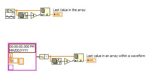
I have a generator of fishing into a waveform display. I would like to be able to acquire the instantaneous amplitude (I mean the instantaneous amplitude, which is now generated - you might think this is the last value generated thus) generator of fishing and be able to display on the front panel (I also use the value of doing other calculations). I tried several approaches and can't seem to get an instantaneous amplitude out of my wave form permanently.
Thanks for any ideas or suggestions.
Hello!
You are just looking for the value of the most recent (or last) of a sinusoidal signal generator?
Or am I misunderstanding the question?
-
FFT waveform (file converted from Matt file lvm) - how to overcome the error dt < = 0?
Hello
I use a lvm file after conversion of Matt file. I wanted to get the fft spectrum. I get this error message this dt waveform<>
How he overcome?
I have attached the matte file and the vi that I used.
Best regards
FESMI
The Forum is a bit special files that can be attached. Creating a zip file often works. Sometimes, you can change the .txt extension. If you change the extension, please indicate in your message which was the extension of the moose.
It seems that data in the file has a time column and a column of amplitude. The LabVIEW waveform data type is a cluster of a table of amplitudes (Y), sampling interval (dt), from the time (t0) and optional attributes. That's what the power spectrum VI requires as input. The t0 values is not used if the default is fine. the value of dt can be calculated by the difference of the two adjacent values in the time column. Given that the first value is equal to zero, the second value is equal to dt. Use the primitive to build a waveform of the palette of waveform. Expand it to view the dt element.
In the VI attached all lines is an indicator that contains your saved default file data. Graph XY plots that data. After subtracting the way to get rid of a continuous component, the data is converted to a waveform. The power spectrum is calculated and displayed using the same VI as in your program. It also uses extract several Information.vi tone for the frequency and amplitude of the main peaks in the data.
Interestingly, the lower frequency of the spectrum a harmonic of 60 Hz while the tops are almost sharp space 4 kHz ~ 100 Hz apart. The broad peak near 2.1 kHz does not seem to have noticeable components to 60 or 100 Hz.
How to avoid the Type of dynamic data (DDT)? Stop using screw Express! For reasons known only to EITHER screw Express a deliver their outputs via the DDT. Except when you open the block diagram of the express VI, there is no way of knowing what the underlying data structure on a thread of DDT.
Lynn
Maybe you are looking for
-
I don't remember my security questions.
I am asked to provide security to buy something, but because of many years, I forgot my account and their Email is no longer available due to inactivity. Is there a way I can get these questions? Thank you ~.
-
My laptop has 4g of memory that I want to move to 8 GB. Crucial scan shows 1 slot is under the keyboard on my Hp 15-r000na. It's not below.
-
Cannot download the drivers for HP 2000 2D28TU for windows 8... Help please.
Hi all I have formatted my system for the first time since I bought. My laptop is HP 2000-2d28TU. I can't download drivers for windows 8. When I bought the laptop from the provider. Seller says that register just your laptop on hp's website, you can
-
separate the keyboard of Acer switch 11
Hello! I have an Acer Aspire 11 switch SW5-171- 39 LB. This model allows me to separate the screen keyboard. Sometimes, I was hoping to be able to separate the display and place it in a location which is at eye height and leave the keyboard on the de
-
Dear Sir. Edit, cut, past, delete and copy cell mind my authorization... pls help and by setp setp... MicrosoftOffice 2010... Thank you best regards &,. Amit Jain