Card FPGA and data acquisition synchronization
Hi, we are control and data acquisition of several hardware devices (including Photodetectors and translational stages). Until last week, we used all the controls and acquisition using a PCIe-7852R FPGA board. However, we decided to move the acquisition part to a PCIe 6363 DAQ card to improve the sharpness of the tension. During the test, I found that the internal clocks in the FPGA and the DAQ cards are slightly inconsistent (not just a phase delay, but a difference in the period).
I know because I have generated a square wave (period = 20) using the FPGA and gains using the data acquisition card (at a rate of 200 kHz, that is, 1 taste every 5). I have observed acquired place shifts 5 every 5 seconds approximately. Such a change does not occur if the production and acquisition is done using the same Board. Therefore, the only explanation is that the data acquisition and FPGA cards clock frequencies are different. According to my calculations, the percentage difference between their time clock must be 5/5 s = 0.0001%.
Therefore, I wonder if there is anyway to synchronize clocks between them. Or, is it possible that I can drive the FPGA clock-based DAQ hardware, or vice versa? Also, please let me know if there is something trivial as I fix.
Thank you very much.
Kind regards
Varun
Hi Varun,
my post was only one solution...
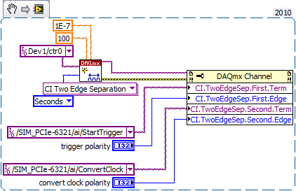
Your data acquisition card may take an entry to control sampling of trigger. In this mode, samples draw on a rising edge of the external clock signal. As long as you stay within the limits of the DAQ (100 MHz for your card) material sampling works perfectly. There are even examples coming with LabVIEW explaining how to program your data acquisition card...
This mode use you your FPGA as clock source sampling for data acquisition. Both will run on the FPGA clock in sync. When the FPGA is a bit out of 40 MHz, so it won't matter because both devices are triggered on the same clock signal...
Tags: NI Software
Similar Questions
-
motion control for vertical actuator and data acquisition
Hello
I am a researcher (a branch of civil engineering) geotechnical engineering and I have very little knowledge about the acquisition of control and data motion, so would need a lot of help from the experts OR. I have only knowledge base on these 2 aspects based on my reading of some materials on the Web site of NOR and youtube videos, so I hope that you bare with me
 . Here are my questions:
I am trying to build an actuator which will be used to push a probe (a penetrometer with a load cell to measure the resistance of a soil sample), resembling the concept, photography in the attached file. I need to have these criteria for my system:
(1) actuator, which can push the probe at speeds between 0.01 mm/s - 300 mm/s with precision and move the probe cyclically (upwards and downwards) in the vertical direction
(2) load expected on the probe into the ground range: 0.02kN - 6 kN.
(3) necessary to get the load cell load data and the speed of the probe.4) able to control the actuator to a PC (speed and posotion) and monitor data from transducers and data log time even the transducers.
Guess my beginners is that I will need:
For orders:
(1) software - LabVIEW and NOR-motion assistant(2) controller - NI PCI-7342
(3) driver/amplifier - analogue servo AKD Drive
(4) motor - motor brushless servo AKM
For the acquisition:
(1) software - based LabVIEW development systems(2) amplifiers or other device - no idea what type on the conditioning of signals
(3) data acquisition device - no idea what type
Since I'm a beginner, is - that someone might recommend components (hardware and software) for the control and data acquisition. I'm on a tight budget, so I thankful if someone could help me to recommend components good enough to build my system.
Thanks for your help.
At these rates, you will need to run the sensor for the cDAQ. You can configure the analog output on the Tritex nationally on the position. There is an adjustable filter that you can set in order to get a clean enough to 300 Hz signal. When you learn about the Tritex, make sure that let you them know what comms and e/s that you want to use. If I remember, not all options have worked together. The analog output may need to be my, but you can put a resistance through the acquisition of input data to get the voltage instead. I don't remember all the details. You should really not too much on the Tritex/LabVIEW side. You will send your movement parameters (beginning of end of race, speed, position, accel, cut), and if you cycle (I believe you) or simply running in a loop. You could also just be able to use the functions of jog. When you get close to knowing exaclty what you need, PM me and I'm sure we can work something out with the drivers. You need only the basics. In fact, you could probably do this all your movements via digital and analog i/o.
-
delay between the trigger and data acquisition
Hi, I use NI SMU-6368 as a tool for data acquisition. In my experience, I use an external digital trigger to start taking measures of a thermistor.
However, before the experience, I want to know the time that elapses between the detection of the trigger signal and data acquisition start time.
Is there a way to do this?
Here's the kind of thing I configure to get an accurate measure of time of t = 0 trigger signal to the
the actual first A/D conversion. It may be too much for a measurement of the temperature, but you should get
the right track.
-Kevin P
-
Control and simulation and data acquisition
Hello
I am applying to motor control in Labview. I'm sampling speed from DC engine in real time through an acquisition of data. (my sampling time is 1000 samples per second)
Then wrap speed as input to a Simulation (simulation and design of the order) and inside the loop simulation, I have a PID controller. The PID has the actual speed of the engine for the acquisition of data and the engine reference speed as input.
Reference engine speed comes from the generator of signals (control design and simulation-Simulation) and is a waveform.
My step in the engine size is 1000.
I am running this application real-time and drawing the reference signal and the motor real signals. I run into several problems with regard to the calendar.
1. when I change the size of the step of the simulation loop, the frequency of squares of reference also seems to change. For example. What step size = 1000, duration of pulse = 1 s. What step size = 100, pulse width = 0.1. (My pulse frequency is 1 Hz, Simulation clock - 10 kHz). How step size can affect the pulse width.
2. can you explain the relationship between the DAQ, the Simulation step size loop sampling time, Loop Simulation period.
3. If I want to collect different sets of data using sampling different hours, it's OK to change the sampling DAQ time without changing the size of the step of the simulation.
Would also like to emphasize that the DAQmx calendar under sample clock mode is placed in front of the simulation loop and the output is connected to the loop simulation.
Appreciate any help.
Hello
Maybe some screenshots of your code would help. Furthermore, what you have read your samples together with your DAQ screws?
(1) If you have a waveform, the output is specified as:
For example, if you change the size of the step of the simulation loop, you change the simulation time which are introduced into the signal generator and affecting the waveform that you see if you do not have a size quite small step to characterize the waveform that you generate.
(2) sampling DAQ rate is the speed at which samples are taken on the acquisition of card data itself. The size of the simulation step, help. "Specifies the interval between the time when the ODE Solver evaluates the model and updates the results of the model, in a few seconds." Simulation loop, still using, "Indicates the amount of time that elapses between two subsequent iterations of the loop of control & Simulation.". " "Step size determine the value of t that is introduced to the functions you use in the loop simulation while the loop simulation period controls simply to how fast you change the following t value. The sampling rate of DAQ hardware is a clock of completely separate hardware controlling the analogue-digital on the DAQ card converter so that you can get a deterministic dt between the samples being acquired.
(3) you can change the schedule for the acquisition of data, but you will need to restart each time the changes take effect. If you change the calendar of data acquisition and want your values to correlate with your simulation, you will need to change your size of step as well.
-Zach
-Zach
-
How can I use other companion DAQmax and data acquisition in labview code?
Hello
I'm new in labview and want to combine four different codes of labview and run them at the same time.
I use my data acquisition PCI-6071E and BNC-2120. I want to send an analog output (flat DC signal) to control a blower, an analog volmetre to a (DC) output pressure transducer, also receive data from a pressure sensor and hot wire probe.
I wrote four different VI for each of them (using DAQmax to output analog and DAQ assistant for analog inputs) and each of them works well, but when I want to use them together they do not work.
Anyone know how to make them work together?
Thank you
Pooya
To the DAQ Assistant, simply follow the instructions for the selection of multiple channels when you create (where he says quite clearly,' '
or to select multiple channels "). If already created, open the DAQ Assistant and click on "Add channels" at the top of the page. When you use a physical channel name, you simply click on browse instead of a single channel. Use the same
or for multiple channels. -
Error 200220 CRIO 9081 and data acquisition modules
Hello
I try to use a CRIO 9081 with NI9206 modules. Max recognize the chassis, but not the module.
When I try to add an acquisition of data associated with the NI9206 in Veristand, 200220 error message seems.
I have the solution, finally he was required to add a custom device to search for new engines and detect modules. Then, it is possible to interact with modules.
Thank you very much for your help!
-
Executable files and data acquisition Drivers
It is an interesting question that I hope someone can help me with.
My client has little code I need support. They have a card PCI-1200
card.
My understanding is the latest driver that works with this card is
Traditional DAQ 6.9.3.They have 6.9.3f3
Then I made the mistake of upgrading their code of 7.1 to 8.5. The code
works
on my machine. When I create an executable file, the executable works on my
machine;
However, when I try to run the executable file on their computer software
housing starts
and then stops. I get no error. The executable file only
don't
run.I wonder what I should create an executable with the driver
Version
6.9.3 on my development machine?Thank you
Dan
I solved the problem!
I downloaded the 8.5.1 engine LENGTH of Web site of NOR and installed on my target machine. It worked!
Previously, I copied the execution engine of my Cache on my development computer folder.
-
Assistants of programming and data acquisition
Using the flat sequence and DAQ Assistant, how can implement us planning algorithm to enable or disable a specific image in the sequence?
Do not use the flat sequence structure! You can't turn any image. Just one of the disadvantages of the structure of the sequence. They are rarely necessary. Flexibility, use a state machine.
-
The reading of data acquisition via tcp
Hello
I am building an application that controls an acquisition of data via tcp.
I have a JAVA program that communicate with labview, give a command and data acquisition starts. (So, I read the correct Java data at Labview)
My problem is if I try to read data acquired by data acquisition (continuous sample 1 k samples), I've read strange values.
I transform of double values in the string and send it via tcp.
How can I read it in Java? What type of socket should I use? What is a rate problem?
I also tried to transform small/big-endian byte order, but it does not work.I enclose a sketch of this part of the application.
Please help me, I try for 2 weeks!
Thank you all...I find the solution in the lavag forum.
I post here, if it can help someone.http://lavag.org/topic/16359-sending-LabVIEW-data-via-TCP/page__pid__99983#entry99983
-
water data acquisition motor control
dose anyone know how Precisele engine in labview using DAQ? Please tell me how I can do?
Concerning
Saeed
OK, I'm him giving the alternative energy source and just to control data acquisition rather then powered data acquisition, shell, I use the driver of transducer between the acquisition of data and engine or any other switch. Yes I m interested just in power of the engine after obtaining the indication of my sensor. Please tell me what I can use between the engine and data acquisition.
Kind regards
Saeed
-
BNC-2110, 6023E PCI card and Labview V9.0: sensitivity of data acquisition (change more little detectable voltage) is 0.002V
Hi, I use the software/hardware above to read a voltage of a potentiostat world Precision Instruments No..
I'm trying to record changes in voltage as low as 0.0003V but using the wizard DAQ, I seem to be limited to a sensitivity of 0.002V. This is the limit of real sensitivity or have I missed something?
Any help would be greatly appreciated.
Hi DCAM77,
Thanks for joining the forums!
The PCI or 6023E has a 12-bit ADC. In other words, it can make the difference between 4096 (2 ^ 12) different levels within the range of cards. The card you have has a selectable range by ± 10 V, ± 5 V, ± 500 mV or ±50 mV software.
This means that the minimum detectable variation will be 4 mV, 20 mV, 244 µV or 24, depending on the chosen range µV.
You should be able to use the ± 500 mV or ±50 mV to get the least significant bit (LSB) value, you need, even if it means that your signal is located between these values. If not, then you need to consider other materials to the application, or the addition of external circuits across the signal.
-
I am building a system and I need to help experts to choose the data acquisition card.
Hello world
I am currently working on a design project I need to take a data acquisition card that responds to the output of the amplifier. I'll build a force detection system which I have taken the following as detector and amplifier:
http://content.Honeywell.com/sensing/Sensotec/pdf_catalog08/008834-1-EN_Model_UV%20Bridge.PDF
http://content.Honeywell.com/sensing/Sensotec/pdf_catalog08/008638-1-EN_Model_53.PDF
Please recommend me which data acquisition card I could take. The only requirement I ask is to have less than 0.1% global uncertainty.
Thanks for anyone who can help
Since your amp has - 3db at 7 kHz and you need only 10 bits 0.1% will do almost any card with. USB-6009 is the lower end. USB-6210 the next step.
Then take a look at some other boundary conditions: do you need it calibrated? (Is there a QM adj. who could ask questions?) Space?, EMC/noise, entry, differential
Take a look at the USB-9237 with a conditioner bridge construction...
-
synchronize two loops for written tdms data acquisitions
Hello
I have two loops of different data acquisition. A slow acquisition of CAN (10 s/s) and an analog acquisition faster (30 samples taken at a frequency of 300 Hz), I need to synchronize these data for tdms writes for later analysis in DIAdem.
My example and the result in the DIAdem channel list is attached.
Thanks in advance!
Magnus
Magnus,
for a professional solution, you do not want to synchronize the devices on a hardware level. Since the material CAN work differently to 'traditional' DAQ devices, there are important things to take care of.
Please look in the viewfinder to LV example for the word "CAN". For example, you can choose the example 'several cards CAN and DAQmx map Wfm Input'.
Norbert
-
I get upgraded my laptop (HP for laptop - 15-r224tx) for Windows 10 but I can't find the driver for the controller of PCI Data Acquisition and Signal Processing. Please help me find the right one.
Thank you!
You are the very welcome.
It is the latest version of the W10 driver for this card model... see if this solves the problem, if you have not already installed this driver.
This package contains the installation package driver for the controller wireless LAN Realtek RTL8723BE/RTL8188EE in the laptop models running a supported operating system.
File name: sp72517.exe
-
Data acquisition in LabView for other suppliers DAQ cards that NEITHER
Hello
I am a beginner in LabView programming. I have a 32 channels base PCI card DAQ (i.e. PCI-1602 of the manufacturer, ICPDAS) and I want it to interface with Labview 8.5.
So how cards DAQ in Labview 8.5, which are manufactured by other suppliers that NEITHER? Should I DAQmx (or some other driver) for that?
What are the other drivers/components required to access of data PCI-1602 (device) of LabView 8.5 acquisition card?
(1602-PCI card driver are installed in my win XP and dispalyed in Device Manager).
Please provide some tutorial above mentioned the problem to interface.
Please guide me in this regard. Thank you
Waqar123 wrote:
Hello
I am a beginner in LabView programming. I have a 32 channels base PCI card DAQ (i.e. PCI-1602 of the manufacturer, ICPDAS) and I want it to interface with Labview 8.5.
So how cards DAQ in Labview 8.5, which are manufactured by other suppliers that NEITHER? Should I DAQmx (or some other driver) for that? You will need the drivers from the manufacturer, of the Board of Directors. In your case, "ICPDAS.
What are the other drivers/components required to access of data PCI-1602 (device) of LabView 8.5 acquisition card? Same as above.
(1602-PCI card driver are installed in my win XP and dispalyed in Device Manager). Ok. Then take you care of my 2 answers above.
Please provide some tutorial above mentioned the problem to interface. To learn more about LabVIEW, I suggest that you try to watch some of these tutorials.
Please guide me in this regard. Thank you
According to what you do with the DAQ cards, they can do the job however, from experience, there are some functions that I could achieve with the cards NOR that I couldn't with 3rd-party maufacturers. This does not mean that this is your case. However, it is worth noting that it took me a while to understand why the code has worked with a single data acquisition card (NOR) but not another (Non-OR).
The drivers that you have installed may or may not include examples and code in VI. They may be DLL. If this is the case, you can write LabVIEW "Wrappers" around these functions, as it will simplify your life. If the drivers are in the form of DLLs, and there are no examples of LabvIEW or available VI, you must read on node library function call.
R

Maybe you are looking for
-
Restore bookmarks causing 'no response' / lock up
Recently saved bookmarks firefox, because I have about 10 years ' worth of information. I also use Xmarks. Well trashed my bookmarks Xmarks and Firefox crashes when you try to restoreSince the firefox save. I even disabled Xmarks and it will be all e
-
Disconnected icloud, but always displayed photos
I used to have pictures enabled on my Apple TV and iCloud. However, he began to display some... personal photos and now I can't get down them! Ten of them are always displayed when the Photos app is hovered over. If I click on the application, or one
-
Satellite L300D will not recognize USB drive, except if the WIFI is disabled
I have a venerable L300D Satellite under Vista SP2. I also have a Fujitsu 40 GB SATA HDD of my old laptop in a USB2.0 caddy, with double USB plugs to require more current. I can sign in successfully caddy USB to my laptop Windows 7 via a simple USB p
-
Verification of the I2C and SPI Timing features to 5, 5V to 1, 8V
Hello I am trying to create a test setup that will allow me to characterize the sync settings for I2C and SPI bus on a part which cannot operate at 5, 5V to 1, 8V. I need to be able to characterize or at least test the limits of synchronization speci
-
It cannot make files in Windows Explorer w/Vista "copy paste".
In Windows Explorer can't do 'Copy paste' files in Windows Explorer. By the previous discussions, I uninstalled Internet Explorer 8 and re-installed (no difference). Even re-installed Vista SP2 (no difference). A running x 64 various supported Rootki