cDAQ-9188 t0 timestamp
Hello
I have 2cDAQ-9188 Chassisseparated by some distance and running a sort of coax or wire between them for the sharing of the clock is not feasible, nor tight very necessary synchronization. (Both being read by the same PC & software)
But I am tracking the time between them Jig by comparing just the time t0 reported on the waves produced in lu DAQmx.
My question: which is production/determine this t0 timestamp?
The result of the PC clock, or some calculation based on the task start and the number of iterations clock passed?
Or is it produced only by the Chassis 9188? If this is the case, I'm curious if the clock on the frame is silently being synchronized with the clock on the PC at certain intervals.
If t0 timestamps are all produced in the end by the PC clock, my algorithm of tracking little is pretty useless. It's okay if that's the case, I just want to know how I can say that I am tracking the cross-chassis jig.
Maybe I'm missing another way to follow the jitter between the chassis that I didn't think.
(FYI, this can be illustrated using simulated devices, it seems to be very similar to real hardware, so if it's not entirely logical I could produce a small set of code that shows what I mean)
On a note slightly unrelated, where are the congratulations for daqmx? LabVIEW Gets a lot of love, there is good reason, but this driver is awesome. Never heard someone sing his praises. Maybe it's because when we talk about what they are usually trying to understand why he is throwing a fit and refused to cooperate  but the fact that he can complain with lucidity instead of default in silence is yet one more reason it's so good to use.
Thanks in advance,
-Ben Phillips
Hey Ben.
The timestamp of t0 is referenced only from the PC clock. The time on the chassis is not synchronized with the PC somehow, and the frame time is not taken into account for the calculation of t0. To tell you the truth, the value of t0 is about the time that the task is started/weapon and has not a very strong correlation time of the first measure is actually taken, especially for beginning of tasks and others as triggered cases where there could be some significant time between the armament of the task and taking the first sample.
A way to get a rough idea of the LAG might ping the two chassis from the point of view of shared hosting. Time round trip to spend a single package on the chassis back will give you a rough idea of the LAG for single point applications, assuming that chassis hardware is starts at the same time (which would require a physical trigger shared connection).
If you are not concerned about the tight synchronization then I would say continue with your happy contempt for the moment because t0 probably doesn't provide much info useful to the case you're trying to measure.
Tags: NI Hardware
Similar Questions
-
buffer size and sync with the cDAQ 9188 problems and Visual Basic
Hi all, I have a cDAQ-9188 with 9235 for quarter bridge straing caliber acquisition module.
I would appreciate help to understand how synchronization and buffer.
I do not use LabView: I'm developing in Visual Basic, Visual Studio 2010.
I developed my app of the NI AcqStrainSample example. What I found in the order is:
-CreateStrainGageChannel
-ConfigureSampleClock
-create an AnalogMultiChannelReader
and
-Start the task
There is a timer in the VB application, once the task begun, that triggers the playback feature. This function uses:
-AnalogMultiChannelReader.ReadWaveform (- 1).
I have no problem with CreateStrainGageChannel, I put 8 channels and other settings.
Regarding the ConfigureSampleClock, I have some doubts. I want a continuous acquisition, then I put the internal rate, signal source 1000, continuous sample mode, I set the size buffer using the parameter "sampled by channel.
What I wonder is:
(1) can I put any kind of buffer size? That the limited hardware of the module (9235) or DAQ (9188)?
(2) can I read the buffer, let's say, once per second and read all samples stored in it?
(3) do I have to implement my own buffer for playback of data acquisition, or it is not necessary?
(4) because I don't want to lose packets: y at - it a timestamp index or a package, I can use to check for this?
Thank you very much for the help
Hi Roberto-
I will address each of your questions:
(1) can I put any kind of buffer size? That the limited hardware of the module (9235) or DAQ (9188)?
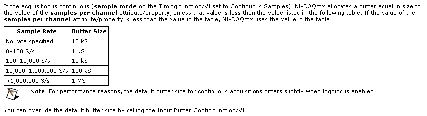
The samplesPerChannel parameter has different features according to the synchronization mode, you choose. If you choose finished samples the parameter samplesPerChannel determines how many sample clocks to generate and also determines the exact size to use. But if you use streaming samples, the samplesPerChannel and speed settings are used together to determine the size of the buffer, according to this excerpt from the reference help C DAQmx:
Note that this buffer is a buffer software host-side. There can be no impact on the material available on the cDAQ-9188 or NI 9235 buffers. These devices each have relatively small equipment pads and their firmware and the Driver NOR-DAQmx driver software transfer data device to automatically host and the most effective way possible. The buffer on the host side then holds the data until you call DAQmx Read or otherwise the input stream of service.
(2) can I read the buffer, let's say, once per second and read all samples stored in it?
Yes. You would achieve this by choosing a DAQmx Read size equal to the inverse of the sampling frequency (during 1 second data) or a multiple of that of the other playback times.
(3) do I have to implement my own buffer for playback of data acquisition, or it is not necessary?
No, you should not need to implement your own stamp. The DAQmx buffer on the host side will contain the data until you call the DAQmx Read function. If you want to read from this buffer less frequently you should consider increasing its size to avoid the overflow of this buffer. Which brings me to your next question...
(4) because I don't want to lose packets: y at - it a timestamp index or a package, I can use to check for this?
DAQmx will meet you if all packets are lost. The default behavior is to stop the flow of data and present an error if the buffer of the side host DAQmx overflows (if, for example, your application does not pick up samples of this buffer at a rate equal or faster than they are acquired, on average).
If, for any reason, you want to let DAQmx to ignore the conditions of saturation (perhaps, for example, if you want to sample continuously at a high rate but want only interested in retrieving the most recent subset of samples), you can use the DAQmxSetReadOverWrite property and set it to DAQmx_Val_OverwriteUnreadSamps.
I hope this helps.
-
Using instrumented hammer model PCB 086D 50 with the NI9234 module and chassis OR cDAQ 9188
Hi all
I need to try to shock with a PCB 086D 50 instrumented hammer hammer. I use the chassis OR cDAQ-9188 with the NI9205 and NI9234 modules. The hammer is connected to the NI9234 and accelerometers are connected to NI9205.
When I test the modules in SignalExpress I get very good results for the dog, but the accelerometers are ok. Also, if I am controlled the hammer OR Max where I have the option to activate the IEPE the result is ok. In SignalExpress, I couldn't find the option to activate IEPE.
I have no experience using software, but I started to learn. Does that mean that I need to program the system for my setup in LabVIEW? Also, the installer of the equipment makes sense, the modules that I plugged on the cDAQ can be used simultaneously? Should I have the additional device in order to use the hammer with cDAQ 9188?
Thank you very much
Emina
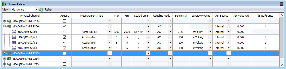
You can enable IEPE in SignalExpress. Here is a configuration for a single power hammer and three accelerometers a 9234-related.
You don't mention the model for accelerometers. They are also the IEPE sensors? If so, have what conditioning of signals you added before the 9205?
The Assistant Sound and Vibration (built on SignalExpress) contains an example of Impact Test. The Sound and Vibration Toolkit comes with a sample project for the impact test. With free evaluation period, go ahead and look at how one of these examples is implementing the configuration and the triggered acquisition.
-
How many quadrature encoders may be read together with the cDAQ-9188 chassis?
We will record position periodically 8 engines (at the same time as we are to the corresponding samples entered analog). It seems that the 4 built-in counters limited chassis to 4 encoders. Is this correct? I am familiar with modules of counter PLC which manage high-speed counting, and then the CPU posts periodically to update the total values. This is how the NI 9401 card would work?
Hi jtrout,
You are right the 4 built-in counters than the cDAQ-9188 chassis 4 encoders. The following article deals with the use of the NI 9401 card for encoder measures: http://www.ni.com/tutorial/7109/en/.
-
LabVIEW 2010 with CDAQ-9188 and NI9205
Hello
I use the NI CDAQ 9188 with the Analog Input Module NI 9205. The specification of the NI 9205 module shows that there
16 channel differential channel, or simple 32 took end. I use the 'DAQ Assistance' in Labview to configure the
Module OR 9205. But it only allows me to select 8 differential channels. After I put the 8 channel, then the
Terminal configuration allows no differential inputs. It allows only to CSR or NRSE entered.
I'm doing something wrong? I just bought the camera to use for 16-channel differential reading.
Thank you
Bobby
Hello
It worked.
Thank you
Bobby
-
Networking the cDAQ-9188 - no 'network devices' Max
Hi all:
I have problems connecting my NI 9188 cDAQ via ethernet to my computer. MAX does not display it in his repertoire, or it displays "network devices". Based on the guide NOR offer, I don't know what else to do (I can't access the modules in a LabVIEW project which is my problem).
I used the tool online browser that seems to be the equivalent of MAX and works very well - I can see the IP address of the controller and it shows what chassis slots are used by what the map.
I tried manually inputing this IP in a remote system to the MAX, but that hasn't worked.
Any ideas on how I can networks controller on my computer so I can actually use in a LabVIEW project.
I have LabVIEW 2012 32 Bit. Would a student version be the cause of the problem?
Thank you very much.
cuaerospace wrote:
I am familiar with the method you describe, but I agree with all the power cycling to get some of these products to work. I had to do this several times with the cRIO. Any chance you could give a little more than a description step by step explcit of your approach? Thank you!
Good so here's what I did to try to reproduce and to have a step by step of what I had to do.
Firstly I have reset my cDAQ so that it would be if all goes well in the mode that yours is. To do this, I pressed the button to reset for 5 seconds then. I have also all my network devices defined to "Obtain an IP address automatically" in the IPv4 settings in my network connections.
After that, I start MAX.
Go to devices and Interfaces > network devices, then I right click and choose Find devices. It took a lot of time and the list was empty, but then I noticed that while he was always looking in this window, the MAX window showed my cDAQ-9188, who was a white device. There, he registered the IP address as 169.254.93.149. At this point if I went to the device to the MAX I saw where he sometimes States under network settings that no network adapters found.
So I closed MAX and open my "view network connections" in Windows, I just searched that term in the start menu. Then for my device properties, went to the IPv4 properties, set the IP address of 169.254.93.0 with 255.255.0.0 default gateway. It is, so I'm on the same subnet as the appliance.
I then restarted MAX now when I go to the device under devices, network and network settings I can set static IP and subnet is 255.255.0.0 10.10.10.100 then save. Then closed MAX.
Then I went back to my view network connections, the static value of what I really wanted is 10.10.10.0
MAX then launched. Find my device that is always white, click Add the device. And then all is good. I don't know if all these steps are necessary, and I don't know if there is an easier way, but it worked for me.
-
Frequency control of NOR-9476 on the cDAQ-9188
I am using a cDAQ-9188 with a NI 9476 module, and I would like to control the frequency of the digital signals that the module was released. I tried to use the example of Pulse Train digital continuous with control of the frequency, but impossible to select the 9476 since there is no internal counter, and when I change the 'Digital output' task, the frequency control disappears. Is it possible to use the internal counter of frame to control the output frequency of the 9476? I need to get out a range of 0 to 1 kHz.
Most of my program would output a digital signal of a certain frequency every second in real time from a given table. For example, if I have an array of [10, 20, 15, 100,...], it generates a model of up/down of 10 cycles per second for a second, followed by 20 cycles (with a shorter period) for a second, then 15 cycles per second for a second, and 100 cycles per second for a second.
I tried to use avoiding to do, but it was very slow, with a delay of 63 ms between each cycle, when I wanted a 1 ms delay.
CDAQ-9188 has 4 counters built in, but you cannot access it by using the NI 9476-, but the NI 9401 module can access the built-in meters.
The good news is that you can always generate your pulse train, using counters, it generate on the PFI lines on the chassis itself and not through your module. If you need to generate more than a pulse train, or use all four counters, you will need the module NOR-9401/9402.
In order to get the speed, you will need to use the capabilities of hardware counters timing.
I hope this helps!
For more information:
-
Module AO trigger using PFI on the cDAQ-9188
I use a cDAQ-9188 chassis with an AO (NOR-9264) module. Is it possible to configure a PFI (channel on the frame) as an input signal to synchronize an AO channel with the trigger? Here's what I'm trying to do. I need a channel on the AO module to switch voltages in sync with the trigger when the user "push a button". So once the button is pressed, the channel of the AO will not change until the next trigger pulse.
Thanks for your help
Ben
Hello Ben
I hope you are well. The consensus is that it is possible. Have you tried this yet? If so, can you tell me what you have tried and how you made a lot of progress? I recommend the following VI example: Cont Gen tension Wfm - Ext Clk.vi. Are you able to get all the functionality you are looking for this VI. It was recommended that I'm showing you this. We find this VI under help--> find examples and then material input output &--> DAQmx-->--> voltage analog generation.
Please let me know how you are progressing and if you have need of all aspects of this example explained. Thanks for choosing National instruments!
Sincerely,
Greg S.
-
No reconoce cDAQ-9188 via ethernet
Hola Amigos
Tengo el problema of Quebec able & Automation, me reconoce el chassis cDAQ-9188, pero no sus modulos he intentado todo lo, that will be replaced by Recomiendan en sesion http://digital.ni.com/public.nsf/allkb/DF65FCF0DD20D71686257949007ECAA7 pero esta no obtengo resultados positivos, alguien could orientarme...
Lo agradeceria muchisimo
PD: Editor lo me appears
Hi pomontty,
CDAQ networked systems requires a host booking, to avoid conflicts where multiple hosts on the network could attempt to access modules at the same time. For this reason, you don't have access to your modules until you have selected the reserve chassis from the top of the window in the right-click menu or MAX on your device in the devices tree. You cannot also self-test or reset the chassis when you have not booked, which is why you see the error that you have set.
-
the cDAQ-9188 discovery method?
I have a cDAQ-9188 I prepare for use by customers in the area. These customers tend to forget IP addresses, and I would like to add something to my request to help. Something installed "NI Network Browser" on my development machine. I suspect it was DAQmx 9.2.2. This browser appears to be a shortcut to a web page of Silverlight being served off port 59648. The browser does a good job to list the chassis on the network, and I would like to know if there is a way to make this work in LabVIEW. It uses UDP or something?
I know that the standard method would be to ask clients to use the network browser, but I'll try match the SCXI-1600 user experience where you just plug in and it appears. I try to avoid making them run MAX or a browser or anything but my request. I know that I can avoid the MAC with the VI DAQmx step add network device, but he wants an IP address for an entry.
Thank you
Dan
Hi Dan,.
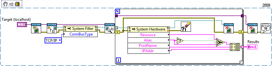
The API for the system setup OR was released earlier this year and aims to provide developers the ability to integrate MAX features into their distributed LabVIEW applications. The following code uses the API and should be a good starting point for what you need to do:
If you have any questions or encounter any problems do not hesitate to post back!
Best regards
-
Multifrequency 9223 9215 sync and 9213 in cdaq 9188
Hello
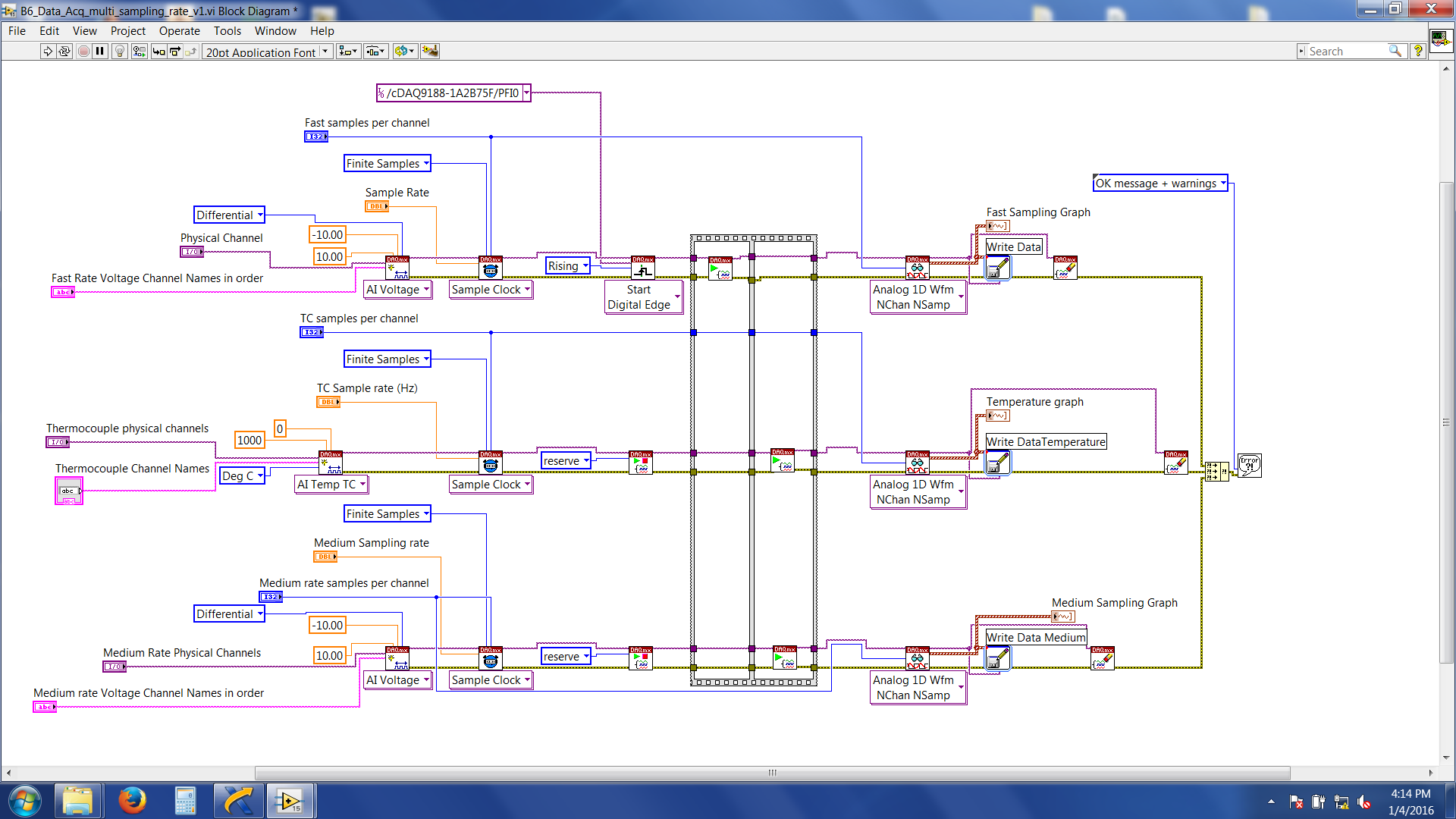
I'm trying to synchronize three different modules (NI 9223 and NI 9215 NI9213) every acquisition given to various higher sampling frequencies (e.g. 9223 = 1000 hz, 9215 = 100 Hz and 9215 = 2 hz) and write files to separate data for my task. I am using a cDAQ-9188 ethernet and all modules are in the same chassis. There is an external trigger (which comes from an external source) to start acquiring data which are wired connected to the PFI0 channel in the chassis. What I want to do is: whenever the trigger is high, acquire 10seconds of data according to different sampling frequencies high above and write in separate data files. I followed the procedure referred to in the http://www.ni.com/tutorial/5376/en/
Here's a snapshot of the block diagram
Now, the problem I am facing is the 'average frequency (NI 9215) data' and 'data of Thermocouple (NI 9213)' are acquired and written immediately after that I have start the labview program. Fast speed data (NI 9223) are not written, and wait for the trigger signal. And then it throws an error 200284. If I do just a finished sample rate on NI 9223 alone (without adding/attempt at sync with other modules) with expectation of release it works without any problem.
LabVIEW files are attached.
Suggestions very much appreciated and you wish all happy new year.
Thank you
Roy
Hi Roy,
'average frequency data (NI 9215)' and '(NI 9213) Thermocouple data' is acquired and written immediately after that I have start the labview program.
Yes.
You forgot to set a trigger to start these DAQmx tasks!
And then it throws an error 200284.
The description of the error says something like "use a higher timeout value. Have you tried that?
-
cDAQ-9188 Ethernet connection problem
We bought 2 cDAQ-9188 and I can't get them to connect to the computer via the Ethernet connection. I can make them work if I use a short cable (10 ft), but the location that I need them is about 180 feet away. When I do right click on network devices and select Find devices that it returns Nothing found. Is there any suggestions on what I might be wrong or what I should do to make them work? I'm running LabView 2010 SP1 and the drivers provided with the units of the cDAQ-9188.
Of course, the PC Ethernet card we use is low. I have them connected to a router and placed near the PC router, and now, they work very well.
-
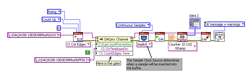
County of gated cDAQ-9188 edges with NOR-9402
Hello! This discussion is a branch of it.
Shortly, I want to count the random impulses of a meter of photons, which emits pulses that when her door is activated (and this should be done in a manner expected by HW), only when the door is active.
I separated this task in two: in timing HW emit pulses of door and to count the edges when the door is active. For the second task, I created a VI:
those who are more experienced could please tell me, if I do it in a right way? I'm a little confused on how to connect my device: random TTL of the photon counter should go to ctr0 PFI0 (in NOR-9402 this is the PIN 0) and what I generte of the first task (in fact, pulse clocked by HW) door and then must be connected to the terminal of the door of my meter (left unwired above) both at the entrance of the gate of the photon counter... There must be a mistake in the present, I guess that (otherwise I have to divide a wire giving my first task output and connect it to the PFI1 and at the counter of photons of entry door).
In your implementation of the second example, you have selected Ctr2Source as the sample clock, instead, you must use Ctr2InternalOutput.
The way I read your initial post, it sounded as if you wanted to limit the count while the low door signal. However, if the photon counter does not export the pulses during this time, it would be unnecessary to set up the break. Indeed, as you said it would be undesirable to do so.
To change the examples I posted to count regardless of the State of the portal, you can do the following modificaitons:
Example 1: Change the task to a task period pulse width (and the corresponding property node).
Example 2: Remove the break. Change the sample clock to sample on the shores of the Levant.
So now you will be pointing the samples on each rising edge of the gate signal. The count represents the number of photons during the previous impulse of the door. The returned data will be slightly different depending on the approach you take - sample-clocked version will return a sample on the first rising edge (which should read a counter to '0') where the period version will not return this example.
Best regards
-
Digital triggering PFI on a cDAQ-9188
I use a Campell data recorder to send a pulse of 5mV to my daq to trigger the recording of some accelerometers. I also have the code to stop acquisition when another pulse is sent, the code has currently a predefined sampling time how I would change.
Thank you very much
I'm glad that it worked. You get with the other examples?
There is a slight difference between the former and the latter. The one you posted just checks for the trigger of the judgment in software rather than in hardware, so you will be limited to verification of the digital line as you take more analog samples. If it works for you, but then that's fine.
One thing I would recommend is a stop button, so you can stop the loop if you want, without having to give up the program. It will ensure that you clear resources etc.
-
How to initialize a cDAQ Ethernet (9188) to autostart?
Hello
I have a LabVIEW program that performs tasks DAQmx (pre-configured via NI MAX). The material is a cDAQ-9188, connected directly to the laptop via an Ethernet cable. Both machines have static IPS (same subnet).
Question
Whenever we turn on the machines, NI MAX notes that the cDAQ-9188 is reserved and running. However, the C Series modules are reported as Absent (error-88705 code: "the specified device is not present or is not active in the system.) The device cannot be installed on this system, may have been disconnected or may not be installed correctly")
As a result, the LabVIEW program generates an error, because the physical channels required by the DAQmx tasks are not.
Workaround
Each time we spend in the entire system, we're going to MAX OR -> my system-> devices and Interfaces-> devices network-> OR cDAQ-9188 and click "post."
The test always succeeds and seems to be a sort of boot behind the scenes. After this step, the LabVIEW program works without any problem.
Questions
- This behavior is expected? If this is not the case, what could cause this?
- Is there any way to automate this initialization, so that the user does not need to click on "Self test" after each cold start?
Hi JKSH,
You can the make a self-test program.
I wouldn't say that it is an expected behavior. What has helped here, was a repair DAQmx and LabVIEW. But before do you I'll make sure that you have the latest drivers.
Maybe you are looking for
-
PDF attached used open - problem just started
This week, a PDF file attached to an e-mail gives error message "error downloading, the download could not be saved, because an unknown error occurred - try again. On the download window, the message is "failed, resource mailbox. Yet, I can save the
-
HP G053US 17: WLAN has become very sensitive, hardware ID is not driver provided by HP
I bought a new laptop, HP17 G053US of Office Depot. It came with Win8 installed OEM. It worked very well, no problems with the use of the wireless card. I can't quantify the intensity of the signal received, other than to say it was 3 to 5 bars, iden
-
Please suggest to get after driver for HP 15 - AC026TX -PCI of Acquisition of data and signal processing controller SM Bus controller- -Unknown device (same disply in 3rd?) Thank you.
-
Vista - Error Code: 800F0816 (cannot install updates)
My windows update has fonctionnee update 8 for more than an hour, no sign of progress. He says do not restart now, but it is not progressing.
-
the orientation desktop icon - is there a way to keep my icons in a vertical rather than horizontal?
I want to keep the icons just above the taskbar in an upright position without them returning to the horizontal position, they are when I first start my laptop. Is there a way to keep my icons in a vertical rather than horizontal?