Digital triggering PFI on a cDAQ-9188
I use a Campell data recorder to send a pulse of 5mV to my daq to trigger the recording of some accelerometers. I also have the code to stop acquisition when another pulse is sent, the code has currently a predefined sampling time how I would change.
Thank you very much
I'm glad that it worked. You get with the other examples?
There is a slight difference between the former and the latter. The one you posted just checks for the trigger of the judgment in software rather than in hardware, so you will be limited to verification of the digital line as you take more analog samples. If it works for you, but then that's fine.
One thing I would recommend is a stop button, so you can stop the loop if you want, without having to give up the program. It will ensure that you clear resources etc.
Tags: NI Hardware
Similar Questions
-
Module AO trigger using PFI on the cDAQ-9188
I use a cDAQ-9188 chassis with an AO (NOR-9264) module. Is it possible to configure a PFI (channel on the frame) as an input signal to synchronize an AO channel with the trigger? Here's what I'm trying to do. I need a channel on the AO module to switch voltages in sync with the trigger when the user "push a button". So once the button is pressed, the channel of the AO will not change until the next trigger pulse.
Thanks for your help
Ben
Hello Ben
I hope you are well. The consensus is that it is possible. Have you tried this yet? If so, can you tell me what you have tried and how you made a lot of progress? I recommend the following VI example: Cont Gen tension Wfm - Ext Clk.vi. Are you able to get all the functionality you are looking for this VI. It was recommended that I'm showing you this. We find this VI under help--> find examples and then material input output &--> DAQmx-->--> voltage analog generation.
Please let me know how you are progressing and if you have need of all aspects of this example explained. Thanks for choosing National instruments!
Sincerely,
Greg S.
-
Frequency control of NOR-9476 on the cDAQ-9188
I am using a cDAQ-9188 with a NI 9476 module, and I would like to control the frequency of the digital signals that the module was released. I tried to use the example of Pulse Train digital continuous with control of the frequency, but impossible to select the 9476 since there is no internal counter, and when I change the 'Digital output' task, the frequency control disappears. Is it possible to use the internal counter of frame to control the output frequency of the 9476? I need to get out a range of 0 to 1 kHz.
Most of my program would output a digital signal of a certain frequency every second in real time from a given table. For example, if I have an array of [10, 20, 15, 100,...], it generates a model of up/down of 10 cycles per second for a second, followed by 20 cycles (with a shorter period) for a second, then 15 cycles per second for a second, and 100 cycles per second for a second.
I tried to use avoiding to do, but it was very slow, with a delay of 63 ms between each cycle, when I wanted a 1 ms delay.
CDAQ-9188 has 4 counters built in, but you cannot access it by using the NI 9476-, but the NI 9401 module can access the built-in meters.
The good news is that you can always generate your pulse train, using counters, it generate on the PFI lines on the chassis itself and not through your module. If you need to generate more than a pulse train, or use all four counters, you will need the module NOR-9401/9402.
In order to get the speed, you will need to use the capabilities of hardware counters timing.
I hope this helps!
For more information:
-
Using instrumented hammer model PCB 086D 50 with the NI9234 module and chassis OR cDAQ 9188
Hi all
I need to try to shock with a PCB 086D 50 instrumented hammer hammer. I use the chassis OR cDAQ-9188 with the NI9205 and NI9234 modules. The hammer is connected to the NI9234 and accelerometers are connected to NI9205.
When I test the modules in SignalExpress I get very good results for the dog, but the accelerometers are ok. Also, if I am controlled the hammer OR Max where I have the option to activate the IEPE the result is ok. In SignalExpress, I couldn't find the option to activate IEPE.
I have no experience using software, but I started to learn. Does that mean that I need to program the system for my setup in LabVIEW? Also, the installer of the equipment makes sense, the modules that I plugged on the cDAQ can be used simultaneously? Should I have the additional device in order to use the hammer with cDAQ 9188?
Thank you very much
Emina
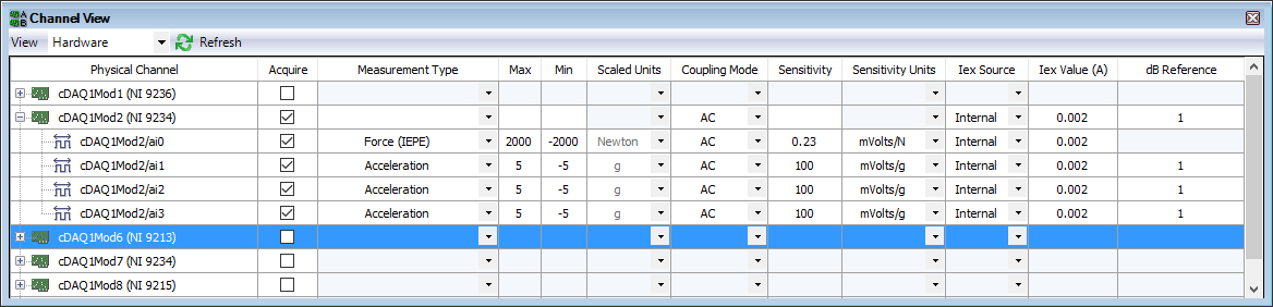
You can enable IEPE in SignalExpress. Here is a configuration for a single power hammer and three accelerometers a 9234-related.
You don't mention the model for accelerometers. They are also the IEPE sensors? If so, have what conditioning of signals you added before the 9205?
The Assistant Sound and Vibration (built on SignalExpress) contains an example of Impact Test. The Sound and Vibration Toolkit comes with a sample project for the impact test. With free evaluation period, go ahead and look at how one of these examples is implementing the configuration and the triggered acquisition.
-
generate a digital triggering out CH1 (low and high) for the USB-5133
Hello
I would like to generate a digital triggering on the USB 5133 CH1, is this possible? I tried with the PFI 1 successfully but the output is only 3.5 v and I need to 5V, because this trigger signal goes to a box of pulse generates a signal, which is received by the CH0 on the USB-5133. This configuration works on the 5102 OR but because of the treatment, I am obliged to try a new device.
Channel 0 and 1 are only entries then you will not be able to use them to generate a signal. All of our products current digitizer that are recommended for new designs use 3.3V CMOS logic levels for PFI lines in output mode. Your best bet to generate a digital triggering 5V would be to use an external buffer that can accept 3.3V CMOS levels as an input, but is under voltage of 5V. Here are some that might work for you, but there are many others: http://www.onsemi.com/PowerSolutions/product.do?id=M74VHC1GT126DT1G adding a buffer in line with the trigger signal will add delay, so you will need to ensure that it is acceptable for your application.
Hope this helps,
-Matt
-
Slope of digital triggering NI SCOPE
I have a problem, try to use a digital triggering with a USB-5133 digitizer. I use NO-scope (3.5) and C. My software doesn't seem to be able to change the slope of the trigger (using niScope_ConfigureTriggerDigital()). There is no problem if I use an analog trigger.
The problem is not related to my code. I see the same behavior with the NOR-SCOPE Soft Front Panel (version 2.9). In this application, if I connect the trigger PFI 1 entry and select digital triggering, then the selection of the slope has no effect. However, by selecting briefly "edge" trigger, change of slope in this mode and back to digital triggering, I find that the trigger is now working according to the slope in the edge, trigger mode.
Although niScope_ConfigureTriggerEdge() seems to work o.k. (using an analog input) and is not niScope_ConfigureTriggerDigital(), the following sequence does not provide a work around:
niScope_ConfigureTriggerEdge (...);
niScope_ConfigureTriggerDigital (...);
The entrance of IFP 1 seems OK, even though at the start I had been feeding it straight V CMOS 5 door. Adding a separator line at the entrance to the tensions between 0 and 2.8 V had no effect on the behavior.
Hello Bmetz,
It is a known problem that has been fixed in version 3.5.1 OR-scope. You can download and install the update through the page drivers and updates here:http://joule.ni.com/nidu/cds/fn/p/sn/n23:3465.40/lang/en
You will find a list of bug fixes in the readme, including the following:
123308: Fixed problem
with incompatible trigger when to change the edge of triggering on the NC
USB-5132/5133.Hope this helps,
Jennifer O.
Product Support Engineer: scanners high speed
-
buffer size and sync with the cDAQ 9188 problems and Visual Basic
Hi all, I have a cDAQ-9188 with 9235 for quarter bridge straing caliber acquisition module.
I would appreciate help to understand how synchronization and buffer.
I do not use LabView: I'm developing in Visual Basic, Visual Studio 2010.
I developed my app of the NI AcqStrainSample example. What I found in the order is:
-CreateStrainGageChannel
-ConfigureSampleClock
-create an AnalogMultiChannelReader
and
-Start the task
There is a timer in the VB application, once the task begun, that triggers the playback feature. This function uses:
-AnalogMultiChannelReader.ReadWaveform (- 1).
I have no problem with CreateStrainGageChannel, I put 8 channels and other settings.
Regarding the ConfigureSampleClock, I have some doubts. I want a continuous acquisition, then I put the internal rate, signal source 1000, continuous sample mode, I set the size buffer using the parameter "sampled by channel.
What I wonder is:
(1) can I put any kind of buffer size? That the limited hardware of the module (9235) or DAQ (9188)?
(2) can I read the buffer, let's say, once per second and read all samples stored in it?
(3) do I have to implement my own buffer for playback of data acquisition, or it is not necessary?
(4) because I don't want to lose packets: y at - it a timestamp index or a package, I can use to check for this?
Thank you very much for the help
Hi Roberto-
I will address each of your questions:
(1) can I put any kind of buffer size? That the limited hardware of the module (9235) or DAQ (9188)?
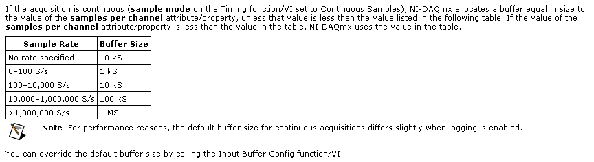
The samplesPerChannel parameter has different features according to the synchronization mode, you choose. If you choose finished samples the parameter samplesPerChannel determines how many sample clocks to generate and also determines the exact size to use. But if you use streaming samples, the samplesPerChannel and speed settings are used together to determine the size of the buffer, according to this excerpt from the reference help C DAQmx:
Note that this buffer is a buffer software host-side. There can be no impact on the material available on the cDAQ-9188 or NI 9235 buffers. These devices each have relatively small equipment pads and their firmware and the Driver NOR-DAQmx driver software transfer data device to automatically host and the most effective way possible. The buffer on the host side then holds the data until you call DAQmx Read or otherwise the input stream of service.
(2) can I read the buffer, let's say, once per second and read all samples stored in it?
Yes. You would achieve this by choosing a DAQmx Read size equal to the inverse of the sampling frequency (during 1 second data) or a multiple of that of the other playback times.
(3) do I have to implement my own buffer for playback of data acquisition, or it is not necessary?
No, you should not need to implement your own stamp. The DAQmx buffer on the host side will contain the data until you call the DAQmx Read function. If you want to read from this buffer less frequently you should consider increasing its size to avoid the overflow of this buffer. Which brings me to your next question...
(4) because I don't want to lose packets: y at - it a timestamp index or a package, I can use to check for this?
DAQmx will meet you if all packets are lost. The default behavior is to stop the flow of data and present an error if the buffer of the side host DAQmx overflows (if, for example, your application does not pick up samples of this buffer at a rate equal or faster than they are acquired, on average).
If, for any reason, you want to let DAQmx to ignore the conditions of saturation (perhaps, for example, if you want to sample continuously at a high rate but want only interested in retrieving the most recent subset of samples), you can use the DAQmxSetReadOverWrite property and set it to DAQmx_Val_OverwriteUnreadSamps.
I hope this helps.
-
No reconoce cDAQ-9188 via ethernet
Hola Amigos
Tengo el problema of Quebec able & Automation, me reconoce el chassis cDAQ-9188, pero no sus modulos he intentado todo lo, that will be replaced by Recomiendan en sesion http://digital.ni.com/public.nsf/allkb/DF65FCF0DD20D71686257949007ECAA7 pero esta no obtengo resultados positivos, alguien could orientarme...
Lo agradeceria muchisimo
PD: Editor lo me appears
Hi pomontty,
CDAQ networked systems requires a host booking, to avoid conflicts where multiple hosts on the network could attempt to access modules at the same time. For this reason, you don't have access to your modules until you have selected the reserve chassis from the top of the window in the right-click menu or MAX on your device in the devices tree. You cannot also self-test or reset the chassis when you have not booked, which is why you see the error that you have set.
-
digital triggering of stop/start of analog data acquisition
I want to use a signal from a digital line to start and stop analog data acquisition. The signal can change levels several times during a race of the VI so I have to start and stop several times data acquisition and store each session data in a different file.
I tried to play with the following screw: digital triggering of break, DigitalStartandStopTrigger and ContAcq_DigTrig. None of them doesn't seem to work for my configuration. I also do continuous data acquisition so I can't use a reference. I use PCI 6259 DAQ.
I used the "P0" pins rather than PFI pin on the grid BNC-2090. I know... stupid enough.
-
How many quadrature encoders may be read together with the cDAQ-9188 chassis?
We will record position periodically 8 engines (at the same time as we are to the corresponding samples entered analog). It seems that the 4 built-in counters limited chassis to 4 encoders. Is this correct? I am familiar with modules of counter PLC which manage high-speed counting, and then the CPU posts periodically to update the total values. This is how the NI 9401 card would work?
Hi jtrout,
You are right the 4 built-in counters than the cDAQ-9188 chassis 4 encoders. The following article deals with the use of the NI 9401 card for encoder measures: http://www.ni.com/tutorial/7109/en/.
-
LabVIEW 2010 with CDAQ-9188 and NI9205
Hello
I use the NI CDAQ 9188 with the Analog Input Module NI 9205. The specification of the NI 9205 module shows that there
16 channel differential channel, or simple 32 took end. I use the 'DAQ Assistance' in Labview to configure the
Module OR 9205. But it only allows me to select 8 differential channels. After I put the 8 channel, then the
Terminal configuration allows no differential inputs. It allows only to CSR or NRSE entered.
I'm doing something wrong? I just bought the camera to use for 16-channel differential reading.
Thank you
Bobby
Hello
It worked.
Thank you
Bobby
-
Networking the cDAQ-9188 - no 'network devices' Max
Hi all:
I have problems connecting my NI 9188 cDAQ via ethernet to my computer. MAX does not display it in his repertoire, or it displays "network devices". Based on the guide NOR offer, I don't know what else to do (I can't access the modules in a LabVIEW project which is my problem).
I used the tool online browser that seems to be the equivalent of MAX and works very well - I can see the IP address of the controller and it shows what chassis slots are used by what the map.
I tried manually inputing this IP in a remote system to the MAX, but that hasn't worked.
Any ideas on how I can networks controller on my computer so I can actually use in a LabVIEW project.
I have LabVIEW 2012 32 Bit. Would a student version be the cause of the problem?
Thank you very much.
cuaerospace wrote:
I am familiar with the method you describe, but I agree with all the power cycling to get some of these products to work. I had to do this several times with the cRIO. Any chance you could give a little more than a description step by step explcit of your approach? Thank you!
Good so here's what I did to try to reproduce and to have a step by step of what I had to do.
Firstly I have reset my cDAQ so that it would be if all goes well in the mode that yours is. To do this, I pressed the button to reset for 5 seconds then. I have also all my network devices defined to "Obtain an IP address automatically" in the IPv4 settings in my network connections.
After that, I start MAX.
Go to devices and Interfaces > network devices, then I right click and choose Find devices. It took a lot of time and the list was empty, but then I noticed that while he was always looking in this window, the MAX window showed my cDAQ-9188, who was a white device. There, he registered the IP address as 169.254.93.149. At this point if I went to the device to the MAX I saw where he sometimes States under network settings that no network adapters found.
So I closed MAX and open my "view network connections" in Windows, I just searched that term in the start menu. Then for my device properties, went to the IPv4 properties, set the IP address of 169.254.93.0 with 255.255.0.0 default gateway. It is, so I'm on the same subnet as the appliance.
I then restarted MAX now when I go to the device under devices, network and network settings I can set static IP and subnet is 255.255.0.0 10.10.10.100 then save. Then closed MAX.
Then I went back to my view network connections, the static value of what I really wanted is 10.10.10.0
MAX then launched. Find my device that is always white, click Add the device. And then all is good. I don't know if all these steps are necessary, and I don't know if there is an easier way, but it worked for me.
-
simulateneous of analog and digital triggering
Hello
I have an experience that is very similar to this announcement:
As in the display, I need trigger out of logic AND low frequency (3 Hz) and a signal of high frequency (100 Hz). However, my experience is different because my low-frequency signal is an analog of entry (AI0) and I need experience to trigger off each edge of the signal change high frequency, while the analog input is high. To do this, I created a trigger to HAVE that starts a counter whose state high and low are similar to that of my analog input signal. I then export the output event from the meter to a port (PFI8) and pass this signal and the other signal high frequency through a door AND as in the posting linked above.
So far, everything works. I've included a VI that is just this part.
However, I then connect the output of this gate AND a PFI0 port and use it as a digital triggering to read an AI0, 1 channel. When I perform this final step, my whole system stops working, but gives no error. To troubleshoot, I measured the output of the meter to the port of PFI8 has stopped working and the port of PFI8 remains in the low state. For some reason any when I add the channel HAVE additional (AI0 or AI1, whatever) with digital trigger (PFI0), everything grinds to stop. I have also included the VI for this case.
Any ideas?
Thank you very much!
Hi Jared,
I use indeed a door AND external as described in the thread. Further research actually led me to discover that "you can't have two analog input tasks at the same time" of this thread:
So I had to build a circuit to convert my analog signal into TTL signals (for the release). I then AND'ed the two signals in the same was as described in the thread mentioned above.
-Clinton
-
the cDAQ-9188 discovery method?
I have a cDAQ-9188 I prepare for use by customers in the area. These customers tend to forget IP addresses, and I would like to add something to my request to help. Something installed "NI Network Browser" on my development machine. I suspect it was DAQmx 9.2.2. This browser appears to be a shortcut to a web page of Silverlight being served off port 59648. The browser does a good job to list the chassis on the network, and I would like to know if there is a way to make this work in LabVIEW. It uses UDP or something?
I know that the standard method would be to ask clients to use the network browser, but I'll try match the SCXI-1600 user experience where you just plug in and it appears. I try to avoid making them run MAX or a browser or anything but my request. I know that I can avoid the MAC with the VI DAQmx step add network device, but he wants an IP address for an entry.
Thank you
Dan
Hi Dan,.
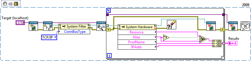
The API for the system setup OR was released earlier this year and aims to provide developers the ability to integrate MAX features into their distributed LabVIEW applications. The following code uses the API and should be a good starting point for what you need to do:
If you have any questions or encounter any problems do not hesitate to post back!
Best regards
-
Multifrequency 9223 9215 sync and 9213 in cdaq 9188
Hello
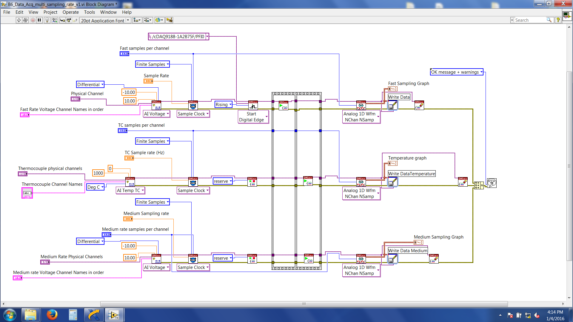
I'm trying to synchronize three different modules (NI 9223 and NI 9215 NI9213) every acquisition given to various higher sampling frequencies (e.g. 9223 = 1000 hz, 9215 = 100 Hz and 9215 = 2 hz) and write files to separate data for my task. I am using a cDAQ-9188 ethernet and all modules are in the same chassis. There is an external trigger (which comes from an external source) to start acquiring data which are wired connected to the PFI0 channel in the chassis. What I want to do is: whenever the trigger is high, acquire 10seconds of data according to different sampling frequencies high above and write in separate data files. I followed the procedure referred to in the http://www.ni.com/tutorial/5376/en/
Here's a snapshot of the block diagram
Now, the problem I am facing is the 'average frequency (NI 9215) data' and 'data of Thermocouple (NI 9213)' are acquired and written immediately after that I have start the labview program. Fast speed data (NI 9223) are not written, and wait for the trigger signal. And then it throws an error 200284. If I do just a finished sample rate on NI 9223 alone (without adding/attempt at sync with other modules) with expectation of release it works without any problem.
LabVIEW files are attached.
Suggestions very much appreciated and you wish all happy new year.
Thank you
Roy
Hi Roy,
'average frequency data (NI 9215)' and '(NI 9213) Thermocouple data' is acquired and written immediately after that I have start the labview program.
Yes.
You forgot to set a trigger to start these DAQmx tasks!
And then it throws an error 200284.
The description of the error says something like "use a higher timeout value. Have you tried that?
Maybe you are looking for
-
Satellite P300 PSPC4A - BIOS no updates required for Win 7?
I have a Satellite P300 (PSPC4A-03P01P)Currently 2 hard drives, both are partitioned.Disc 1 - C and DDisc 2 - F and GCurrent operating system on the C drive is OEM Vista 32-bit HPBIOS version is V4.20. 05/01/09 I want to upgrade the Win - 7 HP 64-bit
-
While you write that this make me the beachball, so sad this exceptional machine that has worked without problem through many years came to a full stop after the upgrade People here are my BEING check copy please check out EtreCheck version: 2.9.6 (2
-
HP G62: Can not access the keys on blue character on PC HP G62
I'm unable to access the blue characters on the keyboard, despite trying to hold control, shift and shift to the right at the same time. Could someone tell me please how to do this? Thank you
-
Permanently remove Microsoft games in XP Home edition?
I'm talking Internet Checkers, solitaire, etc. I don't want to say ununstall it as components of Windows, I mean it permanently remove it from my hard drive. Thank you very much!
-
Hi, I assume that after an automatic update, my media player has recently begun opening in playing instead of the library, where it is used to. I did a ton of research and it seems most people want to open as read in class, but I did not. Is it possi