Center frequency.
Hello world. Can you please help me with assignment on bandpass filter.
Open the attachment you will find the assignment and the formulas to work with.
Thanks Ed.
Ed,
We do homework for you. As well as being unethical, you don't learn anything.
If you have specific questions about LabVIEW, we can help. For example (and as a tip) the range function & force can be changed so that the upper or lower limit is included or excluded by context-clicking on the icon.
Lynn
Tags: NI Software
Similar Questions
-
Center frequency and Span for ESA Spectrum Analyzer
Hi all
I ask a silly question but I've tried several things didn't work so ask you all.
I need to set the Analyzer of spectrum as follows:
RBW: 10 kHz
Scanning: AUto
Length of 2400 Mhz
REF level-40 dBm
Track 1: view
Track 2: max Hold
Tarce 3: min hold
R HAND CENTER freq 65850kHz
But when I run my program all values are preparing ex CENTER FREQ it always defined as 1200 Mhz.
I don't know is there any adjustment which automated Center freq come always supply for half the interval of?
If someone can tell me the solution for this...
Thank you very much
Hi all...
Got the difference between Center freq and span solution is too big... If its not to accept...
Now, I get the correct values... Due to the beginning of the range huge freq spectrum was below of beach... That was the problem...
Thank you all...
-
How to operate continuously the ' frequency with digitizer step-down converter external vi "?
Hello
I use SMU-5663 on SMU-1075 chassis. My goal is to use "step-down with digitizer external .vi" in order to run the SMU-6901 frequency continuous step-down converter. To do this, I added a while loop to the provided sample (see file attachment). The problem is that the while loop does not change; the program stops as soon as its launch.
Is there anyone who can help me with this you problem?Hello
The 'get frequency response' VI aims to help correct the answer of the step-down in the acquired data. The response of the step-down changes only with frequency and reference level. In your VI, you are in a loop when you call 'Get frequency response' but do not change the frequency or level baseline for the release of the VI will not change.
To use the external digitizer, you want to adjust the center frequency and level in DAMA reference, read the frequency response and frequency step-down converter win in DAMA, to acquire data starting from the external digitizer and correct using the frequency response of the step-down, and win. You can loop through the acquisition and treatment portions until you change the central frequency or reference level.
-
Wavelet transform scalogram frequency scale
I've read all the posts on this topic and found no answers, that would be useful for me. However, I found a formula to convert pseudo frequency scale. My client wants scalogram with the y-axis as the frequency of the signal and x-axis as of the time of the signal. I tried to use the multiplier of the graphical indicator property but I can't get the correct values of the frequency in the Y axis. The formula I use is f = Fw / (dt * s) where f is the frequency of nickname, Fw is a center frequency of the used Wavelet (Morlet), dt is sampling the signal time and scale. FW is 0,8125 Hz (at least that is what Matlab tells me), dt is 0.01 s (100 Hz aqusition), the scales are numbers from 1 to 128. Basically I wan't to know how to convert the graphical indicator scale. I drew the correct chart in Matlab, but I must do the same in Labview. I have attached two screenshots.
Hello
Well, you can use the property nodes in order to change the scale.
If you right-click Scalogram, create, property node and you choose the multiplier and offset.
You simply calculate the offset, it is about 80,61 and the multiplier is on-0,63. And you calculate scale of nickname.
The use of knots of property you can change a large number of parameters for the scalogram.
Hope that solves your problem.
Kind regards
Ion R.
P.S. As LabVIEW is an engineering environment, it is not so obvious how you can reverse time :-) (or frequency)
-
external frequency step-down converter
Hello
1. I have a digitizer 5142 with a resolution of 14 (16) bit. can I change this rate of 8-bit scanning, or can I get a signal to 8 bits using 5142 I
think I can using neither scope config. If yes also means I increased the speed of 200MBS 100MBS (since I am only
using 8-bit scanning). increases the speed of transfer of the data from my memory shipped to hardisk only or both are applicable
2 - I read this specification 5142 when I stumbled upon two things that I surrounded as JPG attachments
a. filter anit-alisasing has a bandwidth of 40 Mhz, and default 5142 uses what it means. Can I use
some other external down converter instead of 5600 and which can acqiure 40 Mhz bandwidth at any center frequency and I can feed to
5142 to get digitized and writre a file on my disk. .i can't use DAMA since I use a step-down external frequency converter. How using or
scope/tuner vi.
(b) the other is true flat bandwidth = 0.4 * rate and bandwidth flat complex sample = 0.8 * sampling frequency that we mean by these two.
Concerning
MADD
Hi malala.
1. correct me if I'm wrong. Insofar as I have defended frequency translation means that if I have acquired a signal at 50 MHZ with a 40 MHZ Bandwidth (F_high = 70 Mhz and F_low = 30 Mhz). My frequency step-down converter. If I select the option enable translation frequency and frequency set to 20 MHZ (option to activate with the SDC thus) signal that I have gained is now translated to 20 MHz (C.F), the maximum frequency to 40 Mhz and Minimum to 0 Mhz. Is it so? If this is correct, then I think that my Ghost will meet the requirement of the spectrum of nyquist and won't be mitigated...
Not quite fact-frequency translation used to take your signal of a certain frequency IF complex base band (centered around 0 Hz). If you set your frequency of 20 MHz, 20 MHz will tune to your NCO and you will acquire some bandwidth, based on IQ rates, around this central frequency. For example, if you used 20 MHz bandwidth (rate of IQ = 25. MECH / s) and a center frequency of 20 MHz, get you 10 MHz to 30 MHz of frequency and translate this to baseband. Now you have your frequency content at +/-10 MHz.
To do what you seem to want to do, you must set your frequency to 50 MHz as well as your IQ rate to 1.25xBW = 50 MECH. / s. This will mean your 40 MHz BW from 50 MHz to complex baseband.
2. also mention that I can put this decimation is property invoke node or filter specifications.
Decimation is another property of the OSP and the mechanism of the clock. Your decimation is defined by your IQ rate compared to your time base sample clock. For example, by default, we use a time base 100 MECH. / s for the 5142. If I put my IQ rate 2 MECH. / s, I will use a factor of the decimation of 50. Our table of decimation emphasises, however, that, in the range of 12 to 4 096, we can only use decimation integers that are multiples of four. So, we will eventually be forced in this case to 48 and a sampling rate of 2.0833 MECH. / s. You can then perform resampling to 2 MECH. / s in the software.
3 - something else enable and disable the noise/anti-aliasing filter. Combination of maximum frequency of niscope configuration characteristic.vi. If I put it in noise filter 20 Mhz is on now and when I started 35 Mhz filter anti-aliasing is enabled. Is it so?
That's right - your maximum frequency setting to be in one of these filters will allow this way. If I put a maximum frequency of 19 MHz, the filter is activated. If I put a max of 30 MHz frequency, the Anti-aliasing filter is enabled. 0 will default, and -1 will allow full BW.
Kind regards
-
USRP 2920 if after joint bottom (after the MIXING table)?
Salvation _ or
the NI USRP-2920 is a good product I use it to train students on some applications
I read manual for this product its especially usfel and covering a large part of the specs of the device, BUT "nothing mentioned about.
Central frequency (IF).
"to clarify my question" when the signal down mixed RF is it wil be centered arround fixed frequency for demodulation processs "its about 12.5 MHz in one of the device NOT USRP"
What is the center frequency of the baseband signal after mixed down?
I wish I can explain my problem, iam waiting for your answer, answer or tell me you want more explanation on what I want now...
Thank youIt is a direct down conversion device. RF is mixed with the baseband quadrature I and Q. There is not SO.
-
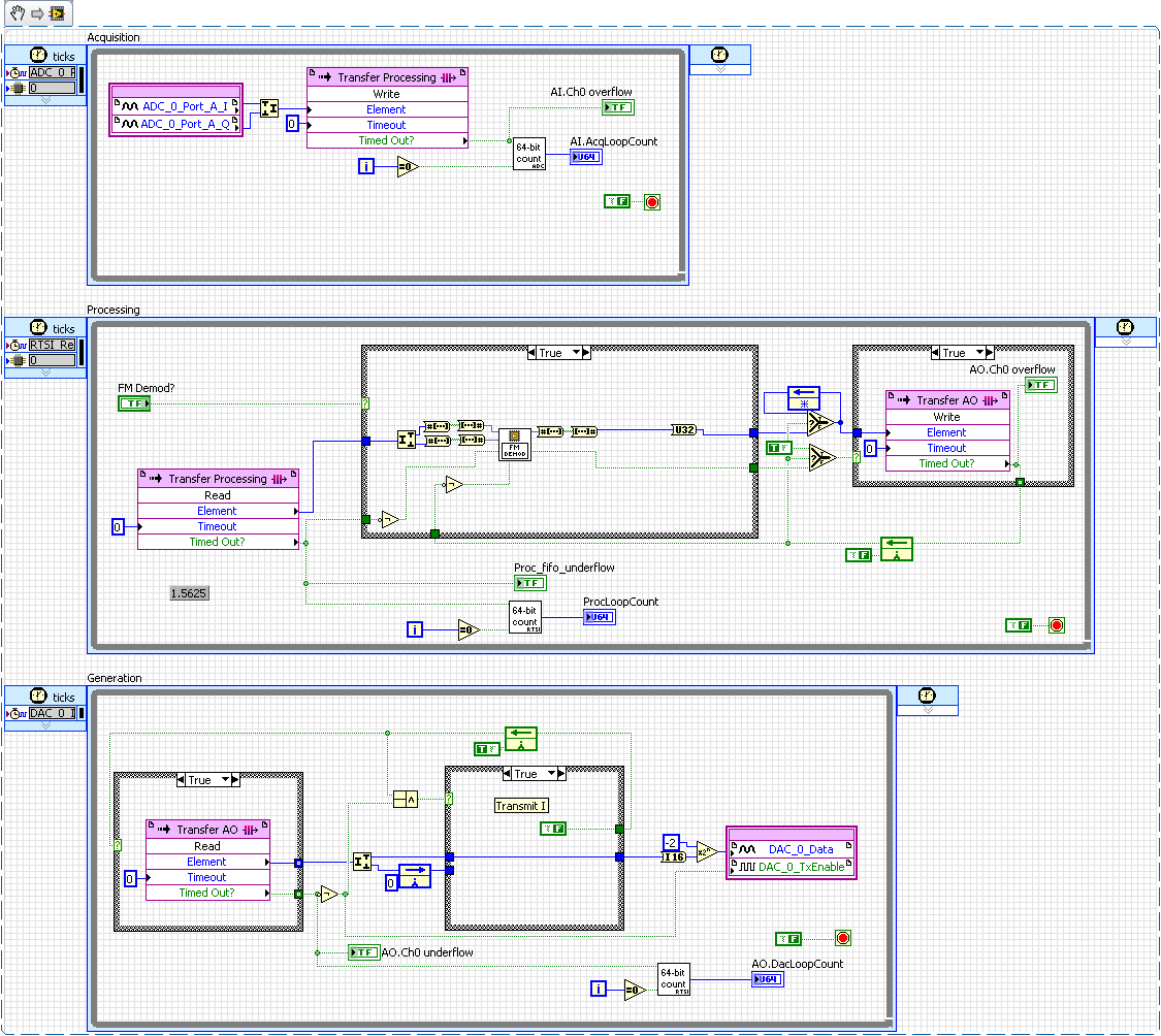
Hello
I was the object of a change slowly
the example of FM-Demod 5641R, RF communication, in a library
FM-Demod/Regen for example. I mainly want to use the 5641R as one
retransmitter with treatment. I have successfully used the 5641R as one
retransmitter without treatment, but I noticed that the retransmission
a Demoded-FM signal is not as expected. Mainly because the output of
the core of FM - Demod IP is a true value and the D/A on the 5641R is
configured for quadrature I / Q mode. So, I have to add another
processing loop in order to recreate the IQ data and if then...? I am
familiar with the concept of QI and how to build it but I'm pretty
new development of FPGA as a Point fixed so I couldn't
find a way to do it on the FPGA. Y at - it sort of 'MT '.
Upconvert the baseband to the IQ' block for the FPGA?Right away
I get essentially double spectrum when the regeneration of the
FM-demoded samples. For example, a signal of 4fsk becomes 2-tone mirror
on each side of the center frequency of YEW instead of 4 independent
tones.I have attached a code snippet below.
Kind regards
Tim
S.
-
RFmx and FetchSpectrum using Python
Hello
I'm trying to use RFmx through Python.NET. The code works until I have try to catch the spectrum using FetchSpectrum():
# create the name of the variable before you pass it to the method .NET
spectrum = RFmxSpecAnMXSpectrum# This does not work!
specAn.Spectrum.Results.FetchSpectrum (", timeout, spectrum)Here's the complete code:
import clr
import sys# location of the assemblies
assy_path = r'C:\Program files (x 86) \National Instruments\MeasurementStudioVS2010\DotNET\Assemblies\Current'
sys. Path.Append (assy_path)CLR. AddReference ("NationalInstruments.RFmx.SpecAnMX.Fx40")
CLR. AddReference ("NationalInstruments.RFmx.InstrMX.Fx40")from NationalInstruments import *.
from NationalInstruments.RFmx.InstrMX import *.
from NationalInstruments.RFmx.SpecAnMX import *.# The VSA settings
resourceName = "5606_slave."
centerFrequency = 10.0e9 # Hz
referenceLevel = - 10 # dBm
externalAttenuation = 0.00 # dB
Timeout = 10 seconds #.
span = 1.0e + 6 # Hz
RBW = 100e3
averagingCount = 10instrSession = RFmxInstrMX(resourceName, '')
# configuration VSA
rbwAuto = RFmxSpecAnMXSpectrumRbwAutoBandwidth.True
rbwFilterType = RFmxSpecAnMXSpectrumRbwFilterType.Gaussian
averagingEnabled = RFmxSpecAnMXSpectrumAveragingEnabled.False
averagingType = RFmxSpecAnMXSpectrumAveragingType.Rms
#specAn = instrSession.GetSpecAnSignalConfiguration ();
specAn = RFmxSpecAnMXExtension.GetSpecAnSignalConfiguration (instrSession)
specAn.ConfigureRF('',centerFrequency,referenceLevel,externalAttenuation)
specAn.Spectrum.Configuration.ConfigureSpan('', span)
specAn.Spectrum.Configuration.ConfigureRbwFilter (", rbwAuto, rbw, rbwFilterType)
specAn.Spectrum.Configuration.ConfigureAveraging (", averagingEnabled, averagingCount, averagingType)
specAn.SelectMeasurements (", RFmxSpecAnMXMeasurementTypes.Spectrum, bool ())
specAn.Commit ("")# run acquisition
specAn.Initiate('','')# find the peak power in the spectrum
_, pkAmp, pkFreq, freqRes = specAn.Spectrum.Results.FetchMeasurement (", timeout, float (), float (), float ())
Print "peak power: dBm {:0.2f} to {:0.6f} GHz'.format(pkAmp,pkFreq*1e-9)}}""""
A .NET method may require user pass the variable name that it wishes to
change as an argument. Python is not compatible "pass by reference", but the
the variable name must exist in python, before he can be handed over to the .NET method.
The .NET method will simply point to the new instance.http://nbviewer.IPython.org/GitHub/jonnojohnson/Agilent/BLOB/master/Python_Automation/Python_Automation.ipynb
"""# create the name of the variable before you pass it to the method .NET
spectrum = RFmxSpecAnMXSpectrum# This does not work!
specAn.Spectrum.Results.FetchSpectrum (", timeout, spectrum)instrSession.Close)
Here is the error:
Traceback (most recent call changed):
File "
", line 3, in
specAn.Spectrum.Results.FetchSpectrum ("", timeout, spectrum)ArgumentException: Object of type 'System.RuntimeType' cannot be converted to type ' NationalInstruments.Spectrum'1 [System.Single] & ".
at System.RuntimeType.TryChangeType (Object value, Binder binder, CultureInfo culture, Boolean needsSpecialCast)
at System.Reflection.MethodBase.CheckArguments (Object [] parameters, Binder binder, BindingFlags invokeAttr, CultureInfo culture, sig Signature)
at System.Reflection.RuntimeMethodInfo.InvokeArgumentsCheck (Object obj, BindingFlags invokeAttr, Binder binder, Object [] parameters, CultureInfo culture)
at System.Reflection.RuntimeMethodInfo.Invoke (Object obj, BindingFlags invokeAttr, Binder binder, Object [] parameters, CultureInfo culture)
to Python.Runtime.MethodBinder.Invoke (inst IntPtr, IntPtr args, kw, MethodBase info, methodinfo MethodInfo [] IntPtr)Any ideas?
Ah! That's about all. Here's what worked:
spectrum = NationalInstruments.Spectrum [System.Single] (0)

_, spectrum is specAn.Spectrum.Results.FetchSpectrum('',timeout,spectrum)
Here is the result and the final code for future reference:
import clr

import sys

Import os

import matplotlib.pyplot as plt
Import numpy as np# To Program Files Windows environment variable
Program_Files = os.environ ['ProgramFiles (x 86) ""]
assy_path = os.path.join (program_files,
"National Instruments",.
"MeasurementStudioVS2010,"
"DotNET"
"Assemblies."
'Current')sys. Path.Append (assy_path)
CLR. AddReference ("NationalInstruments.Common")
CLR. AddReference ("NationalInstruments.RFmx.SpecAnMX.Fx40")
CLR. AddReference ("NationalInstruments.RFmx.InstrMX.Fx40")from NationalInstruments.RFmx.InstrMX import *.
from NationalInstruments.RFmx.SpecAnMX import *.
import NationalInstruments
Import System# The VSA settings
resourceName = "5606_slave."
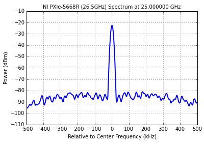
centerFrequency = 25.0e9 # Hz
referenceLevel = #-10 dBm
externalAttenuation = # 0.00 dB
Timeout = 10 # seconds
span = 1.0e + 6 # Hz
RBW = 100e3 # Hz
averagingCount = 10instrSession = RFmxInstrMX(resourceName, '')
# Get the model number
_, Model = instrSession.GetInstrumentModel (", Str())# configuration VSA
rbwAuto = RFmxSpecAnMXSpectrumRbwAutoBandwidth.True
rbwFilterType = RFmxSpecAnMXSpectrumRbwFilterType.Gaussian
averagingEnabled = RFmxSpecAnMXSpectrumAveragingEnabled.False
averagingType = RFmxSpecAnMXSpectrumAveragingType.Rms
specAn = RFmxSpecAnMXExtension.GetSpecAnSignalConfiguration (instrSession)
specAn.ConfigureRF('',centerFrequency,referenceLevel,externalAttenuation)
specAn.Spectrum.Configuration.ConfigureSpan('', span)
specAn.Spectrum.Configuration.ConfigureRbwFilter (", rbwAuto, rbw, rbwFilterType)
specAn.Spectrum.Configuration.ConfigureAveraging (", averagingEnabled, averagingCount, averagingType)
specAn.SelectMeasurements (", RFmxSpecAnMXMeasurementTypes.Spectrum, bool ())
specAn.Commit ("")# run acquisition
specAn.Initiate('','')# get x data
spectrum = NationalInstruments.Spectrum [System.Single] (0)
_, spectrum is specAn.Spectrum.Results.FetchSpectrum('',timeout,spectrum)# get data
analogwaveform = NationalInstruments.AnalogWaveform [System.Single] (0)
_, analogwaveform is specAn.Spectrum.Results.FetchPowerTrace('',timeout,analogwaveform)close a session #.
instrSession.Close)# calculate the frequency and power
startFrequency = spectrum. StartFrequency
frequencyIncrement = spectrum. FrequencyIncrement
sampleCount = spectrum. SampleCount
stopFrequency = startFrequency + frequencyIncrement *(sampleCount+1)
freqArray = np.linspace (startFrequency, stopFrequency, sampleCount)
current = list (analogwaveform. GetRawData())results of tracking #.
XScale = 1e-3
PLT. Plot ((freqArray-centerFrequency) * XScale, Power, LineWidth = 2.0)
#plt.ylim(referenceLevel-100.,referenceLevel)
PLT.yticks (NP.linspace(referenceLevel-100.,referenceLevel,11))
PLT.xticks(NP.linspace(-span,span,11)/2*XScale)
PLT. XLIM(-span/2*XScale,span/2*XScale)
PLT. Grid (true)
PLT.xlabel (' from center frequency (kHz) ")
PLT.ylabel ('Power (dBm) ")
PLT.title ("{} {:0.6f} GHz spectrum".format(model,centerFrequency*1e-9), fontsize = 'medium')
PLT. Show() -
Compatibility of boards of daughter BasicTx and BasicRx with USRP2920 and LabView
I want to know that girls BasicTx and Rx cards Ettus research base are compatible with USRP2920 and Labview or not.
These cards also supports variable gain or not? Please confirm
Thank you
JK
They will work, but you must use property nodes to configure them. No is no LO so ther is no center frequency setting. I and Q are separate channels so you must separate them and treat them as such. There are no gain as the boards primarily provide access to the ADC.
-
Is it possible to build the filter of the Octave in LV?
Hello brains
I have a request for application of noise measurement is to filter around a few select frequencies at 1 / oct bandwidth.
I know it's available in the kit of audio tools and vibrations, but add such an expensive suite of tools for the project is not feasible for such a small feature.
I'm not a filtering guru. Y at - there someone here who can point me in the direction of how to implement a simple filter with bandwidth of 1 oct to a fixed frequency? Thank you in advance.
The environment is LV 2012 on windows.
In the range of signal processing, there are a butterworth filter. Place it just type bandpass and pass it a high frequency of 1.414 * center frequency and a low frequency of the frequency of 0.707*.
You can try the other types filter tchebyshev etc if you want to play with the responses of different phase.
-
initiation of an analog signal noise
Here's the idea (the concept is available in commercial software) - to remove the background noise of an audio event, acquire a small sample pre-event, and do a FFT to discover the strength of the signal in multiple bands; It's the characterization of noise. Then set a threshold for each a little higher than the intensity of the noise signal. It is then applied to the 'event' to each frequency band - if the signal for the event does not exceed the threshold of this band, which is not part of the event, but just background noise. This I did, my question is how to better implement the filter in LabVIEW - I think both approaches, (a) filter in the frequency domain (should be easy), but can only be returned in audio in the time domain? or (b) the audio sample run through a series of band pass filter beginning by stripping the lower frequencies and working to the highest and what remains is the audio event with any other deleted. Whoever did this in LabVIEW?
Or of your approaches can be used in principle. In practice you can't get as good performance as you want.
With both methods a few time delay between the audio input and audio output will exist. How much delay you can tolerate?
(A) to two FFT. One of the pre-event segment. The other is the segment of the event. If the sgements are of different lengths, df will be different and this will make the rest of the complicated treatment. The shorter segment with zeros to fill is the easiest way to match the DSV, but will present amplitude errors. After resetting in the case where the bins below thresholds segment FFT, do the inverse FFT. Be sure to use complex numbers on all frequency domain calculations to avoid losing the key stage information.
(B) you will have to deal with transient responses and delays of the filters. Each filter with different center frequency and bandwidth will have a different response and delay. Compensate for these effects can be very inconvenient. With continuous data spikes fade, but for your process based on events, it can be a viable solution.
Lynn
-
Get information from the low level of the Subvi ni5660
A quick explanation of the problem: I need to create several VI just to return a value of the PXI-5660 (ex: Center frequency, Span, etc.) while the entries are only a "VISA" and one "error in.»
Detailed explanation of problem: I need to create multiple VI that the properties 'Set' or 'Get' of the PXI-5660 module (ex: the Central frequency value, get frequency, etc...). Each VI must have a VISA in/out and in/out Error, but the only other present in/out should be the property of game/called. Global variables are not allowed.
One of the biggest problems for me is that ni5660 drivers do not contain a property node. I managed to (apparently) set some of the properties by feeding only a single entry in the icon 'configure ni5660 for spectrum', but the only tool that seems to be able to output all information is the icon «MT get Attributes» The release of 'MT get Attributes' does not contain many of the properties that I need good output.
I tried to use the icon 'MT get Attributes' linked to "ungroup by name" which has the value "handle receiver.handles.niScope" which feeds on the reference to a property niScope node, hoping that I would be able to obtain information through the niScope 5660 (it seems that ni5660 software uses the niScope on a lower level software ", correct me if I'm wrong). This VI finished, when put online with the 'ni5660 Initialize.vi' and ' ni5660 Close.vi, ' returned the error (-1074135028) with the explanation 'ID attribute not recognized.' "" (The error occurred on the property node in the Subvi "Get the Central frequency")
The goal is to make the action of PXI chassis similar to a HP8563E Spectrum Analyzer. With this in mind, the list of attributes that I will need in the end to set and get (the separate VI) are the following: Center frequency, Span, window, number of Points, resolution bandwidth, level of reference, mitigation and time sweep.
I apologize for my (very probably) simple question, but endless (I only started programming in LabVIEW there about 2 weeks). If someone would be able to point me in how to make apparently PXI-5660 current property settings from thin air, I would be very grateful. If more information or details are needed, feel free to ask.
Thank you
zdunn wrote:
....
but unfortunately, I'm still at a loss, how to create a VI that "calls" that same property back and the fate, while using only 'VISA In' and 'In Error' as inputs.
Located on how silly that statement. You want to create a function where (for example) you want to set the resolution bandwidth and do not want to pass as a parameter the name of the instrument. You have created the programming language that is able to read minds?
You can use a function where you can pass a parameter in (or use a function that retrieves a parameter) or do nothing at all with the instrument. It is more complicated than that.
There are tutorials available that can help yu with LabVIEW to learn, but I think that there are certain fundamentals means.
Edit: Sorry, I may have misunderstood. to query does not require an entry but I don't understand what you want to query. The parameters of the instrument are all under control stripped - a program you or any other writing. Unlike a GPIB instrument, there is no one '?' command to read a rear frame. It is assumed that you know how the instrument has been configured in the first place.
-
My ABC (Cincinnati) local affiliate, WCPO, today broadcasting on Channel VHF 9 - 09/12/2010. They are now on a UHF frequency radio. I don't know what channel/frequency. When this switch occurred, Media Center has started to display the message "No TV signal". Apparently, the Media Center picks up information of the station from a central location and not be notified of this change.
I have downloaded the latest Media Center Guide, turn the computer off and then restart Vista. This did not help.
Went to 'Task'-> 'Settings'-> 'Set Up TV Signal' this morning (9:30 EST, 11/12/2010) and went into the channel configuration process. When I finished, WCPO Channel 9 has been available again. Here is the line from the file atscchannel.xml for WCPO it appears now: -
Generation of frequency hopping signals
I work with 5661 + 5671.
I want to generate the signal with 5671 to frequency hopping. The frequency band is 2400-2500 MHz, and the jump rate is a jump by image (1.024ms) or 976 hop per second.I also need to be able to test the recurrent signal with DAMA 5661.
We can run these jumps tests with 5671 5661 +?
Thank you
Chen
Hi Chen,
What is a Bluetooth application?
The 5661 and 5671 have the instantaneous bandwidth of 20 MHz. In addition, the setting time of change Center RF bandwidth of 20 MHz for both devices is about 30 ms.
It would be possible to retune, or frequency hopping, in a band of 20 MHz to 1,024 ms (by retune embedded signal processors), but given that the devices cannot cover the entire 100 MHz of the region ISM 2.4 GHz band if frequency-hopping spread over more than 20 MHz, it would be necessary at some point in which case the setting time prohibit it to retune the Central frequency of the devices.
Kind regards
Andy Hinde
National Instruments
-
I read in the audio data, getting the FFT and display data - frequency Vs... Greatness. I wish to address some bands to zero.
The data type of output after the FFT (PS/PSD (VI) is a cluster of 3 elements, fo, df and size (table 1). I have unbundled the output of the PS/PSD VI by name.
Then, I'm putting some items in the table of size 1 d to zero.
The problem...
I can't seem to re - create the cluster of 3 elements, fo, df and magnitude such that I can graph the result.
Help is very appreciated!
A simple bundle is all you need. Use "Group by name" and plug the old cluster on the top center. This will fill the element names. Now select the entrance of greatness and the new wire size table.
All other components (f0, df) will be retained. See the image.

Maybe you are looking for
-
40TL938G Toshiba: Toshiba Places - can not open the app "Brain Trainer".
Hi people, Did someone has the same problem, when when I try to open the brain train space edition on toshiba sets up game, he stuck on the boot screen and does not open. Does anyone have a tip? Thank you.
-
Satellite Pro A100: Why can not connect Internet with the net card
I can't connet Internet whith this net card, but I always connect it with a wireless network card
-
Satellite P750 - Dragon Age II breaks down
Hey I looked all over the Internet for similar problems, but I can't seem to fix it on my pc. I have a nVidia GeForce GT 540 M 2 GB graphics card and I ve just installed the latest version of nVidia 275.33 drivers. My computer is a Satellite P750, In
-
I have 13 updates to visual c ++ 2005 SP1 KB2538242
I get updates of visual C ++ 2005 service pack 1 for the last three days. Restart the computer after installation and when I reboot there is another update of the same type. all the updates install. How many updates are there.
-
I cand with error code 0 x 4001100200001005?
Error code 0 x 4001100200001005 I started to run recovery of the DVD that I bought from HP. During the process of recovery of the error code 0 x 4001100200001005 appeared, and then my computer went dead. I can restart and when happens the screen hp I