initiation of an analog signal noise
Here's the idea (the concept is available in commercial software) - to remove the background noise of an audio event, acquire a small sample pre-event, and do a FFT to discover the strength of the signal in multiple bands; It's the characterization of noise. Then set a threshold for each a little higher than the intensity of the noise signal. It is then applied to the 'event' to each frequency band - if the signal for the event does not exceed the threshold of this band, which is not part of the event, but just background noise. This I did, my question is how to better implement the filter in LabVIEW - I think both approaches, (a) filter in the frequency domain (should be easy), but can only be returned in audio in the time domain? or (b) the audio sample run through a series of band pass filter beginning by stripping the lower frequencies and working to the highest and what remains is the audio event with any other deleted. Whoever did this in LabVIEW?
Or of your approaches can be used in principle. In practice you can't get as good performance as you want.
With both methods a few time delay between the audio input and audio output will exist. How much delay you can tolerate?
(A) to two FFT. One of the pre-event segment. The other is the segment of the event. If the sgements are of different lengths, df will be different and this will make the rest of the complicated treatment. The shorter segment with zeros to fill is the easiest way to match the DSV, but will present amplitude errors. After resetting in the case where the bins below thresholds segment FFT, do the inverse FFT. Be sure to use complex numbers on all frequency domain calculations to avoid losing the key stage information.
(B) you will have to deal with transient responses and delays of the filters. Each filter with different center frequency and bandwidth will have a different response and delay. Compensate for these effects can be very inconvenient. With continuous data spikes fade, but for your process based on events, it can be a viable solution.
Lynn
Tags: NI Software
Similar Questions
-
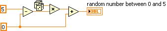
How to generate analog signals?
Hi all
I'm trying to generate analog signals to simulate the position of the valve. I also want to simulate the position of the valve 0 - 5V (analog signal). I've implemented the numeric position of the valve by using the toggle switches, but I want to implement analog signals.
You can help.
Thank you
You can just use a random number generator.
Since you have no generator hardware signals of NOR, I'm not sure why you are posting to this Board. Generic questions of LabVIEW. Post to this Board.
-
How to calculate the signal / noise from the graph?
In my current project, I read a periphera voltage signal. the signal lead noise even after filtering. So, to identify the necessary data, I averaged the signal.
I have attached the file with an image of graphics. In this graph, the recorded data are drawn black and medium online graph is plotted in red. Now, I have to calculate the ratio of signal to noise to specify with these peak values. How to do?
As the signal passes through zero, be careful in the way you set the signal / noise. For sinusoidal signals, that ratio is defined as the RMS value of the noise (the signal with the desired sinusoidal signal deleted) divided by the effective value of sinusoidal component.
First of all I would like to subtract the average value of the raw signal. The difference is the noise. You can set the signal / noise. A RMS calculation might work. If you have a mathematical model for the desired signal, a fitting for this model can be useful too.
Lynn
-
Hi all
I'm still new to LabVIEW, but I played a little enough to create a simple analog signal generator. Product signals appear staircased when displayed on an oscilloscope, but are smooth, when I read the signals in an entry (as shown by the graph on the waveform) analog. How can I change my program settings so that I can see this staircased signal?
I run LabVIEW 2010 and use a data USB X Series multifunction acquisition.
Thank you
-Olivier
-
How to create an analog signal of a text or a binary file?
I'm trying out an analog signal of a file on a map of NOR-DAQ 6251 with labview 8.5. I found examples on the construction of a waveform, but I'm stuck at how read a text file and do a 1 d table to enter my amplitudes in the buildwaveform.vi and I can't find all the information on how to do it. Help or direction is appreciated.
Thank you
David
What if all you want in the file corresponds to the values of Y, then a text file with a value on each line can be read. Read from a usable spreadsheet file. It will return a 2D you can then use array index to get a column or if you select Transpose, the array returned by 1 d would be used.
If you want to create an example, use a 1-d array constant in a VI and pass it to the writing on a spreadsheet file.
-
How can I use my PXI-6115 meter analog signal trigger to generate pulses of frequency
I work on a PXI-6115 DAQ card and want to using the analog signal to trigger the counter it's generating frequency pulses. The manual says the analog trigger is supported, but I can't use an analog signal to trigger the start of work, in the test, I use the counter 0 to generate pulses and use the signal input port analog trigger PFI 0, can someone tell me what it is? My test VI. & error message appears in the attachment.
Best regards
If you read the error you can see digital triggers are the available trigger only when you use the output of the counter.
You can work around this by setting up a dummy analog input task which will trigger an internal digital triggering when he sees the right analog trigger.
See this thread for more details:
-
How to convert an analog signal into digital signal
Hello
How to convert an analog signal into digital signal, such that each sample of the analogue signal corresponding to 1.2V will be represented as '1' digital signal and other samples of the analog signal (which are not 1.2V) will be represented (converted) ' 0' in the digital signal.
And how to view the wavefroms or graphical indicators signals.
Thank you.
If you have 1000 samples and you want to convert to digital, you get 1000 digital values. Attached, that's what I mean.
-
Generation of the trigger (or TTL) analog signal
Hello world
Well I look at the droplet, riding on the vibrating bath. In this case I have to synchronize the device with the accelerometers.
Accelerometers are connected to the vibrating plate vibrating sinusoidal with frequency of 80 Hz. I am the acquisition of acceleration using NOR-DAQ USB 6212. A camera (Camera Link Basler, NI PCIe-1433) is used to acquire images of the vibrating plate. The frame rate of the camera is 20 Hz which controlled by external signal (TTL) or camera attributes.
I would like to generate a trigger of data acquisition (signal HAVE) to the camera at the first minimum acceleration in the attachment. I've also attached the file vi. Could if it you please let me know if is there anyway we can generate the trigger of the analog signal.
See you soon
NGO
Hello, NGO,
Can you post the update VI?
-
generation of digital, analog signals read snap SMU-6358
I have two SMU-6358 card and I want to send control signals to my camera and read the analog signals from the device with them.
For the digital control signals, I tried to set up a system where I specify the identifiers of the pins, bring them into arrays of strings - the respective waveforms would be collected in the tables too - and I transfer them to a VI of inputs/outputs multiples that puts digital waveforms for the cards output pins.
I developed this code here, but it doesn't seem to work. I can't understand how I can convert the string and form table wave to meet the requirements of the input/output VI or which another VI I could use to do the job. Or is there a smarter way to do it?
Thank you
Kriváň
Dear Kriváň
Please find attached the VI in LV 8.6 format. Also, I HIGHLY recommend to rearrange the front panel and which makes it neater, your code is very hard to read and not structured at all. I hope this helps!
-
How to compare an analog signal to another analog signal to see what signal has a higher value? I want to display the result on the façade with LED indicator.
This will make a simple comparison of A > B. If your code is more complicated then you must set up a system of producer-consumer. You can find examples of this in the supplied examples.
Here's a sample:
-
Output of different analog signals through 4 outputs
Hi all
Exit 4 different analog signals from the PCI 6711 map: I need help. I intend to use the waveform function from the palette of analog generation vi. My goal is to be able to enter the 4 necessary functions, it sampling information and then leaving four available analogue outputs available to the Board of Directors. I saw the code example for the output on multiple lines, but it doesn't seem like he is able to create unique waveforms through the exits, they are all the same waveform. I've attached what I thought work, but I can not get my number of rows in the data to match my number of rows in the task.
Specifically, choose instance polymorphic Analog-> multiple channels-> multiple samples-> 1 D wave.
Your current instance you chose is for just a single line.
-
Problem when the PWM signal combinning and analog signal TOGETHER!
Hello everyone,
first I DAQmx 6212, and I need to run the water pump small (9V - 16V) that should be driven by a PWM signal; I also have a motor (5V - 13V) for a water supply which must be controlled by an analog signal and it has built in a force feedback potentiometer, I logged onto this potentiometer correction + 5V the DAQmx and used the output voltage of the third extremety as a value to diagnose to know the position of the engine.
My VI shows:
1 is a normal meter production to create my PWMout signal.
2 is an analog input, I use it as a PWMin to the LabVIEW to diagnose what is happenning in my pump water through the cycle and frequency.
3 is an entry of the third extremety of the analog potentiometer.
4 is an analog output that I used as power supply of the motor valve and I used an AC/DC amplifier for aplify signal the DAQmx and the motor road, between the two (3. 4.) I made a comeback with a few calculations, I had a P-controller to know the real position of the engine valve.
My problem:
When setting to 1. and 2. in the same VI only, I get an own PWM output with no problem.
also with 3. and 4. in the same VI only i can control the motor valve without any problem.
but when I put all these 4 set found in the attached VI, I have a problem as the engine valve turn continuously without stopping even if I change the position of the valve between 0 and 100%, I should mention that I see a PWM normal outside a signal on my oscilloscope, another thing to delete one of (1 or 2) and run the engine valve VI works fine without any problems.
so this my problem, if you can think of any solution please let me know.
Thanks in advance for your help.
Kind regards
Caliente
Here's your VI, slightly modified so the two analog inputs belong to the same task. This if only for purposes of illustration, I him have not tested. You will still need to do some debugging.
While changing your VI, I noticed another potential problem with your original configuration. You have configured the two tasks of AI for the same frequency, but read you 10000 samples of one of them and only 100 samples from the other (and throw it most of it). Data acquisition data are buffered, and if you read as fast as you acquire, the buffer fills eventually. If you read 10,000 samples of a channel, and the other channel acquires at the same rate, then when you read from the second channel you will get old stale data or an error full buffer.
-
Reading of analog signal using DAQPad-6016
I'm reading an analog signal using DAQPad-6016. An entry is on the ground, the other is Vdc. I can't operate at MAX and I'm confused becaue MAX alone gives me an option for differential reading, but the list of pins give enough information on how to connect in a different way. Is there a reference as well?
Hello, Bernadette.
This link should have what it takes to equip themselves properly: http://www.ni.com/gettingstarted/setuphardware/dataacquisition/analogvoltage.htm
After that you have put work in place, specifically see step 11 for check the connections of the device.
I hope this helps!
-
read the analog signal 0-10 volts of NI6123
I'm reading the analog signal of NI 6123. The range of the analog signal is 0 to 10 volts. This works well when the signal voltage is 0 to 5v (0 ~ 32767). But when the signal is 5 to 10 volts, the value read is always 32767. I also tried the different reading function: DAQmxReadBinaryI32, DAQmxReadBinaryU16, DAQmxReadBinaryU32. The value is identical to DAQmxReadBinaryI16. My OS is windows vista. Here's the part of my codes.
**************************************************************************************************************************************************************************
Create analog data tasks.
DAQmxErrChk (DAQmxCreateTask("",&datHandler));
DAQmxErrChk (DAQmxCreateAIVoltageChan(datHandler,"Dev1/ai0:7","",DAQmx_Val_Cfg_Default,-10,10,DAQmx_Val_Volts,NULL));)
DAQmxErrChk (DAQmxCfgSampClkTiming(datHandler,"",RATE,DAQmx_Val_Rising,DAQmx_Val_ContSamps,RATE*MAXLAS));
DAQmxErrChk (GetTerminalNameWithDevPrefix(datHandler,"ai/SampleClock",trigName));
Create counter tasks.
DAQmxErrChk (DAQmxCreateTask("",&ctrHandler));
DAQmxErrChk (DAQmxCreateCICountEdgesChan(ctrHandler,"Dev1/ctr1","",DAQmx_Val_Rising,0,DAQmx_Val_ExtControlled));
DAQmxErrChk (DAQmxCfgSampClkTiming(ctrHandler,trigName,RATE,DAQmx_Val_Rising,DAQmx_Val_ContSamps,RATE));
DAQmxErrChk (DAQmxRegisterEveryNSamplesEvent (datHandler, DAQmx_Val_Acquired_Into_Buffer, SPLEEN, 0, EveryNCallback, NULL));
DAQmxErrChk (DAQmxRegisterDoneEvent(datHandler,0,DoneCallback,));
Start the task.
DAQmxErrChk (DAQmxStartTask (ctrHandler));
DAQmxErrChk (DAQmxStartTask (datHandler));
In the call back function:
DAQmxErrChk (DAQmxReadBinaryI16 (datHandler, SPLEEN, 3.0, DAQmx_Val_GroupByChannel, data.laser, MISS * MAXLAS, & (data.dataRead), NULL));
DAQmxErrChk (DAQmxReadCounterU32 (ctrHandler, SPLEEN, 3.0, data.counter, SPLEEN, & (data.ctrRead), NULL));
write data to the file.
data.cfile.Write (data.counter, sizeof (int32) * RATE);
data.cfile.Write (data.laser, sizeof (int16) * RATE * MAXLAS);
**************************************************************************************************************************************************************************
Thanks in advance
To make sure that your device is working properly, I recommend first to test the entry in measurement and Automation Explorer (MAX) analog. You can test your device by right clicking on it in the configuration tree and selecting test panels. See if you acquired signal 0 - 10V as you expect. The next step would be to try one of the sample programs that perform a task of analog input. These examples can be found in the start menu > programs > National Instruments > NOR-DAQ > text based code supported. Try an example that does an analog input continues and double bed (instead of binary data not adjusted).
Your program looks good at first so I found nothing that stood out. However, one thing to check is if your function generator (or signal source) expects a 50 ohm or high impedance. This could cause reflections of the signal and cause the device to possibly read a voltage of half of the desired value.
-
6033 PCI analog measurement noise
This post is also in the forum of Labview, I think it belongs here.I want to assure you that I do everything I can to get the best measurement possible
IM using a SCB-100; I use a card PCI 6033.
I have connected my analog son
Looking at a picture labeled e/s to 64 channel connector E series devices...
I see to reason a choice AI GND, SENSE of HAVE it, HAVE SENSE 2, EXT REF, AO GND, D GND.
I used the GND. HAVE
My measure is close but there are a few milliamperes noise 4.30 should I get 4.80 on some units
the extent of automation and I set up for single ref has ended and a 09:50 vdc extent
I connected a wire to the GND AI for my units I measure power supply ground wire is short less than 10 inches, 16 gauge.
I use the correct ground?.
Thanks-Kurt
Kurt,
Yes, it's good ground for a measurement of CSR. Is your source of signal floating or grounded? If it is connected to the Earth, I would recommend using differential or NRSE instead of CSR. Here is a document that is an excellent reference for wiring and noise considerations.
-Christina
Maybe you are looking for
-
Satellite A660-07U - cannot install the new display driver
When I got to my laptop, it wouldn't even start the box! So I googled how to get operational and it wouldn't install Windows 7 32 bit, so I installed Windows 7 64 bit and that worked. I am one of the users who is also having their laptop freeze on th
-
NIPathsDir, property NETSCAPE7DIR
Hello I have a problem with my installer of Labview. I have read this thread: http://digital.ni.com/public.nsf/allkb/FEC14156DCF364908625733E004E7A01?OpenDocument But I'm in trouble on Win764bit. Could you help me? Thanks in advance,
-
Tree order adding order question
Joined a VI that I simply want to add 6 parents, each with 5 children who have 8 grandchildren to a tree by program control. It adds them to the tree, but they are scattered, and the order is not obvious for me. Can someone help me out here?
-
M276nw does not automatically faxes
M276nw: We have a line of fax dedicated with its own number. Define us the automatic reception but have to manully press when fax starts? How do we get faxes automatically answered?
-
KB-2686509 = failed to install
original title: KB-2686509 = cannot install cannot be deleted in the following = add & Rem = up to present = 4 failed in updating history Now, how to get rid of the ridge in the Task Bar and how to remove this update failed as KB-2686509