Closing state space control loop
Hello
I am a student MYSELF and has been assigned to a project closing a loop of a rotary inverted pendulum control.
I have all the mathematical equations and state space design.
I don't have any idea on how to apply the system in closed loop state space in Labview (10)
any suggestion where start/examples?
Thank you very much
Gil,
Hello Gil,.
A great way to implement and simulate your SS system is to use the Module LabVIEW Control Design and Simulation.
Here is a short list of references on modeling in LabVIEW
Basics of Control Design and Simulation in LabVIEW
http://zone.NI.com/DevZone/CDA/tut/p/ID/10685
Tutorials for LabVIEW controls
http://zone.NI.com/DevZone/CDA/tut/p/ID/6368
Once you have installed module, it is an example of navigation in LabVIEW on the inverted pendulum.
I hope this helps!
Tags: NI Software
Similar Questions
-
(Control design and Simulation) State-space block don't gives result
I tried and tried but failed to get the State-Space block module to give me a graph / output.
I have no idea what the problem is and I hope someone can help me. Numbers and calculations work in Matlab (Simulink) but I can't simulate in labview.
Anyone have any ideas?
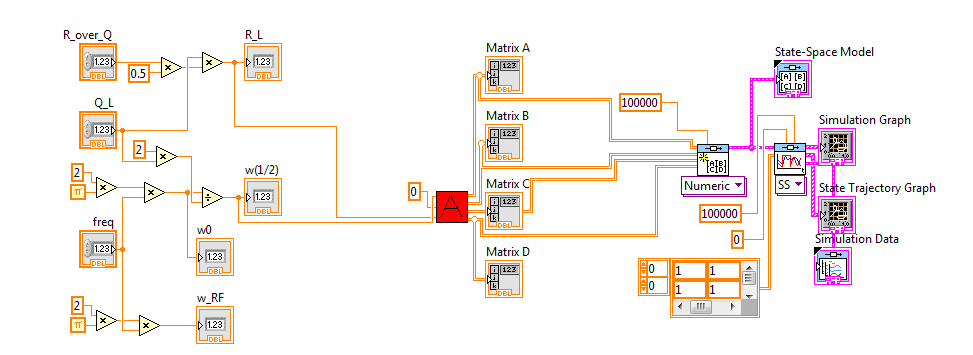
The problem is that you are assuming that LabVIEW runs left to right. Stream does not work that way. Your code like this:
does not say LabVIEW He must run everything from left to right. What happens is that it runs to the 3 'island' of the code in parallel and, in this case, it will be "empty" values You must remove the local variables to do this job and paradigm of data flow runs your code from left to right, as you wish. Here is the code:
Also, one last thing. Your contribution to the Simulation of the 'linear' CD is equal to zero all the. This means that you try to input zero linear system, which will give you a result zero in the answer. You probably don't want that since zero as input gives you more information. If you want to see how system will reset after initial conditions, you must use 'CD Initial Response. " Or you need to change the input to the system signal. Please study this shipping example to understand how to use the linear Simulation and initial response:
C:\Program Files (x 86) \National Instruments\LabVIEW 2012\examples\Control and Simulation\Control Design\Time Analysis\CDEx time domain analysis
I hope this helps...
-
Hello;
I'm a grad student and I got my presentation tomorrow and really I need your comments.
I select a topic which is the ANALYSIS of the STATE-SPACE.
The attached file has my file vi.
I have dwsign a simple survey. control loop of l which has a transfer works then I him I convert it to a SS I do analysis.
Appreciate your quick response.
also try to clean your face a bit. use the tab containers or make it to where the person doesn't have to scroll down to view your items.
and use the suggestions of Altenbach.
-
Hello!
I'm doing a project and I'm stuck and I am in need for some help.
I made a State-space model that I use for this project. I used Matlab (with and without simulink) to simulate this model and to trace its behavior. But when I want to do this in LabVIEW, I'm stuck.
I don't want to use Mathscript, because, while it would in Matlab.
Does anyone have any ideas of how I can simulate and draw my state space model in the parameters of the matrix that I?
________________
Look at the setting, I want to draw x.
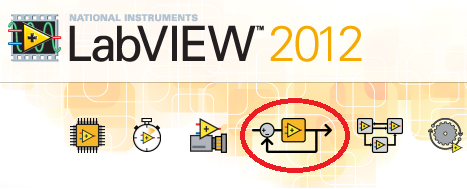
Well, you can check if you have by looking meny help > about LabVIEW... You should see this icon if you have the CD & SIM module (of course, the logo must be 2009 in your case):
Again, if you haven't and you're academic, try to talk to your administrator and check its availability. If you are a student, the student version of LabVIEW also have this software.
Doesn't depend on any other software other than LabVIEW MathScript RT Module (not the "Matlab Script node") and it allows to compile m-code directly in LV in general, its speed depends on the type of code you have.
CD & SIM module can be considerably fast, but again, it depends on what kind of code you are using. The function of the State space in control and the Simulation loop has good performance compared to the linear Simulation.vi CD.
-
Is there a limitation in state space series?
Hello
I'm developing a simulation model using the Toolbox of design control, but one have a problem with the connection of the State space models.I modeled a 11 subsystems in state-space and as soon as I have them with cd_series (ss and ss) two by two. When the berries of the vector exceed the size of 50 x 70, I received the message:
Memory is full
the highest level 'namevi.vi' VI was arrested to unknown on the NI_linSys_LinSys Conversion.lvlib:CD block diagram convert TF for .vi SS (LinSys)I modeled the same subsystems creating the transfer instead of the State space function and everything worked fine.
I have it has also modeled in matlab and I have no problem with the connection of models.
If I look in the Task Manager, the LabView increase memory allocated with 500 MB cons with matlab which allocates only 100 MB.There an o idea if it's a limitation of control design package or where I'm wrong?
Thank you for any suggestions.
I'm waiting for your answers.
Hi Aldo,.
I looked in the Subvi IndModelConnection.vi and the problem is not there. The series VI crashes when trying to turn the State of the space in the transfer function model.
In any case, it was step intermeeded of my model United Nations. What I can't find in the module of control system is arbitrary interconnection models.
Is it possible that this model of Miss the VI, who built the global model of a given block diagram models of dynamic systems interconnection?
Can you tell me if there are any VI or screws that can make this feature in this module?
I look forward to your reply.
Laurentiu arnould
-
The amplitude of the frequency. Bode CD. State space
Hi all
Gently, I have a simple model that gives me a Bode phase and magnitude, using the block 'CD Bode'. AFAIK, this block takes the representation of the State space and assesses the frequency and scale of the system.
Can I change the value of the Phase or amplitude Bode? by means change the input signal that bode uses to evaluate the response of the State space?
Note: The entry, I want to say here is the value of the sinusoidal signal that Bode uses to give the phase and the amplitude of the State space.
Thank you
The works of Bode CD functions as a "sweep" of all frequencies and who you are. The algorithm is not a frequency controlled, he comes back the entire spectrum. You can't just get a specific frequency. However, if you use the fuction 'Assess frequency of CD', you can provide the model and frequency, and this will give you the specific Mag/Phase for this frequency. This example shows how to do this in LabVIEW:
C:\Program Files (x 86) \National Instruments\LabVIEW 2014\examples\Control and Simulation\Control Design\Time Analysis\CDEx Lin Simulation and stable State.vi
Now, if you want to 'form' your frequency, so you can create another model, connect with each other and try to change the output frequency. This example shows how to do this:
C:\Program Files (x 86) \National Instruments\LabVIEW 2014\examples\Control and Simulation\Control Design\Frequency Analysis\CDEx frequency analysis
If you just want to "simulate" the response of the signal to a specific sine wave, then you will need to you another function in the time domain palette called "linear Simulation CD. With this, you can generate a specific sine wave and you can see his behavior in the time domain. Here is an example:
C:\Program Files (x 86) \National Instruments\LabVIEW 2014\examples\Control and Simulation\Control Design\Time Analysis\CDEx sine wave with Mathscript.vi
Hope this helps,
-
Representation of State-space Discrete in FPGA
Hi all
My goal is to simulate a State-space model is the FPGA cRIO (order to use an observer).
I am currently trying the simulate on my computer without using the VI state space discrete Control Design and Simulation Toolbox (since there is no model of State-space for the FPGA VI). However my representation of the discrete state-space model does not work.
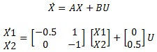
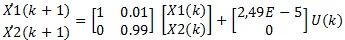
It is under a continuous state space model:
Then I got the model discretized (using the zero-order-hold and t = 0.01 s):
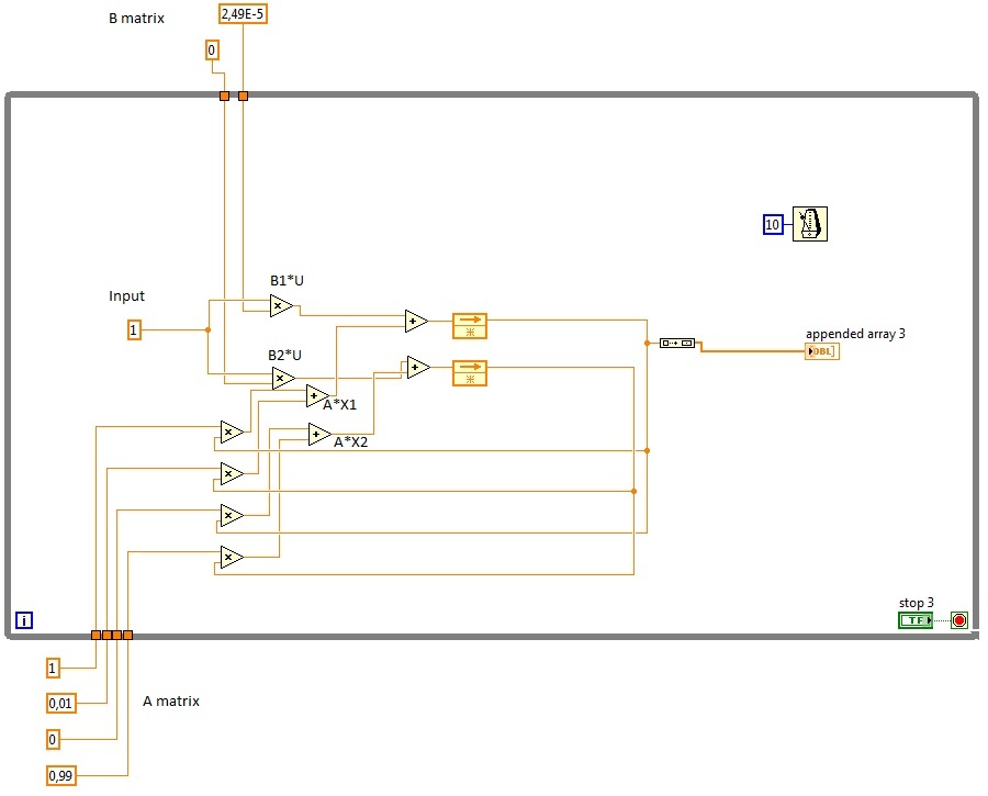
Here are the State-space discretized model I designed (to develop a similar model in the FPGA):
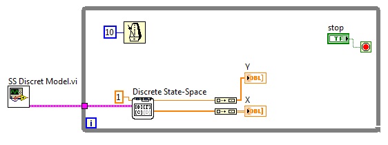
This is the VI space of discrete states that I use to compare the results:
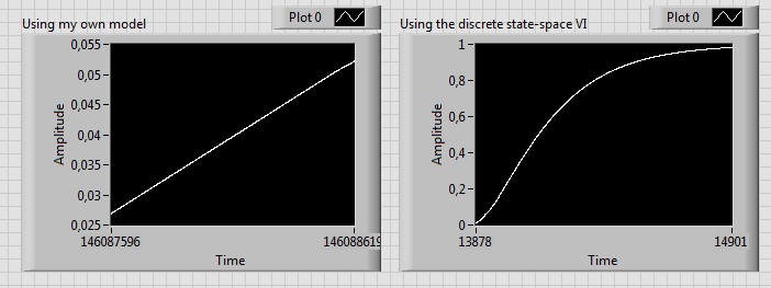
The chart plot the State X 1, which is growing indefinitely. However, it should look like a first order, as you can see:
I don't understand why the State X 1 progresses like this, I know I'm missing something (saturation of integration?).
Thanks in advance
Kind regards!
PS: Does anyone know if application other than the PID controller is feasible in the FPGA cRIO? I also have to wonder about the inversion of the matrix if I want to use the Kalman gain in my observer.
PS2: I apologize for my disorganized/not clear Labview files, I start with him.
Hello
I think that the problem can be caused by errors in your matrices A and B of rounding. Have you tried to make her show values more accurately?
MATLAB calculates these values as: A = [0.995, 0.009925; 0 0.99], B = [2.488e - 5; 0.004975]
Kind regards
Ian
-
Hello
I'm trying to control the timing of a timed loop. So far, I have tried several approaches via the software and which worked very well except the time loop in some missed cases 1-2 Ms I want to make sure the timing is right. I tried to provide an external clock through the acquisition of data I. The system I use is NI USB-6212. It has two counters and DIO and AIO, but I keep getting errors. I tried two different approaches. One was to use directly the game 'DAQmx create calendar Source.vi' in frequency mode, and when I did, I got error 200077. Then I found a post of somone saying that sometimes it is not possible and an alternative method is to use the same vi but set task of loop control mode. This one gave me Error200452. For this one you will see in my attachment the suggestion was to use an AI then the moment of him and then use this task for Creat DAQmx synchronization Source.
I don't know what the problem is or if I need to put something differently.
Please let me know if you can help me with this.
I'll try to continue to work on that, but if anyone of you a suggestion I'll be very happy to consider the issue.
Thank you in advance,
Best, Massimo.
Massimo,
In my view, the errors that you see are the result of your hardware USB-6212 is supporting the functionality of the task control loop. I have a M Series PCI card that is capable of operating both of your screws attached without problem (although they still +/-1ms variation on occaision). When I try to use a USB-6212 simulation, I get the same error codes that you do. Unfortunately, it's just a case of a lack of equipment.
Kind regards
-
Hello
is there an effective way to control loop externally?
If I try to control a while loop and my stop button is outside the loop it does not work.
If I use the local variable inside the while loop, it works, but the execution of the loop is not fluid.
is there a good way to control the loop from the outside?
You can send an event of many different loops. You need to register in each loop. Once understand you how to use events, they are a very useful tool. There are examples here in the forum. If you need help to find let them us know and someone will help you find the refrerences.
-
How to properly temporarily disable all channels except one in the multichannel PID control loop?
Hi all
Help me please to solve the problem. How to correctly temporarily disable/enable all channels except one in the multichannel PID control loop?
Thanks in advance,
Oleg
Hi Oleg,
the entry "Car?" of the AdvancedPID is a table – as well as MS and pv entries.
So what's the problem say - / allowing for a control (aka of entry) instead of all loop?
-
Primary control loop and loop DIO
Hello
I use an X-series with Veristand 2011 card. I need to acquire some AI and DI whole. It seems that the AI will be supported by the main loop, which is very good for our goal for now. But what of the DI. Looks like the DIO loop works like a rate of decimation of the main loop. So here are the questions:
- How can I set the decimation rate so that I control the rate of EID?
- Can I put the decimation at 1, so both primary DIO loop have the same speed of iteration and can probably be defined in phase?
THX.
L
Hello
You can control the OID in VS 2010-> System Explorer-> target->
-> target-> DAQ decimation digital lines. In my system of VS 2010, '1' is the default value for the DAQ decimation.
See you soon,.
-
on the timing and the GUI control loop
Hi all
I have a code with two buttons placed on the Panel, one is EXECUTED, another is STOP. Initially, STOP is disabled and when I launch RUN, the JUDGMENT will turn off. But when the JUDGMENT is made, the RACE will be activated.
#include "testimg.h" #include
#include #include "asynctmr.h" #include #include #include #include #include "toolbox.h" static int panelHandle = 0; static int stoprun = 0; int main (int argc, char *argv[]) { int error = 0; nullChk (InitCVIRTE (0, argv, 0)); errChk (panelHandle = LoadPanel (0, "testimg.uir", PANEL)); SetCtrlAttribute(PANEL, PANEL_STOPBUTTON, ATTR_DIMMED, TRUE); errChk (DisplayPanel (panelHandle)); errChk (RunUserInterface ()); Error: if (panelHandle > 0) DiscardPanel (panelHandle); return 0; } int CVICALLBACK MainPanelResponse(int panel, int event, void *callbackData, int eventData1, int eventData2) { if (event == EVENT_CLOSE) QuitUserInterface (0); return 0; } int CVICALLBACK RunButtonResponse (int panel, int control, int event, void *callbackData, int eventData1, int eventData2) { if (event==EVENT_COMMIT) { int N=20; stoprun = 0; SetCtrlAttribute(panel, PANEL_STOPBUTTON, ATTR_DIMMED, FALSE); SetCtrlAttribute(panel, PANEL_RUNBUTTON, ATTR_DIMMED, TRUE); for (int i=0; i My code is a repeat for N times, once the START button is kicked. And if the STOP button is started until the task has finished running. Stop the current application and returns the value false. I wrote the code, but it seems does not work. It seems that the application cannot be interrupted before the file for the task. I don't know what's wrong with my code. If you have any experienence with this, could you please tell me what is the problem with my cdoe? Thank you.
What you see is the expected behavior: in your loop inside the run key, you have a 5 second wait in which the system is frozen, then another 2 sec with the system frozen again. For the simulation need, you must change the code this way:
double tini;

tini = Timer ();requestToStop = 0;
while (Timer () - tini < 5.0 || requestToStop) {
  ProcessSystemEvents ();
  sleep (50);
}
The stop button then must trigger a global variable that stops the loop (requestToStop in my example above).
In actual code, such a long-term process should not be handled within a control reminder: you will need to place it elsewhere depending on how you want to structure your code in order to let the user interface responsive. Available alternatives are:
-A reminder of timer UI
-A reminder asynchronous timer (similar to the preceding but executed in a separate thread)
-A separate thread issued with CmtScheduleThreadPoolFunction
If this date is the solution, the stop button must be manipulated inside the code by triggering a signal enabling the treatment stop securely.
-
standard with a state machine controls
Hello
I read with VISA to a serial device. I am writing for the series the start character and the device sends data.
Now after reading the data, I want to stop sending in writing to the series a stop character. Separate loop is playing.
I want to do a stop button that written in the series and a start button that writes serial and bed data. Is it possible to do without a state machine?
BTW, are there examples for a series of reading and writing of State machine?
This has proved to be a bit more complicated as I first thought. If I wrote you a demo. Just add your series writing and reading the code when indicated.
It is not a state machine. It looks more like a producer-consumer architecture. Product event loop start and stop commands. The other loop is executed according to the orders. The trick was to get the series reading loop so that it could be stopped at any time and restarted at any time.
-
State machine, controls, and indicators
Hey everybody,
I'm working on the conversion of a VI to use a state machine architecture. In other words, there are several buttons that trigger States through a structure of the event in the standby mode. Two States need write values in the same set of indicators, but the rest should be left alone. Several States also contain a Subvi, which takes a cluster entry. The cluster is composed of about 10 digital/boolean controls. I wonder what is the best way to deal with these two problems. I could use local variables or references, but that seems to be discouraged for most cases. I do not have access to the VI himself at the present time, but it might send more later if necessary.
You could go with the local population, in this case it should be ok, or have an update-state indicator.
I have probably to take the easy road and go with local to a simple state machine.
/Y
-
Engine using a state machine control logic
Hello
I'm trying to implement motor control using the logic of the state machine. My requirement is simple. I have a voltage from data acquisition value that corresponds to the couple (initial value = 5). I need my feeding motor a positive (right-hand rotation) and negative (counterclockwise rotation) speed depending on whether the value of this tension is between the top (7 V) and the lower thresholds (3 V).
In other words, the motor starts to turn in a clockwise direction at the outset; the voltage is declining, as soon as we get to <= 3="" v,="" it="" changes="" direction="" and="" moves="" counterclockwise="" till="" it="" hits="">= 7 V, then changes direction again and this repeatedly for, say user-defined number of cycles. I tried to write this logic, and when I run the program it starts well, is to see the first time, entry happens under a low threshold, changes direction but oscillates at the same position. He won't until > = 7 V.
I enclose the code for your reference. Logical machine state in queue can be of any help? Also, can I present a State in which after that user-defined cycles are more the engine back to a position where the voltage is 5 V.
Thank you very much.
Ravens fan is OK. You need to know which direction you are moving before deciding what to do comparison. Look at this simple diagram that shows how to use a shift register to keep track of which direct that you use.

Maybe you are looking for
-
Re: Can Satellite L30-106 - I switch the RAM to 2 GB?
HelloI want to upgrade the Ram in my Toshiba L30-106 running Vista. The vehicle currently has 2 * 512 MB modules. In the specifications it says it can handle maximum 2 GB of Ram. Is this correct? Can I upgrade using 1 * 2 GB or 2 * 1 GB modules? Dual
-
Print screen while using dual display on Tecra M5 monitors
I have a Tecra M5 in a docking station, and I use the laptop as a primary monitor screen and an external LCD display as the secondary. Whenever I use the function Print Screen, I find that it copies both screens to the Clipboard. Is there a setting o
-
Equium P200-1ED - have a problem with the installation of driver VGA
Hello I have problem with installing driver vga video, every time in installion on that he stops Version: 6,14.10,4833 and it has error poping up... Help, please!
-
[Z70] Error starting LibStartStub.dll
I had the Lenovo Z70 located a short while and everytime I turn on the machine, I get the error message - RunDLL - there was a problem starting C:\Program Files\Lenovo\Communications Utility\LibStartStub.dll How can I get rid of this? Comment to Mode
-
X1C gen2 wan 4g in the United Kingdom
I have a 2gen x1c. I want to install an em7355 or em7345. This work of the 4g uk frequency cards? I use EE. Thank you