Draw a model of State-space
Hello!
I'm doing a project and I'm stuck and I am in need for some help.
I made a State-space model that I use for this project. I used Matlab (with and without simulink) to simulate this model and to trace its behavior. But when I want to do this in LabVIEW, I'm stuck.
I don't want to use Mathscript, because, while it would in Matlab.
Does anyone have any ideas of how I can simulate and draw my state space model in the parameters of the matrix that I?
________________
Look at the setting, I want to draw x.
Well, you can check if you have by looking meny help > about LabVIEW... You should see this icon if you have the CD & SIM module (of course, the logo must be 2009 in your case):
Again, if you haven't and you're academic, try to talk to your administrator and check its availability. If you are a student, the student version of LabVIEW also have this software.
Doesn't depend on any other software other than LabVIEW MathScript RT Module (not the "Matlab Script node") and it allows to compile m-code directly in LV in general, its speed depends on the type of code you have.
CD & SIM module can be considerably fast, but again, it depends on what kind of code you are using. The function of the State space in control and the Simulation loop has good performance compared to the linear Simulation.vi CD.
Tags: NI Software
Similar Questions
-
Representation of State-space Discrete in FPGA
Hi all
My goal is to simulate a State-space model is the FPGA cRIO (order to use an observer).
I am currently trying the simulate on my computer without using the VI state space discrete Control Design and Simulation Toolbox (since there is no model of State-space for the FPGA VI). However my representation of the discrete state-space model does not work.
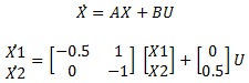
It is under a continuous state space model:
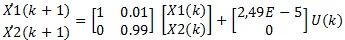
Then I got the model discretized (using the zero-order-hold and t = 0.01 s):
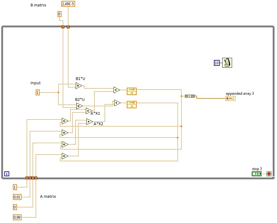
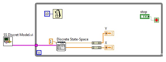
Here are the State-space discretized model I designed (to develop a similar model in the FPGA):
This is the VI space of discrete states that I use to compare the results:
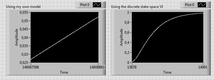
The chart plot the State X 1, which is growing indefinitely. However, it should look like a first order, as you can see:
I don't understand why the State X 1 progresses like this, I know I'm missing something (saturation of integration?).
Thanks in advance
Kind regards!
PS: Does anyone know if application other than the PID controller is feasible in the FPGA cRIO? I also have to wonder about the inversion of the matrix if I want to use the Kalman gain in my observer.
PS2: I apologize for my disorganized/not clear Labview files, I start with him.
Hello
I think that the problem can be caused by errors in your matrices A and B of rounding. Have you tried to make her show values more accurately?
MATLAB calculates these values as: A = [0.995, 0.009925; 0 0.99], B = [2.488e - 5; 0.004975]
Kind regards
Ian
-
Is there a limitation in state space series?
Hello
I'm developing a simulation model using the Toolbox of design control, but one have a problem with the connection of the State space models.I modeled a 11 subsystems in state-space and as soon as I have them with cd_series (ss and ss) two by two. When the berries of the vector exceed the size of 50 x 70, I received the message:
Memory is full
the highest level 'namevi.vi' VI was arrested to unknown on the NI_linSys_LinSys Conversion.lvlib:CD block diagram convert TF for .vi SS (LinSys)I modeled the same subsystems creating the transfer instead of the State space function and everything worked fine.
I have it has also modeled in matlab and I have no problem with the connection of models.
If I look in the Task Manager, the LabView increase memory allocated with 500 MB cons with matlab which allocates only 100 MB.There an o idea if it's a limitation of control design package or where I'm wrong?
Thank you for any suggestions.
I'm waiting for your answers.
Hi Aldo,.
I looked in the Subvi IndModelConnection.vi and the problem is not there. The series VI crashes when trying to turn the State of the space in the transfer function model.
In any case, it was step intermeeded of my model United Nations. What I can't find in the module of control system is arbitrary interconnection models.
Is it possible that this model of Miss the VI, who built the global model of a given block diagram models of dynamic systems interconnection?
Can you tell me if there are any VI or screws that can make this feature in this module?
I look forward to your reply.
Laurentiu arnould
-
The amplitude of the frequency. Bode CD. State space
Hi all
Gently, I have a simple model that gives me a Bode phase and magnitude, using the block 'CD Bode'. AFAIK, this block takes the representation of the State space and assesses the frequency and scale of the system.
Can I change the value of the Phase or amplitude Bode? by means change the input signal that bode uses to evaluate the response of the State space?
Note: The entry, I want to say here is the value of the sinusoidal signal that Bode uses to give the phase and the amplitude of the State space.
Thank you
The works of Bode CD functions as a "sweep" of all frequencies and who you are. The algorithm is not a frequency controlled, he comes back the entire spectrum. You can't just get a specific frequency. However, if you use the fuction 'Assess frequency of CD', you can provide the model and frequency, and this will give you the specific Mag/Phase for this frequency. This example shows how to do this in LabVIEW:
C:\Program Files (x 86) \National Instruments\LabVIEW 2014\examples\Control and Simulation\Control Design\Time Analysis\CDEx Lin Simulation and stable State.vi
Now, if you want to 'form' your frequency, so you can create another model, connect with each other and try to change the output frequency. This example shows how to do this:
C:\Program Files (x 86) \National Instruments\LabVIEW 2014\examples\Control and Simulation\Control Design\Frequency Analysis\CDEx frequency analysis
If you just want to "simulate" the response of the signal to a specific sine wave, then you will need to you another function in the time domain palette called "linear Simulation CD. With this, you can generate a specific sine wave and you can see his behavior in the time domain. Here is an example:
C:\Program Files (x 86) \National Instruments\LabVIEW 2014\examples\Control and Simulation\Control Design\Time Analysis\CDEx sine wave with Mathscript.vi
Hope this helps,
-
Closing state space control loop
Hello
I am a student MYSELF and has been assigned to a project closing a loop of a rotary inverted pendulum control.
I have all the mathematical equations and state space design.
I don't have any idea on how to apply the system in closed loop state space in Labview (10)
any suggestion where start/examples?
Thank you very much
Gil,
Hello Gil,.
A great way to implement and simulate your SS system is to use the Module LabVIEW Control Design and Simulation.
Here is a short list of references on modeling in LabVIEW
Basics of Control Design and Simulation in LabVIEW
http://zone.NI.com/DevZone/CDA/tut/p/ID/10685Tutorials for LabVIEW controls
http://zone.NI.com/DevZone/CDA/tut/p/ID/6368
Once you have installed module, it is an example of navigation in LabVIEW on the inverted pendulum.
I hope this helps!
-
Hello;
I'm a grad student and I got my presentation tomorrow and really I need your comments.
I select a topic which is the ANALYSIS of the STATE-SPACE.
The attached file has my file vi.
I have dwsign a simple survey. control loop of l which has a transfer works then I him I convert it to a SS I do analysis.
Appreciate your quick response.
also try to clean your face a bit. use the tab containers or make it to where the person doesn't have to scroll down to view your items.
and use the suggestions of Altenbach.
-
(Control design and Simulation) State-space block don't gives result
I tried and tried but failed to get the State-Space block module to give me a graph / output.
I have no idea what the problem is and I hope someone can help me. Numbers and calculations work in Matlab (Simulink) but I can't simulate in labview.
Anyone have any ideas?
The problem is that you are assuming that LabVIEW runs left to right. Stream does not work that way. Your code like this:
does not say LabVIEW He must run everything from left to right. What happens is that it runs to the 3 'island' of the code in parallel and, in this case, it will be "empty" values You must remove the local variables to do this job and paradigm of data flow runs your code from left to right, as you wish. Here is the code:
Also, one last thing. Your contribution to the Simulation of the 'linear' CD is equal to zero all the. This means that you try to input zero linear system, which will give you a result zero in the answer. You probably don't want that since zero as input gives you more information. If you want to see how system will reset after initial conditions, you must use 'CD Initial Response. " Or you need to change the input to the system signal. Please study this shipping example to understand how to use the linear Simulation and initial response:
C:\Program Files (x 86) \National Instruments\LabVIEW 2012\examples\Control and Simulation\Control Design\Time Analysis\CDEx time domain analysis
I hope this helps...
-
Draw supports models, as an illustrator of office?
I'm debating buying an iPad Pro and it would be useful to know how easy it is or it is difficult to import an image into the Draw and place it as a 'model' to 50% or 40%. I think there are solutions for this, but part of 'model' of the application of draw draw?
Hi Birck,
I want to just make sure that I understand how you use the word 'model '... Do you want to just be able to import an image into a photo layer and to rely on it?
Scroll down in this tutorial to add an Image to the track and let me know if that's what you want to be able to do: https://helpx.adobe.com/mobile-apps/how-to/illustrator-draw-get-started.html?set=mobile-ap ps - basics - adobe-illustrator-draw
Sue.
-
Hello
Can someone tell me if some provision of thin disk space is possible in templates using Lab Manager?
The context in which this question:
-We have 2 t byte organization areas
-Say a model is a starter of XP SP3, Vista, Windows 7 SP1, 2008 R2 OS with very little on it but set to say have a 30G hard drive
-Lets say the need for OS boot's say 4G
Ideally, we want our models to consume 4G disk and when a clone of link is used, the clone starts to use additional disk space.
= > Is this possible?
Don't we have to live with the consumption of 30G model? So if the area is important to us, can we do the following (I know that it works under ESX)
-in the example, create a 5G model
-After link cloning, extend the disk space to 30G, and then inside the BONE, expand drive C: to 30G?
I'm new to Lab Manager and trying to get an idea of its internals on ESX or local workstations.
Thank you
UH... it's already out there: http://vmware.com/download/labmanager
-
Flex 4: model component: STATES: Null problem
Hello
I have created a model based on the following link component
http://help.Adobe.com/en_US/Flex/using/WS2db454920e96a9e51e63e3d11c0bf69084-79c3.html
My component uses STATES, and my code assign a new runtime component in daze. When I run the code, I get "cannot access a property or a method of a null object reference." Error.
Help, please
Code in the main file
     <local:TemplateComp>
          <local:Edit>
               <s:RichEditableText/>
          </local:Edit>
     </local:TemplateComp>
Model component Code
<?xml version="1.0" encoding="utf-8"?>
<s:VGroup xmlns:fx="http://ns.adobe.com/mxml/2009"
           xmlns:s="library://ns.adobe.com/flex/spark"
           xmlns:mx="library://ns.adobe.com/flex/mx"
           verticalAlign="middle" horizontalAlign="center"
           width="400" height="300" initialize="vgroup1_initializeHandler(event)">

     <s:states>
          <s:State name="State1"/>
          <s:State name="SECOND"/>
     </s:states>

     <fx:Script>
          <![CDATA[
               import mx.core.UIComponent;
               import mx.events.FlexEvent;
               public var Edit:UIComponent;

               protected function vgroup1_initializeHandler(event:FlexEvent):void
               {
                    BaseArea.addElement(Edit);
               }

          ]]>
     </fx:Script>

     <s:Label text="First View" includeIn="State1"/>
     <s:VGroup id="BaseArea" includeIn="SECOND" width="200" height="200"/>
</s:VGroup>
Hello
When you use the component States are word instantiated until they are displayed if you add the 'immediate' components = itemCreationPolicy property, you must reference until the status is shown he will solve your reference error
David
-
Hello
I understand the States of accomplishment we need to report during the execution of the order, in this process, I created the external execution States that I am expecting to receive the external system of accomplishment in each type of control function component specification CRM system. After that, I created the map to set the Mapped state that I need to report to the CRM and rules of Composition level command and element of realization.
But actually I have several questions about job States:
-Where can I see the status of external and State mapped in the point of Data\Order of control Structure and where can I see the status of the order resulting from the command Composition Ruleset?
-How can I change the external executing State during execution of the function? I need to put in place an automated task to run an update of the order in the process of HRT or something is automatic?
-How should I send the State map to CRM? Can I use an event or an automated task in the process for this purpose, or is there an automatic way to do?
Thank you in advance.
Concerning
AndresGHi AndresG,
You use O2A cartridges or not?
If you do not, by default, the States of execution are at the location - next
(a) status of external-/ ControlData/functions//orderItem/ExternalFulfillmentState
(b) status of composite (i.e. the output of composition FS)-/ ControlData/OrderItem/OrderItemFulfillmentState for items and/ControlData/OrderFulfillmentState order for the blanket order.
Note that mapped fulfillment States are not preserved.These default values are configurable by creating the FulfillmentStateModule.xquery file and the catalog XML to include the file. In fact, this is how O2A cartridges replace these default values; the States of execution are stored in the /OrderLifeCycleManagement. area
Yes, you can update the status of external achievement during execution of the function - in your automation function, simply send back the external executing State in your xquery automator.
You need to send State composite realization to CRM, Yes, create an event Notification has changed data - configured to trigger by change of the State of Composite implementation.
See you soon,.
Daniel Ho
OSM product management -
How to reference the substitution model in State of PL/SQL string
Hello - I need display conditionally an article based on the value of #TITLE #. I'm trying a function body pl/sql expression returning a Boolean
DECLARE
PAGE_TYPE VARCHAR2 (1000);
BEGIN
PAGE_TYPE: = lower (substr (:TITLE,instr(:TITLE,'Query')));
If (page_type = "query") then
Return TRUE;
on the other
return FALSE;.
end if;
END;
There are no errors, but the condition is not met, whereas it should be.
I tried to adjust some elements of the application to the value of #TITLE # and I'm obviously not reference properly. they are all null:
: Test_value: = & TITLE. ;
: TEST_VALUE2: =: TITLE;
: TEST_VALUE3: = V ('TITLE');
Help?
Thank you
CarolHello
Your can use the page title attribute in the metadata as...
SELECT page_title
INTO my_var
FROM apex_application_pages
WHERE application_id = :APP_ID
AND   page_id = :APP_PAGE_ID
???
See you soon
Ben
-
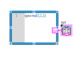
While solving a problem of the State space, I used the MathScript node to enter a code. Next, I added some inputs and one output for the node. but I'm not able to change the type of the output 'Model SS'. His does not work. (I'm not able to select this opyion.)
Then, just try to do the following script:
sys = rss (3,1,1);
and do the "sys" as your output on the node. It should give you the State space model.
Note that my model is a model of "state-space". If your model is another type, such as a transfer function, you will need to convert the art model using:
sys = ss (sysTF);
-
Beginner: Conversion of signals in response
Hello, I'm new on this and could not find sufficient support inside LabView or other messages here.
Since I got it, it's that I need step response Control Design VI.
It appears to require State-Space model it seems that I have to convert my signals oscilloscope in matrices.
This does not however, and I'm afraid that I might not even have the right approach. What should I do to make it work correctly?
Thanks for the help!
Attachment: Photo of block diagram
Chris
Your connection is meaningless. The "Create State-Space" requires you to give the 'model' format 'State Space '. The Signal from your acquisition is not that. If you are really looking to convert a generic signal in a model, you must use the "System Identification Toolkit', which should be available under 'Treatment of Signal' or 'Control and Simulation' palette if you have installed. Here, you will need to use the 'SI estimate transfer function Model' or 'model to estimate State - Space SO"to get the model, use the" IF convert to CDT models "to convert the model with noise deterministc model used by Control Design and the 'step CD response' to calculate the step response of the model. Who should provide the information says that you are looking for.
Now notice that if you are able to control the excitement of your system, then you could simply generate a 'step' in input signal and measure the strength of the signal and looking at the answer, then you should be able to get the response of the system directly...
hope this helps
-
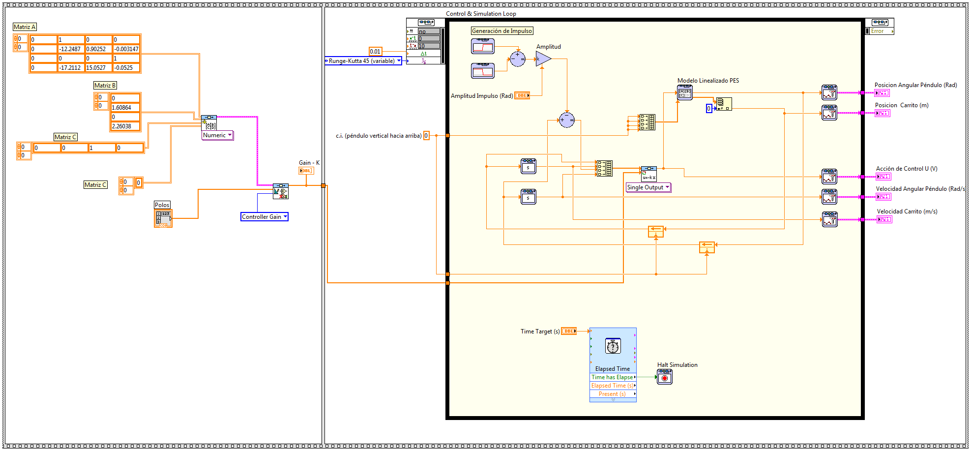
I wonder if there is someone who could give me a helping hand with a simulation, that I'm running. I am trying to simulate the behavior of a system modeled as state space and do a controller using different techniques, but I'm having problems and can't advance too far... It seems that the simulation loop gets on a sort of infinite loop and he can't stop but I don't know what else to do... Left, I enclose the block diagram of one of the screws simulation I so could someone there watching.
It is a model of an inverted pendulum system and a cart modeled as state space and try to see the behavior of a placement of pole due to a pulse controller imput. Initially, I would check a model no length I have but it was too weird so I replaced it with the linear model to the point of unstable equilibrium, but the VI stuck too then I felt motivated to post here.
(I tried to join the extract by using the code below, image generatin capture tool so you can download and run the code, but it's my first time using this tool, so hopefully it will work well... I created the extract .png and gasket here using insert image... that is right? )
In the Simulation node, shift registers could have different behavior which would explain the problem that you run in. So, if you want to 'break' the feedback node (which in general, you shouldn't need to do), then use the block of 'memory '. He'll try to behave as you would expect.
In addition, you can look at the example of shipment for the linear simulation:
C:\Program Files (x 86) \National Instruments\LabVIEW 2014\examples\Control and Simulation\Case Studies\Mechatronics\Inverted Pendulum\Linear inverted pendulum Simulation.vi
Or non-linear simulation:
C:\Program Files (x 86) \National Instruments\LabVIEW 2014\examples\Control and Simulation\Case Studies\Mechatronics\Cart-Pole\CDEx Cart-pole control and Simulation.vi
as a reference for your example. You notice even reuse the animation for your application.
Maybe you are looking for
-
Satellite A210 PSAEGE - need to control the driver XP for bus
Hi all I am a user of a Toshiba Satellite A210 PSAEGE and changed operating system to Windows XP.The problem is that I'm missing a driver control of the bus (the CPU is AMD Turion 64 x 2). I searched in the Toshiba and AMD web site and did not find t
-
Satellite A210 - card Wireless-N upgrade project
I want to upgrade the Wireless card in my A210 a G a N. What is the card compatible? Although management will, I installed an Intel 5100, the wireless card does not work. Something to do with the switching circuit. The laptop will not 'see' the map!
-
I bought this laptop a few months, put it away in a corner and when is it coming out my old laptop broke. I got it at low cost, was handed to nine Windows 8 PC, I've updated to 8.1 in early December. I use this laptop heavily, I watch a lot of videos
-
I'm unable to access my Windows Live Mail. No matter what I do, I always come with a message box that indicates that she "performs a task" of sending two e-mails. There is no error reported. I can't get beyond this area.
-
Mount the 3 tops and a background exponential
I m quite new on labview. My version is 8.6 I have a spectrum with: 3 peaks (I want to go with 3 Gaussians) exponential background How can I install? Thank you