Coded frequencies-16 generator control switch
I feel really lame to ask this, but I can't understand how to connect a code switch to select 16 different frequencies in the generator module. I keep trying to figure out how with a switch output and a generator of output that I can control the generator of the switch. I can't imagine how the goes - inta and outta goes to get wired.
I keep thinking, I saw one such example, but can't find it
CJ, the example was everything I needed to make things work properly. It was logical that the output voltage of the coded switch would control the signal generator which he does very well.
Thank you very much!!!
Tags: NI Products
Similar Questions
-
In order to control the number of cells in a column chart, I need a control switch that can choose between the numbers for example. 2048, 1024, 64, 128 and 256, 512. Is there a switch of LabView or vi for this action?
Emmanuel says:
Jeff· Þ· Bohrer says:
APOK, this is exactly why we use controls to ring like that of my last post
 there is no need for all these tables of choice.
I did just 'rube d' new?

No, as you will get Rube had, just go to school. Forum participation is often a source of learning for all of us. Keep wallahs what you know!
-
Control switch radio wireless (Fn + F5) via the Windows registry / software
In a school environment, students have discovered that they can cause problems using the software switch Fn + F5 to turn off the Wifi radio. I know that the material LED turns off when this happens, but the teachers are too busy to identify it. The result is that users are unable to connect, and the Windows Welcome screen is not quite intuitive, which gives a message error "there currently no server connection.
I am interested in applying a "fix" to this problem at startup. Maybe a fix Windows registry to "force" the Lenovo software switch to turn on the Wifi.
I had a bag autour with a comparison of registry Interstate market and am currently getting the following (among other changes, such as DHCP etc.) diff:
HKLM\SYSTEM\ControlSet001\Control\Class\ {4D36E972-E325-11CE-BFC1-08002BE10318} \0018\RadioEnable: 0x00000000
HKLM\SYSTEM\ControlSet001\Control\Class\ {4D36E972-E325-11CE-BFC1-08002BE10318} \0018\RadioEnable: 0x00000001
HKLM\SYSTEM\CurrentControlSet\Control\Class\ {4D36E972-E325-11CE-BFC1-08002BE10318} \0018\RadioEnable: 0x00000000
HKLM\SYSTEM\CurrentControlSet\Control\Class\ {4D36E972-E325-11CE-BFC1-08002BE10318} \0018\RadioEnable: 0x00000001However, forcing these dwords to 0 x 1 doesn't seem to be enough to turn on the radio.
Has anyone else had a similar experience? Is there a BIOS/UEFI underlying setting that might be able to be accessed via the software?
Acxtually that I found after searching a bit more. Can be controlled via the command line:
"C:\Program Files\Lenovo\HOTKEY\TpFnF5.exe" /wlon
-
Dynamics control switch in dash prompt (or invite all switching)
Hello
I would like to know if it is possible to dynamically change the control to a column in a command prompt. I will allow users to switch between "Drop-down", "Edit box" and "multiple Sélection" control for a specific column in a command prompt.
Is it possible, maybe with javascript?
Another solution for my problem would be 3 different guests (each different control of a witch for column) and make visible or hidden. But how to hide or show the based on the choice of the user...
Thanks for some tipsNo direct approach, try this...
Create a prompt that displays the options drop down menu, Multiselect, Editbox
SELECT case when 1 = 0 then tableA.col1 to another 'dropdown' end 'domain '.
Union SELECT case when 1 = 0 then tableA.col1 to another "Multiselect' the end 'domain '.
Union SELECT case when 1 = 0 then tableA.col1 to another "Editbox" end OF "domain".Set presentation variable: pval
Now, create three guests...
Create three reports
Report1 - add a column-> in the fx-> case column where 1 = 0 then end on the other 'drop-down list' tableA.Col1
Add a filter on the column is equal to presentation variable pvalI2 - add a column-> in the column fx-> box when 1 = 0 then "Multiselect" else tableA.Col1 end
Add a filter on the column is equal to presentation variable pvalReport3 - add a column-> in the fx-> case column where 1 = 0 then end on the other 'Editbox' tableA.Col1
Add a filter on the column is equal to presentation variable pvalDashboard change Goto
Add five sections
Section 1 - Add prompt choice - Dropdown, Multiselect, Editbox
Section 2 - Add the prompt1
Section 3 - Add the orders2
Section 4 - Add the prompt3Section 5 - Add the three reports in there and hide the section.
To hide the section Goto-> Section-> properties-> custom-> use custom css css styling option-> enter the code below
{display: none}Section 2 Add guided navigation-> to which mean Report1, defined to describe the return lines.
Similarly do for the other section invite...Thank you
Vino -
Switching between the 2 sets of values controlling the axis y in a xy chart.
All, morning
I am very new to this (like 2 days now) and will soon sit the Labview core 1 and fundamental measure, bare with me!
I'm basically extraction 2 string values that is issued by a Board of Directors, I have by IP, one value for line voltage and the second measure concerns the battery voltage.
I would like the option to use a control switch to differentiate between what is entered the chart at the push of a button.
Is there a way to do this?
Thank you very much
Alex

Have you tried the Choose function?
-
Step by step with NI 9503 motor control: cycle of use can be 50%
Hello world
I am using the module NOR 9503 with a cRIO 9006 to control an engine step by step using this module to rotatate a number of measures (480 steps) can change the direction of rotation. The frequency of the signals phase should be 200 Hz. What I need is a simple open-loop drive. No need to torque smoothing, anti-resonance coefficients, angle of correction... etc.
I tried using the example project in Labview "NOR 9503 Stepper point Position Drive". I changed so that I could set the market factor for each phase as a parameter (to 50%). Please find attached my project.
The question is when I run it, generated signals have the duty of less than 50% of the cycle. You can find oscilloscope capture in the folder "Capture". I don't know what the problem is. Please help me. Thank you very much.
I have the Labview 2014 and SoftMotion toolkit.
Best regards
Hi Paul,.
Thak you for your help.
My need is to drive an engine with 200 Hz frequency. Generate an output signal that will have this frequency playing on its cyclical report? The idea is to generate a 2 kHz PWM signal and run of 99% for a half of the period (2.5ms at 200 Hz) and then change the operating factor to 0% for the second half of the period. and so on. I think that in this way we have a resulting signal of 200 Hz.
But the challenge is to know how to generated 4 output signals? and how to change the direction of rotation?
Best regards
Lahcen
---------------------------------
-
Hello
in 10g R2, where another other Alertlog check the frequency of the control point?
In alertlog I have:
Thread 1 cannot allot of new newspapers, sequence 3064
Checkpoint is not complete
I don't see why. Any idea?
Thank you.
I tried this:
ALTER SYSTEM SET fast_start_mttr_target = 20 SCOPE = BOTH;
But in the alertlog I saw:
Sun 15 Nov 09:55:54 2009
ALTER SYSTEM SET fast_start_mttr_target = 20 SCOPE = BOTH;
Sun 15 Nov 09:56:10 2009
20 FAST_START_MTTR_TARGET is outside the valid range of MTTR, use 461.
Sun 15 Nov 09:57:31 2009You can see the frequency of log switch again to check the frequency of control because each log switch causes a checkpoint. Your control point has not completed because can be order of paper happens faster. Run the following query.
SELECT *.
V $ loghist
ORDER BY first_time DESC;Concerning
Asif Kabir -
Blue contours appeared and I can't control my iphone 5 s. I can't go to settings. I triple click on the button "home" and gives a message to go into settings and enter the password but I can't get to the settings. What does not work? Thank you
The blue plan is switch control.
s http://gettecla.com/blogs/News/15538916-what-is-switch-control-mode-in-apples-IO
Triple click to get rid of him.
"Siri to the rescue. I said turn off the control switch. »
Re: How to disable the switch control
I don't get a request for an access code. What is a school system?
switch control
Settings > general > accessibility > switching control
R
-
DAQ USB 6363 - generate digital data series through the single DIO line
Hello
I'm new with Labview, currently, I bought NI DAQ USB 6363 for generating control signals and signals analog accquire. I would like to send digital data series through one of the digital IOs with throughput of 30 kbps. Please see the attachment for the data frame. Could someone comment the feasibility of this? Y at - it codes for the example that I can refer to? Most of the examples I've looked at so far deals to generate several line instead of 1 single line. How can I achieve this?
Thank you
Diem
Hey diem.
After looking on your code, I understand what you were trying to do. Here's how I'd do. Usually we do not write code to clients, but you peaked my curiosity of! I hope this helps. Good luck!
~ kgarrett
-
using 6341 USB frequency generation device but level is droped when conect
I use the DAQ USB-6341 material for frequency generation. The desired frequency is generated correctly but when I connect to any other device, the voltage level, I mean that the peak to peak of the frequency voltage has dropped to 0.6, 1 Volt and also the frequency has varied. I unplug the charge or unit frequency becomes constant and peak-to-peak voltage becomes 5.
Please some help me solve my problem.
Thank you
Best regards
Naseeb
-
Hi all
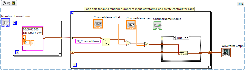
I thought of a great way to make automatic adjustments on a random number of data types in a table 1 d:
So I have a loop for that to lets say a table 1 d of waveforms as input. I want to be able to adjust the gain, offset, and enable/disable waveforms them individually, with their respective witnesses on the front panel.
The name of each control should take the name of the waveform, with the extension of functionality for example. gain, offset, and activate.
So if the waveforms are called Data1 in Data10, then the code should generate controls called "offset Data1',"Data1 gain", 'Data1 enable'... throughout the Data10...
Each order must be placed in a control pane in front and with a property node, they are arranged in a nice way (at least that's my current thought).
I hope that makes sense, what I'm trying to do, and some of you are able to give me an idea of how begin! I tried to sketch it in the following...
Best,
Tommy
One idea would be to make a table from a cluster of controls, and then use a property node to display as many controls have you waveforms.
Chris
Then an array of Clusters is a good idea, I'm not sure how you get unique names (like 1 Chan, Chan 2, etc.). But groups of sense. Create a cluster with Gain and Offset Enable and make a TypeDef out of it. Now this on your face where you want channel 1 to be. Label of the cluster of channel 1 - LabVIEW natural "grouping" of the pole 'control' will do the rest and more properly (in my opinion) than to have a channel 1 Gain, channel 1 Offset, select channel 1. Of course, this works only if you can group the controls in a nice way (note that LabVIEW allows you to easily organize items in the cluster either horizontally or vertically, and once they are aligned, you can turn off the alignment and 'solve' positioning). Best of all, if tweak you the TypeDef, then any 'Control Channel' put you on your face will look the same.
Bob Schor
-
Several switches inside the a test sequence
Hi all
I'm doing a few stages of switching in a single Multiple digital limit test, so what I did is incorporated all the controls switch in labview. Unfortunately, I got an error when he got to the step with the switching (an error occurred when trying to access device PXI1Slot6
Another process has already logged to this switch module.).Is it possible to disconnect the teststand switch so that the labview vi can be used without interruption, or y at - it another way to do switching multimode in teststand I don't know?
Thank you for taking the time to read.
One more thing...
You can use the adapter of the sequence with a step of the multi-digital. Then create a sequence that will have several stages.
I illustrate this in the sequence file attached.
Let me know if you have any questions.
-
Game K430 with Turbo, auto, Cool switch machine.
How will I know if this switch is working properly?
rmose
Windows 2008
1 TB HARD DRIVE
12 GB memory
Hi rmose,
The software is called power control switch and it is a propriertary for Lenovo K430 software. There are no links available for download again on the thelenovo support site yet, but as far as I KNOW, if you're running in Ultra Mode (red light), the system is already working in Ultra circles and you won't need the power control switch.
Kind regards
neokenchi
-
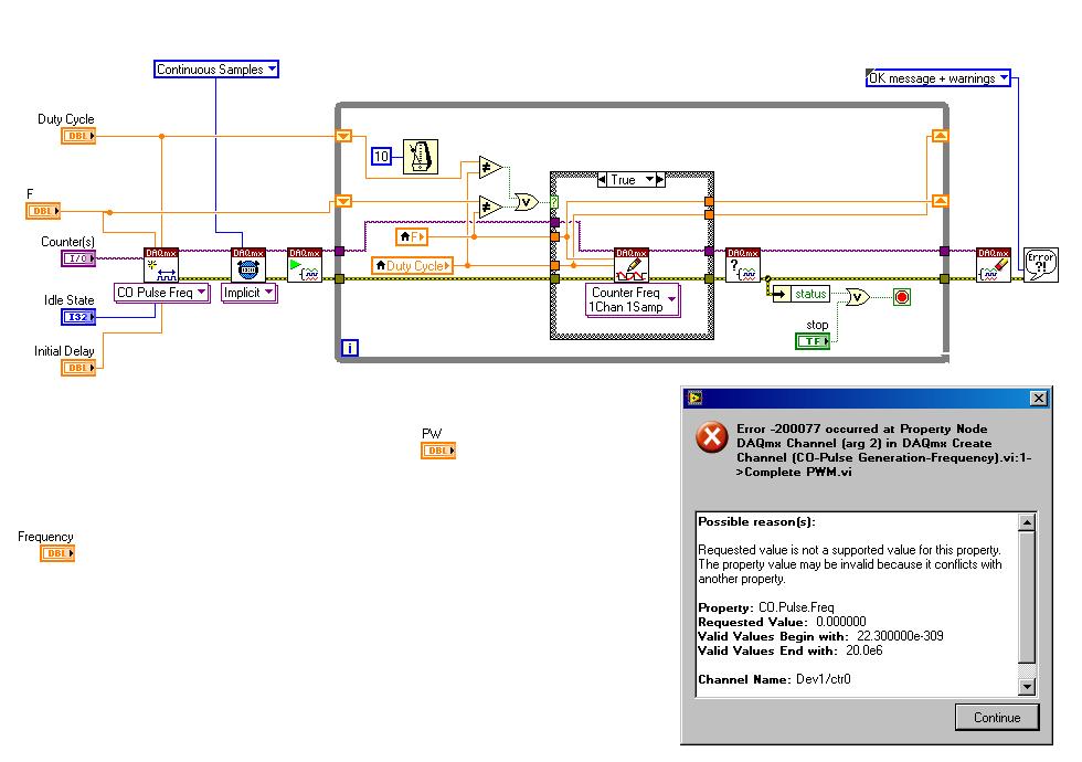
If I replace the control with another why DAQmx create channel once complain a false claim?
I tried to replace the frequency by another control in the example found here complete PWM:
http://www.NI.com/white-paper/2991/en
However, I get the following error message:

Possible reasons:
Requested value is not supported for this property value. The value of the property may be invalid because it is in conflict with another property.
Property: CO. Pulse.Freq
Required value: 0.000000
Valid values begin with: 22.300000e - 309
Valid values ending with: 20.0e6Channel name: Dev1/ctr0
Task name: _unnamedTask<10>
My wiring diagram looks like this:
If I cancel my change (i.e. I have remove the frequency control knob and turn it over to the control of the example, it works perfectly.) I get the waveform is displayed in the oscilloscope.
My goal is to simply use a frequency and duty cycle control knob. How can I achieve this?
There are two things to do.
What I think you did now changes the scale of the handle.
You will also need to change the values that are allowed to enter. You will do on the data entry tab in the dialog button properti.
Uncheck the 'use default', the Minimum value limits and Maximum identical to your balance.
Value "Response to value out of range" Coerce to both Minimum and Maximum.
I hope this helps.
Let me know if you have more problems. -
Hello everyone,
I am puzzled about the problem I've encountered in my vi. It's acquisition of forces from a load cell and he recorded the coordinates of the point of my motion system.
I added a block to trigger, which sends the TTL 5V signal to a PIV system, trigger works, and I can read signal meter and PIV starts its sequence after him. What I am tryint to accomplish is to start recording to the file and trigger at the same time.
I tried to bulean my "writing on a file" control switch wire to digital bool > slot, but when I run vi, as soon as I press "record", labview freezes. If I create a bulean dedicated control for relaxation (which is what I have in attached file), everything works fine.
Can someone proposes a possible solution?
Thanks in advance
Oleks
Update,
I found the problem. Apparently, I have to pay attention to the error message. The cause for the program of 'freeze' was my attempts to write data in a switched to the broad external hard drive... Ouch
It's working now.
Oleks
Maybe you are looking for
-
Satellite A200: No audio after update SP1 and NET Framework
Hello After my laptop Satellite A200 update Microsoft .NET Framework 3.5 Service Pack 1 and the .NET Framework 3.5 Family Update (KB951847) x 86 andInternet Explorer 8 for Windows Vista, the speakers and the headphones stopped working. When you go to
-
Satellite M40x-134: my cell phone tracking stolen
My Satellite M40x-134 with serial # 65241250K was stolen from my car yesterday. How can I track through centers of Toshiba or any other method?
-
Exchange system user passwords
When the computer is powered, the first user is able to log in with their password. After that, the computer changes the user passwords. the next user must turn off the computer and back upward in order to connect with the password. What happens a
-
keep folders being created for each jpg file
For these last days, an additional file for each hard disk jpg file is automatically generated that contains always two new jpg files (vcm_s_kf_m160_106x160.jpg and vcm_s_kf_repr_320x480.jpg). How can I stop it and if possible cancel it?
-
No noise in the Windows Vista machine.
Victorinox original title: have no sound. I have no sound on everything that I try to run