Compact fieldpoint helps!
Hi, im currently using compact fieldpoint cFP-2120 with modules cFP-AIO-610 (X 3) cFP-TC-120, cFP-RLY-425, cFP-DIO-550. The question I have is im using cFP-AIO-610 to measure the voltage. The question that I saw that I can for example measure 3 Volts on channel 1, then I connect on channel 2 (not during the connection to channel 1). And it will not read 3 volts it gives less than a tenth of this value and the current increases value if I try to increase the voltage. Ive checked my connections on the connector of the CFP, MAX and everything seems ok. Is the broken module? It could be filled? Ive even changed the module to another and same problem. What it could be?
Stu
This issue is currently addressed through technical Support UK.
Tags: NI Hardware
Similar Questions
-
LabView is in real-time for Compact FieldPoint necessary?
Hello!
LabView is in real-time for Compact FieldPoint (CFP) necessary?
(in German: Ist für die von Compact FieldPoint LabView time use real necessary?)
Thank you.
Bye, Ouafa
Hello
If you just want to use Labview for logging and graphics (via Ethernet) AND that you do NOT use a CFP-real-time controller, you don't need to LabVIEW Real-time.
For example if you use OR cFP-1804-Ethernet/Serial Interface for Compact FieldPoint.
(http://sine.ni.com/nips/cds/view/p/lang/en/nid/202527)
If you are using a controller real time you WILL LabVIEW Real-time.
You can't function without it!
Best regards
Mencef
-
How do I program labview to read all 8 compact fieldpoint modules?
I am new to fieldpoint and I my set-up block diagram to read 8 strain gauges using a SG-140 module. My basket is filled with strain gauge modules 8 SG-140, and I need to know how to fix my diagram to read all 8 modules of SG - 140. So, I need a total of 64 strain gauge readings 8 modules of SG - 140. Can I do this without really copying what I've already done 8 times more? Is it possible to use a loop or something to read the 7 other modules? I appreciate any help I can get.
My opinion about not having to duplicate the table of index based on what your VI was showing at the time. Once you have the VI implemented with multiple modules, then you will need to implement an array of unique Index stretched far enough to get all the channels of interest. From a 2D array, you need to connect both the row index and column index for a single scalar element. So first channel would be 0 and 1, then 0 and 4, canal next 0 and 7. The next module would be 1 and 1, 1 and 4, 1 and 7.
-
Why can't read Compact Fieldpoint more tension?
Hi, im using PSC 2120 with 3 cfp-aio-610. For some reason any, it is
Impossible to read more than one my circuit voltage to 2 separate
points (See Diagram). If I try to join several analog input, I have
Download high-voltage current smaller. Ive had the help of NEITHER, but they
not been able to solve my problem. Starting to think I should have
slept with my recorder data of Agilent as this Works Fine.Stu
stu22,
The user for the AIO-610 manual says pins 18 & 20 (common) on the AIO - 610 are tied together internally in the module. Looking your circuit diagram, which would actually be a short circuit, the "charge" and pour a large amount of current through your shunt. Post some info on your overall application and maybe we can find a solution.
-
Well, this answer is a bit dated, but I finally bought a PSC 2200 and am able to download and run all the screws fit without problem. I thought I should post an update for those who follow me.
Thanks for the help.
-
Hello!
I have both Outlook 2003 and Outlook Express 2003 loaded on my computer
Only, I use Outlook Express and have not used regularly Outlook in 5 years.
I have no problems using Express, (both in the sending or receiving of emails).
There is no "snap-emails" sent or received in Outlook regular and none in the Outbox. The same with the Express.
About every month, compresses files Outlook Express and in doing so, the folder sent items do not get compressed, it does not create a new file SentItems.bak and it gives me the error: has SENT the file is currently being used by Outlook or by another application.
All the time this problem started, I received a number of updates to Office 2003 from Microsoft (probably updates 20-25). They have installed without incident and that's the only problem resulting, I had with one of the components of Office.
Thanks again for your help. I'm looking forward to this problem so that it works correctly.
John MurphyThe sent items folder may have a corruption. Create a new folder and copy the text in the folder into the new folder. Then close OE and delete the file sent items.dbx. OE will create a new. DBX files should not receive more than a few hundred megabytes or they get corrupted.
A more effective solution: since you seem to have corruption, it may mean that there are more, if you can set up a new message store by clicking file | Identities. Then you can add your accounts, use the file | Import | Messages to bring them from the old identity. Which will remove all corruption.
Whatever it is, it's a good time to save your messages in OE, because it tends to remove them in unexpected ways. See www.oehelp.com/OETips.aspx#6 also, if resumes default Outlook, he likes to do when he starts to date, just see www.oehelp.com/oedef.aspx
See if that helps.
Steve
-
web control problem compact fieldpoint
Hello
I have a vi wrote to the PSC 2110. It reads the values of a set of uf PSC-HAVE-110 of the blocks of analog input and writes the values to a cfp-do-401. The program has two periods loops, to read and save the values to 6 hz and another to control three exits on the DO-401 to move a cylinder back and forth for a few tests of life cycle.
When I run the program for the development on the PC it works fine, stops at the end of the cycle I set, etc. When I build and set it to run when you start and connect to the PSC 2210 with a web browser, it also works very well and stops as it should as one remain in 'control' of it on the web browser. However, when I start it up, then release control and just monitor, it will not stop as it should. The user interface controls indicate that the ITO judgment, but the cycling continues to go and it keeps count. Whenever I do a control of the application in the browser, it stops as it should.
What is the difference between "control" and monitoring with regard to the delivery of the program? I intend to leave this race without supervision and I really need to stop in time.
Thanks for any info that could relate to this.
Thank you
What I did to solve this problem, is to create local variables of the controls I had to exploit by program and write to them. Rather than use the node property Value. It works fine now.
-
8,6 of fieldpoint installation problem
Hey everybody,
I installed a laptop to Labview 8.6 real-time with 8.6. For some reason any he doesn't let me install Labview 8.6 real-time on our device compact fieldpoint. I reinstalled, twice. Still, when I go to add/remove programs and you try to install the latest version, he mentions the RealTime 8.5.1 as the highest upgrade available on the host. Even when I try to do a custom Setup, it still lists 8.5.1 as the most recent update. When I go to the my computer > software it tab lists in time real 8.6 as installed.
We have an important to test and I need help fast.
That is right. The 20xx family is not supported for LabVIEW Real-time 8.6.
Kind regards
Stephen S.
-
module of compact field not found in max point
I have a CFP-2120 and 8 rear slot plan. Module what ever, I put in the 8 slot THAT MAX can't find it. I swapped back them plans and 2120 controllers, but the problem remains. I add the device in MAX and try to configure it manually I get the message "the device is in offline mode" for this add-on. The lights on the module that I put in the slot 8 are in green.
MAX 4.6 version
LV 8.6
Field point 6.02
I suspect I'm missing something simple, but I can't.
Thank you
Take a look at this article.
-
Error in firmware PSC 2020 & Max connection time-out error
Hello!
My PCP 202O status LED will blink twice - which indicates that there is an error in the firmware (according to the user manual). I have already installed the latest firmware downloaded from the Web site of NOR and it says that I'm supposed to update the operating system of the remote system in MAX. When you try to update the system BIOS, it happens.
Version on the target distance: 10.1
Available on the host version: 10.4
I'm a little confused as to which is the remote target and that is the system that hosts? He also says that the previously installed software will be removed if editing continues and it could damage the material so started or off so I'm a bit skeptical to proceed manually.
I have error alsoreceiving messages in maximum errors in MAX are 'connected - no software installed' and connection to a remote device has expired. I wonder if this error occurs due to the firmware issue, or is it because of the timeout settings? What is the best? A period more or less?
I'm new with this. Any info is greatly appreciated! Thank you!!!
The target is your compact Fieldpoint. The host is your PC that you are. Given that the PC has a newer version, you will want to have the software downloaded to the CFP by MAX. Of course, there is a small chance that you could lose power to the PCP if your luck is bad and that the power is off in the middle of the upgrade. It would be better to have your diet for the CFP running off a battery backup UPS for safety.
I'm guessing that the error is due to your firmware issue.
If you are really unsure on how to proceed, it may be best if you contact DIRECTLY, they can help guide you through the update process.
-
buffer allocation and minimizing memory allocation
Hello
I am tryint to minimize the buffer allocation and memory in general activity. The code will run 'headless' on a cRIO and our experience and that of the industry as a whole is to ellliminate or minimize any action of distribution and the dynamic memory deallocation.
In our case we treat unfortunately many string manipulations, thus eliminating all the alloc/dealloc memmory is significant (impossible?).
Which leaves me with the strategy of "minimize".
I did some investigation and VI of profiling and play with the structure "on the spot" to see if I can help things.
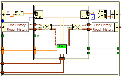
For example, I have a few places where I me transpoe a few 2D charts. . If I use the tool 'See the buffer allocations' attaced screenshot would indicate that I am not not to use the structure of the preliminary examination International, both for the operation of transposition of the table for the item index operations? As seems counter intuitive to me, I have a few basic missunderstanding either with the "show stamp" tool of the preliminary examination International, or both... The tool shows what a buffer is allocated in the IPE and will once again out of the International preliminary examination, and the 2D table converts has an allowance in and out, even within the IPE causing twice as many allowances as do not use REI.
As for indexing, using REI seems to result in 1.5 times more allowances (not to mention the fact that I have to wire the index numbers individually vs let LabVIEW auto-index of 0 on the no - IPE version).
The example illustrates string conversions (not good from the point of view mem alloc/dealloc because LabVIEW does not determine easily the length of the 'picture' of the chain), but I have other articles of the code who do a lot of the same type of stuff, but keeping digital throughout.
I would be grateful if someone could help me understand why REI seems to increase rather than decrease memory activity.
(PS > the 2D array is used in the 'incoming' orientation by the rest of the code, so build in data table to avoid the conversion does not seem useful either.)
QFang wrote:
-My reasoning (even if it was wrong) was to indicate to the compiler that "I do not have an extra copy of these tables, I'll just subscribe to certain values..." Because a fork in a thread is a fairly simple way to increase the chances of duplications of data, I thought that the function index REI, by nature to eliminate the need to split or fork, the wire of the array (there an in and an exit), I would avoid duplication of work or have a better chance to avoid duplication of work.
It is important to realize that buffer allocations do occur at the level of the nodes, not on the wires. Although it may seem to turn a thread makes a copy of the data, this is not the case. As the fork will result in incrementing a reference count. LabVIEW is copy-on-write - no copy made memory until the data is changed in fact, and even in this case, the copy is performed only if we need to keep the original. If you fork a table to several functions of Board index, there is always only one copy of the table. In addition, the LabVIEW compiler tries to plan operations to avoid copies, so if several branches read from a wire, but only it changes, the compiler tries to schedule the change operation to run after all the readings are made.
QFang wrote:
After looking at several more cases (as I write this post), I can't find any operation using a table that I do in my code that reduces blackheads by including a preliminary International examination... As such, I must STILL understand IPE properly, because my conclusion at the present time, is that haver you 'never' in them for use. Replace a subset of a table? no need to use them (in my code). The indexing of the elements? No problem. .
A preliminary International examination is useful to replace a subset of the table when you're operating on a subset of the original array. You remove the items that you want, make some calculations and then put back them in the same place in the table. If the new table subset comes from somewhere other than the original array, then the POI does not help. If the sides of entry and exit of International preliminary examination log between them, so there no advantage in PEI.
I am attaching a picture of code I wrote recently that uses the IPEs with buffer allocations indicated. You can see that there is only one game of allowances of buffer after the Split 1 table D. I could have worked around this but the way I wrote it seemed easier and the berries are small and is not time-critical code so there is no need of any optimization. These tables is always the same size, it should be able to reuse the same allowance with each iteration of the VI, rather than allocate new arrays.
Another important point: pads can be reused. You might see a dot of distribution on a shift register, but that the shift register must be assigned only once, during the first call to the VI. Every following call to the VI reuses this very spot. Sometimes you do not see an allocation of buffer even if it happens effectively. Resizing a table might require copying the whole table to a new larger location, and even if LabVIEW must allocate more memory for it, you won't always a point of buffer allocation. I think it's because it is technically reassign an existing table instead of allocating a new, but it's always puzzled me a bit. On the subject of the paintings, there are also moments where you see a point to buffer allocation, but all that is allocated is a 'subfield' - a pointer to a specific part of an existing table, not a new copy of the data. For example 1 reverse D table can create a sub-table that points towards the end of the original with a 'stride' array-1, which means that it allows to browse the transom. Same thing with the subset of the table. You can see these subtables turning on context-sensitive help and by placing the cursor on a wire wearing one, as shown in this image.
Unfortunately, it isn't that you can do on the string allocations. Fortunately, I never saw that as a problem, and I've had systems to operate continuously for months who used ropes on limited hardware (Compact FieldPoint controllers) for two recordings on the disk and TCP communication. I recommend you move the string outside critical areas and separate loop operations. For example, I put my TCP communication in a separate loop that also analyses the incoming strings in specific data, which are then sent by the queue (or RT-FIFO) to urgent loops so that these loops only address data of fixed size. Same idea with logging - make all string conversions and way of handling in a separate loop.
-
implementation of generator electric automation in labview
I'm a grad student. I am doing my final project on automation of generator.
my project is->
I want to view, input voltage (mains voltage), temperature, fuel level, current load. If the supply voltage is interrupted, it automatically goes to the other power to start the generator. Now he's going to keep the generator temperature detection. If it exceeds 50 degrees celcius then generator will be automatically stopped. If the fuel level is below certain level, then it will sound the alarm. At the same time, I want to display the fuel level and temperature on the LCD.
It comes to my project.
I want to ask can I implement this project using the FPGA and LABVIEW?
What devices I have to buy for this (FPGA board)?
about, what will be the cost of Board and sensor devices?
Help, please. I'll be very grateful to you.
I agree with Smootastic, but NEITHER will not be able to provide everything you need to make all these measures. You talk about a wide range of sensors for all these tasks. You will need of thermocouples and RTD/themistors for measurements of temperature (see www.omega.com or www.marlinmfg.com), you will need a level indicator (Omega, Newark, Allied Electronics, etc.) and ammeter with alarm output (Grainger? McMaster Carr?). You have a catalog to search for.
I don't know FPGA is needed to do this, have you considered Compact Fieldpoint? Your rep OR can advise you better.
-
Performance issues on large applications of RT NSV
Hello
The end of http://www.ni.com/white-paper/12176/en says "...". misuse of shared Variables in LabVIEW Real-time application may cause performance poor machine... Bad typical uses include the use of too many shared Variables... In deployed applications to small targets in real-time such as RIO Compact or Compact FieldPoint, not more than 25 variables should be used. »
That apply to the alias of e/s network-published as well? I intended to have 100 ~ i/o alias (cRIO-9082 + 2 x OR-9144), exposed to a Windows PC for DSC logging/alarming - or would that be a problem?)
Hi JKSH,
Using the cRIO 9082, you should be allowed to accommodate a large number of IO alias. According to the controller, you can run into problems where there are limitations of memory on the controller. However, this controller must have more than enough memory to support that a large number of variables. The best way to get an idea of how variables affect your system is to monitor the CPU usage and the memory of MAX. I also recommend to install just the necessary software on the cRIO and not everything is possible. I hope this helps and if you have any other questions please let me know.
-
Blocking communications ethernet CFP-2200
I support a system time real DSC LabVIEW and Compact FieldPoint (PSC-2200 and I/O).
After repeated connectivity issues:-recording of data stops and cannot be restarted from HMI
-Can ping the CFP very well
-MAX sees the CFP, system status indicates "connected - Running.
-Navigating around Max, sometimes get the pop up "cannot communicate with the FieldPoint network module.
-When you try the keyMAX, responds with "Unable to send commands to the remote system." Then the State of the system changes into "Disconnected" (but can still can ping the PSC ok). Requires restart of the cFP-2200 (RESET button on the front)
What should I check?
Related issue:
If the communications network between the HMI server and the CFP is interrupted momentarily, communications usually heal without intervention?
It is an isolated network (only the server and the PSC on the link), but there are a pair of MOXA deveices between both wireless bridge.Thank you!
-
LabVIEW: 8.2
Material: cFP-2120 (Compact Fieldpoint)
I have a collection of embedded data VI who collects a row of data once every 5 seconds. At the start of the VI it synchronizes time with a time server the Fieldpoint NIST. Up to this point, he was on the spot with the hour UTC.
Recently, data has introduced the gaps in some areas and the frequency of sampling of twice the rate expected. When I looked at the data that I discovered some segments of data were offbeat time so that they overlap with other data files. The strange thing is that it was only some segments and not systematically biased.
Here is a screenshot of the timestamp, generate the script.
What could be the cause of the problem?
Jeremy
I think I may have found the problem, but I do not know why it happens. There are two screws datalogging running at the same time and independently of each other. Each VI stores data in its own text file. Once a file reaches 10 MB in size of VI synchronizes time with NIST and creates a new file.
For some reason, whenever a VI cycles and synchronizes with NIST, the other VI timestamp is compensated by a day. Why would this be the case?
I changed the screws so that they synchronize only with NIST at the start of the VI and not every time a new file is created. If the error should come once again going to be another day or two until the data files reach their limit of 10 MB.
Maybe you are looking for
-
How to change engine yahoo of google search as a default startup or default mozilla page
Yesterday, my friend was install Filezilla on my pc.Then automatically my pc loads very slowly.I check my network, then I found this site below automatically(id.search.yahoo.com/?fr=hp-ddc-bd-tab & type = bl-bfr-ob-rhb-33__alt__ddc_dsssyctab_bd_com)T
-
new iphone more 6s and cannot get my songs bought on it
I got a new iPhone 6s more yesterday. I backed up my 5 seconds old before getting the new phone if I when I got the new phone I restored from the backup point. I got my apps all downloaded, but my purchased music will not play. It shows in my musi
-
Troubleshooting information are too large
When you post a question to the Mozilla Support (here), the troubleshooting information do not provide sufficient space. The max is 30,000 characters, but my troubleshooting information is 45 102 characters. Can you please increase the length allowed
-
If the virtual machine can be harmful?
VPC may be dangerous for my pc anyway. I have average can do something wrong?
-
Good afternoon I was wondering if I can get the password bios reset for a HP Folio S13-2000. The disabled system code is: 53899087 Thank you kindly