Conditional probes
Hi all
I was hoping I might be able to get a little help with conditional LabVIEW probes in 2015. My understanding about the conditional probes, it's that I would have to option to create a conditional probe for the data type of the thread I'm probe by going to the menu "Custom probe. As in if I right click on a cluster of error thread I should be able to right click-Online Custom Probe-online conditional error probe. My problem is that no option is there when I go to "Custom Probe". I have only options for the 'Orders' and 'new '.... ». Anyone can do the light as to where I could get the parameter to include conditional probes in my menu custom default probe?
Thank you very much!
Ian
Thanks for the iniput, I worked in fact just the solution myself. If someone else falls on a problem similar to the problem with my 'LabVIEW data' folder having appeared in a place that does not exist. So LabVIEW was not load default probes in the folder _Probes on the inside, and they were not to appear. The solution was to go options and point the 'default data directory"to an existing location and repair of LabVIEW. Specifically, you need to change the data directory before repairing, or you'll end up sitting and waiting for LabVIEW to repair for nothing... maybe I did several times... Oops!
Tags: NI Software
Similar Questions
-
How to run a certain number of loops and stop
Hello
I now have a VI and I want to debug. Some time ago in a loop in my VI. I am interested in what happens after a few iterations.
I want simple step by step, but not for the few lines at the beginning.
How can I do this?
Thanks in advance.
Chuan
Use a conditional probe out of the node iteration of the while loop. You may need to run a wire from the node to the edge of the loop if you are not already using the node, then right-click the on wire and select Custom probe-> conditional I32 probe, and then select the conditions to get him to take a break.
-
Place the breakpoint by program
Hello people,
Is there no way to set the breakpoint by program or break VI on occasion?
You are probably looking for a conditional probe: right click on a thread > probe Custom >...
In Sad help for 'probes', then select 'custom of creation. "
Happy VI - ing!
-
with WSN Vernier temperature probe?
Hello everyone. I have a hard time trying to get the sensor measures.
I created the thread here: http://forums.ni.com/t5/LabVIEW/steinhart-hart-with-vernier-thermistor/m-p/2811150
I think that now the formula is fine. So I realized, it could be that I chose the wrong node to work with probe thermistor based.
So now I took node voltage/resistance NI WSN-3226. I don't know how to wire properly. EX0, AI0, and GND.
Any help would be so awesome. Thank you
Nicely,
Poor
Poor Hello,
That's right - you get a voltage scale out, not a resistance value. The manufacturer has provided additional information on the use of their probes with different here:
Vernier: Can I use BTA Vernier sensors with another of A - to-D converter?
http://www.Vernier.com/til/1952/?keyword=WRT-BTA
In addition, it seems that there are already example screws provided making this conversion voltage - to-resistance to-probe. I have found these Vernier website with terms like "ELVIS", "BTA-vehicles" and "reduced the tension.
Vernier: Why is the temperature sensor read correctly with my NI ELVIS
http://www.Vernier.com/til/2925/?keyword=BTA-ELV
NI.com: Interfacing screw for Vernier biosensors (download of example provided at the top right)
http://www.NI.com/example/31019/en/
The VI "convert thermistor rdg" provided in the zip file seems to apply Ohm's law to determine the resistance of the thermistor of the acquired power, as you have noted.
As a note - all this information was already available on the Web site with a minimum of research NOR and Vernier. It's probably a good thing to consolidate this information in a single thread/place so that future users have access to it (that's why I'm a link everything), but by doing some research on your own or contact the manufacturer directly could have you up and running last week! In addition, you must be sure that you understand your sensor and conditioning circuit before using the computer, do not understand what is happening is a good way to end up with measurement errors.
In addition, you plan on leaving the WSN node attached to a Committee of ELVIS for the acquisition?
Best regards
-
Mapping to the signals and initial Conditions in a simulink model
Hello world. I am pretty competent with old Simulation Interface Toolkit (SIT) and I am moving to Veristand. I have some basic questions that I think that know the answer, but who want to do some checks.
First of all, when you map signals, such as the output of a block check, is it possible to make them available for mapping other that mark the test points? At the bottom of this page, it is a bit ambiguous, but it seems to suggest that if I disable optimization option will appear any sudden without needing me to mark all test points. The I am referring to something specific is the following, "Certain optimizations that you activate in Simulink can make a not available in NI VeriStand signal. You can disable these options for the entire model to all the signals available to probe, but the model memory footprint increases accordingly. Alternatively, you can mark individual signals as test points in Simulink to maintain a very reduced memory footprint by keeping test-point available signals to probe. »
My second question is in what regards the "initial condition" parameters There was a problem in SIT (although National Instruments has not agree with me at the time that it was a problem), where you can map the controls to these settings, but at the moment where you have been given access to the model, the initialize function had already been called, which means that your maps were useless. I see that I can still map to these settings in Veristand, and I wonder if the same problem exists. I'm not quite to the point where I can start trying to change these but I'm hoping to avoid the days of debugging, I lost on this whole by learning to SIT.
As a follow-up on the second question, to SIT, I could find the C code (located in nidll_main.c) that was called whenever the 'play' button and add a second call to the initialize function. So let me change the initial conditions without recompiling my entire model which, in my case, would be unworkable. If this problem still someone was able to implement a similar solution?
Optimization, you can disable in Simulink (TM) I believe is called Signal storage reuse. To my knowledge you either need to use individual test on son points, or you must disable overall re-use of storage of signal for your model.
Regarding the second question, the question still exists in NI VeriStand. This is something that we are aware of what we expect to address in a future version of NI VeriStand. The workaround you describe might possibly work if you do enough digging in the C code. Currently VeriStand charge and then initializes the model at the same time, and initializing code can read the values of model parameter. If you check out this code and move to the first call to the main function of the calendar, you could allow for the adjustment of the parameters of the model before the model starts.
-
74F283 sometimes gives wrong output on digital probes
Hello
I have strange problems with the sensors showing the wrong exit. I am designing a CPU, and what is happening on a design more complex and now even on a simple.
I am running:
13.0 Multisim education Edition
Application version: 13.0.0 (13.0.632), database version: 13.0.a
Build date: Saturday, July 13, 2013, 19:42:19
I'll be sure to include a copy of my simple circuit I brought back a multipage ALU 16 bits of 74F181 and 74F182 of an Adder 4 bits using a 4-bit Adder unique with fast include, 74F283.
The installation program:
I have 9 bits go to the entries. They are made of SPDT switches, each wired to VCC and ground, selectively.
The first four "strands" or switches (Q, W, E, R keys) control A3... A0,
The second of four switches (keys A, S, D, F) control B3... B0,
The space bar control Carry-In.
I also 3 series of XOR (74F86) switching each of the inputs and outputs on a selective basis.
1 key allows to reverse the input bits A,
Press 2 to reverse the B input bits,
3 button to reverse the output bits.
The four bits of the sum and the Carry-Out bit are each thread to their own digital logic probe (PROBE_DIG_GREEN).
The problem:
Exit lights are sometimes wrong, but the way that simple I know how to reproduce the bug is as follows:
Load the file. and run the simulation.
Press Q to switch the MSB of the seized A.
Watch the lights of the probe. They're probably showing an inverted output.
Press 3 to reverse the result.
See the same lights.
Press 3 to delete (UN-invert) exit.
The output is corrected as it should have been from the beginning.
Alternatively, press space to show lights crazy and 3.
You can compare this to allowing the LSB of the input A (R key) instead of the MSB (Q key) and see how it is supposed to work.
Why does this work? I'm doing something wrong? Is this a bug with the software? Y at - it update?
Help, please!
-Richard Collins
Student in electrical and computer engineering at SUNY-IT
Hi rich,
I replaced your switch with a digital constant interactive, it is easier to see the digital input as the bipolar switch. You can find this part in the in the Group of 'Sources' on the family of "Digital Sources". Your scheme lacked a digital pattern, it most cases this affect the circuits, but from time to time, he made another, the modified file is attached.
Also attached is an Excel file with the conditions you described and the exit, I had, I don't see a problem with the logic of the circuit. Please let me know if I'm missing something.
-
Inconsistent output in project values. Possible race condition.
I have a big project and saw many. I recently made some changes to the highest VI (do not remember what the changes were however) which led to a very strange test results, from time to time. I have a VI sub entering the model number off the coast of the ASE and outputs of an enum. If the Subvi outputs 2, shall be read as a 2 to the topVI. About 20% of cases, it generates a 0. At the higher level, the output of the Subvi connects to a typedef cluster that contains the typedef enum.
I thought about it. It turns out that it wasn't a race condition. Where I placed my probes and where I put breakpoints, it looked like the data that has been taken out of the subIV and the data in the top VI did not correspond to the top. It turns out that the DUT has a firmware which sometimes returns incorrect data.
-
Error 20023... "The following conditions must be met: 0 < f_low < = f_high < = fs/2."
Hello
I was getting some prob when I wanted to filter an EMG signal. It was a 3rd order Butterworth low-pass filter. I put the at10Hz of low cut-off frequency. He showed a msg "error-20023 occurred in filter-> Filter20023.vi Possible reason (s): analysis: the following conditions must be met: 0".< f_low=""><= f_high=""><= fs/2."="" my="" original="" sample="" frequency="" was="" 51.2hz.="" i="" didn't="" find="" any="" option="" to="" change="" the="" deafult="" sample="">
Could someone help me please? VI is attached here.
Thanks in advance.
See you soon-
Taslim
Taslim. Reza says:
Thanks Norbert. Do you have any VI (for example) to create waveform data? I want to have a look at this to understand the facts.
Just go in the palette of waveform. There is a function to build a waveform. It looks like a package by name. The dt, is what distinguishes the data rate. A represents the actual data (your table) and t0 is the start time. You don't need to worry about t0 in this situation well.
-
How to start a subdiagram when he meets a specific condition
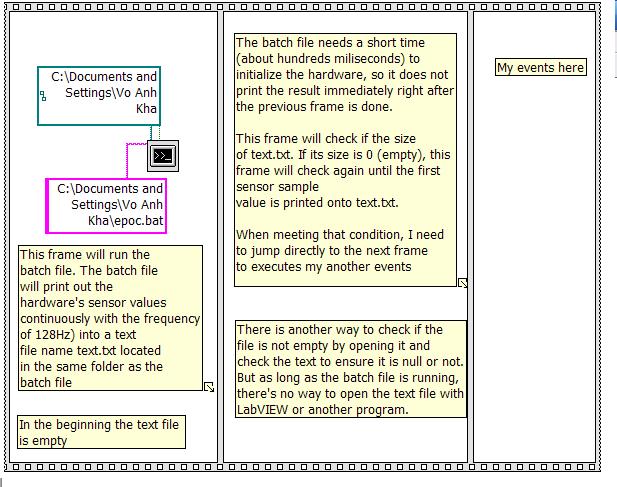
I have a file of commands (epoc.bat)
I use Labview to call this batch file. The batch file will be run a task on the windows command prompt, and it will show my value of sensor material permanently (at the frequency of 128Hz) in a text file on the disc. Please note that the batch file creates the empty text se file and then writes the values in this text file.
The problem is that the batch file needs time to initialize the material (a hundred milliseconds) before it prints the first value of the probe. My job is to determine when the first sample is printed, in order to launch my right to events after that the first value of the probe is printed.
I put my question in the VI of attached file. Also this photo below which describes clearly. I put all the events in the correct order in a sequence of dish.
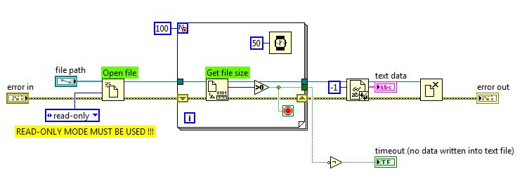
How can I determine when the first sample is printed. I think that there are 2 steps: first of all check if if the text file is available and then checking the size of the file? How can I make this work. Then and especially, how can I build a condition to run the following image?
This technique works... I just tested it...
-
I'm doing a Proof-of-Concept for the wireless, and I get the infamous 'unknown' endpoint for a device that should emerge as a Workstation Windows based on the info I received from the endpoint identity-points section. My question is if it's possible extract the information from the list of attributes of the endpoint (for example, the tcp 135 port) to use as a profile?
Here are the attributes:
Endpoint
* MAC address
* Policy assignment
Static assignment
* Ranking in an identity group
Ranking in a static group
List of attributes
135 - tcp msrpc
139 - tcp netbios-ssn
3389 - tcp ms-word-serv
445 - tcp microsoft-ds
DomaineAD truncated
AcsSessionID ise-poc/133205055/184
Airespace-Wlan-Id 10
AuthState authenticated
AuthenticationIdentityStore AD1
AuthenticationMethod MSCHAPV2
AuthorizationPolicyMatchedRule truncated
CPMSessionID 0a64001d00000005502568b6
Called-Station-ID 64-d9-89-43-09-70:NACTEST1
Calling-Station-ID 18-3d-a2-92-0a-ec
DestinationIPAddress
DestinationPort 1812
IP address of the device
Types of peripheral devices Type device Type #All #WLCs
DeviceRegistrationStatus notRegistered
EapAuthentication EAP-MSCHAPv2
EapTunnel PEAP
18-3D-A2-92-0A-EC EndPointMACAddress
Unknown EndPointMatchedProfile
Unknown EndPointPolicy
EndPointProfilerServer ise - poc
EndPointSource probe RADIUS
ExternalGroups ad.tdfadfa.org/departments/is/groups/sms-remote\,truncated
FULL CL20 domain name - isnetwrk03.ad.xxxxxx.orgg.
Framed-IP-Address
Fake IdentityAccessRestricted
Unknown IdentityGroup
Default IdentityPolicyMatchedRule
LastNmapScanTime 2012-Aug-10 16:30:41 CDT
Location location location #All #.
MACAddress 18:3D:A2:92:0 A: EC
Unknown MatchedPolicy
MessageCode 5200
Model name unknown
NAS-IP-Address truncated
NAS-identify truncated
NAS-Port 13
NAS-Port-Type Wireless - IEEE 802.11
NetworkDeviceGroups device #All Device Type Types #WLCs, location #All locations #truncated
NetworkDeviceName WLC09
NmapScanCount 2
YES Intel Corporate
PolicyVersion 4
PostureAssessmentStatus NotApplicable
RequestLatency 54
Answer {username = foo\\webb; State = ReauthSession:0a64001d00000005502568b6; Class = CACS:0a64001d00000005502568b6:-poc/133205055/184; Termination-Action = RADIUS-Request; MS-MPPE-Send-Key = 9 c: b0:32:f4:ec:35:91:8 has: 6a: fc:87:05:ba:6 has: a 4:3 c: fd:7e:3 has: bb: ff: dc:c6:cd:36:ed:14:63:3 b: 88:34:18; MS-MPPE-Recv-Key = d 16:62:80:7: 6f:1e:09:5f:24:ed:f5:5e:c5:af:7 d: fb:ef:95:c4:12:f8:55:f8:52: da: dd:b0:7 b: 9f:69:04:; }
Access to the network by default SelectedAccessService
Internal SelectedAuthenticationIdentityStores AD1, internal users, endpoints
SelectedAuthorizationProfiles PermitAccess
Type of box service
Unknown software version
Fake StaticAssignment
Fake StaticGroupAssignment
Total certainty factor 0
attribute-52 00:00:00:00
attribute-53 00:00:00:00
Cisco-av-pair audit-session-id = 0a64001d00000005502568b6
Truncated IP
operating system Microsoft Windows XP SP2 or SP3
James,
It is possible, but you have enabled dhcp probe and have you thought about establishing a statement of support ip or assign the node ISE as one of on the WLC dhcp servers?
It is built in failure that contains the dhcp class identifier MSFT will profile endpoint as a windows workstation.
However if this is not the case you can create the following condition under the policy elements > Conditions > profiling > new Profiler, you use the create (Advanced...) then select NMAP > 135 - tcp > then set the EQUAL operator to msrpc.
Pass under the Microsoft-desktop, and then select the option create a corresponding identity Group (it's much easier rather than using the option in the hierarchy) and define the certainty factor 30. Then add this new condition, then assign certainty 30 also.
Hope that helps,
Thank you
Tarik Admani
* Please note the useful messages *. -
Conditional highlighting with checkbox in the two cells by the numbers
I have two columns.
Check boxes, the other contains text.
I want to apply formatting conditional for text, based on the checkbox (true/false) value.
Hi Bebaj,
Add another column (C in this example). You can hide C when everything works.

Formula in C2 (fill down)
= IF(A2,B2,"")
A tick in a check box inserts the value of B in C, another "" (NULL)
Conditional highlighting in column B

Kind regards
Ian.
-
Unable to accept the terms and conditions of the icloud
My iPhone IS / 10.0.2 IOS does not allow me to accept to iCloud and conditions: therefore, not able to connect to the Apple ID server and cannot connect to Wi - Fi. I have already change network settings - did not help. Erase all content and settings & restored - did not help. Do not connect to a Wi - Fi network didn't happen until I applied IOS 10.02. iCloud question began the week last while on IOS 9.35 - thinking update IOS would be the solution - NOT.
Try a reset.
Try a reset.
-
Hello, I have an old macbook in bad condition, I have been editing on final cut pro (6.0.6)
If I buy a newer computer (macbook)... with a NEW version of final cut... If I transfer all my info from my hard drive to the new computer, and if this newer computer has a new version of final cut pro, it will always show my "timeline" I have... to remember all my files?
If not... If I buy the same old version of final cut (6.0.6) and any transfer to another computer, my files will appear exactly as they did when I just changed my project?
Thank you for your help, if you need more information to answer this question correctly, please ask.
JO
I asked that your post be moved to:
-
May not accept the terms and conditions, try to
Hello
IM trying to update my subscription to an application and I get an error that indicates that I must accept the new terms of Apple and Conditions but brings me to the possibility of accepting these terms and conditions as I normally get.
I restarted twice now and I'm still not able to do.
Thanks for the help.
Have you tried to sing and then again in the app store?
- Open app store
- Scroll to the bottom of the page
- Click sign out
- Click on connect
-
How to remove Code condition on iwatch after the last update
How to remove Code condition on iWatch after the last update?
Hello
On your iPhone, in the application of the watch, go to: My Watch (tab) > password - tap on disable password.


Maybe you are looking for
-
The provider's Web site will not reflect orders/quotes...We get this message"Your browser is not supported for this program.This program is expected to be launched above IE4 version! » URL of affected sites http://
-
Need advice on the Satellite M60-159
I intend to buy the laptop Satellite M60-159...What someone has it, and it of a laptop good or bad, should I go for it? I'd appreciate any comments!
-
graph XY on the TAB container does not update
Hello I have attached a simple VI, and I understand why I see this behavior: When I run the VI then the first tab is visible (where the xygraph is located), I get what I expect: I calculate the offsets, and I redraw the graph with the property node.
-
Where you turn for specific information, programming interface for devices such as webcams, etc. All MFG seems to keep the details of the Protocol between W7 and a private aircraft.It must exist somewhere. Need to write an application for a specific
-
Rename the text in a cell in the control tree during execution
Hi all In fact, I'm stuck upward at some point. On the photo front, that I have attached, there is a tree control and two buttons (re, stop) .when I press the button rename, I want the selected cell in the tree control to increase and when I get the