Configuration of 2 digital circuits in a voice GW
Hello world
I'm dealing with digital configuration 2 lines ina unique GW.
My router is a 2900, and I want to install 2 digital lines in a 2 port T1/E1 MFT VWIC2
My questions are:
What do I have to configure Dial peers for the second digital circuit to have redundancy on outgoing calls?
I've been looking for example configurations like that, but had no luck, and the documentation does not explain this type of scenario.
My logic is that I have to configure Dial peers again for the second Digital trunk, but then in configuration CUCM how can I allow users to switch automatically? I thought that in the same road group add the second line by specifying the port in "members of the Group current road", but I don't know if this is not correct, or if I should create a new routing group?
If anyone can help me it will be fully appreciated.
Yes, you need dial-peer to the two ports, depending on what you want, with the same preference, or not.
You have no control over the switching/switching of CUCM with H.323, depending on the config of the RFP.
Tags: Cisco Support
Similar Questions
-
Configuration of the digital output in the USB-6009
I have a card for the acquisition of data USB 6009. It seems that him when DAQ card is turned on, it is always default to digital output of 'High' or 'floating '. I want to default to 'low '. Is there some setting I want to 'program' the hardware DAQ to have all the outputs low when it is powered on the value? Right now I have manually enter MAX and adjust the level 'low '. Thank you very much for your help.
Sid05,
Yes, it's low of 820 ohms. Unfortunately, the way in which the system is built, it is the only choice you have without having to build external circuits such as SnowMule suggested.
AK2DM,
Thanks for pointing the USB-6000. Finally a real, if limited, the DAQ hardware. Nevermind, he was only 4 DIO lines.
Lynn
-
Want to know primary and secondary configuration to the call, Manager with the voice gateways
Hi all
Hope you all are doing well, I wanted to know that we have two other PRI service provider and we want one of them are primary and secondary schools on the other. We have two supplier dedicated 4-4 finish lines. Please provide me with the part of configuration that are required in this case and how to re a SP for primary education and another SP for secondary lines.
Thank you
Arjun keita
Hello Arjun,
For the full bridge configuration you can check the guides below, but for the PRI redundancy, you create dial-peers and specify the feedback:
https://www.Google.co.in/URL?SA=t&source=Web&RCT=j&URL=http: / / www.cisco...
Voice POTS dial-peer 1
Destination-pettern 0 t
Port 0/0/0:15
Preference 0
Dial-peer voice 2 pots
Port 0/0/1:15
Preference 1
Dest-model 0 t
Dial-peer voice 3 pots
Description incoming only
Incoming called-number. T
Direct inward dial
Aseem
(Please rate if useful)
-
How can I activate my digital Circuit VI
I'm sorry for my ignorance. I would say I have beginner to intermediate skills with LabView. However, I want to enjoy my VI of the virtual world and on a working circuit. I'm lost as to how to do it. I don't do anything complicated. It comes to my stream of VI.
Analog signal in > Amplify > fill > abnormal signal detect (a moving window of about 15 seconds) > alarm when an anomalous signal detected.
In LabView, it works very well, and now I want to do the hardware prototype. Any suggestion would be appreciated.
Nate
Hey Nate,
I suggest that you break down your circuit problem in sections, in the same way you did with your LabVIEW program.
First thing you need is an amplifier. Your local library should have tons of things. But Google is your friend. An example. http://www.hobbyprojects.com/A/audio.html
So, you want a filter. And a detector. Finally, an alarm.
You might want to try Multisim for your circuit design.
Good luck with your project!

-
Circumvention of toll - routing calls from China to voice GW United States
Hi all
I have an office in China and I'm configuring CUCM to route all U.S. calls China to voice gw office in the United States. Currently users in China face 9,001 and then registration number calls US. Users are used for numbering 9,001 for U.S. calls, so I like to keep the same numbering structure. How to configure CUCM for U.S. calls to voice gw routed to the United States in this scenario?
I'm under CUCM 7.1.3 and voice gateways are H323
Thanks to all in advance!
D.
No problem as long as the Gulf War send you the call of don't allows to route all calls as 11 digits. If the Gulf war is in place that requires composition 7 or 10 digits for calls local you must separate road of models for these area codes.
HTH,
Chris
-
Digital electronics FPGA Board Hardware Driver for Windows 10
My son just made me aware that his school has a dozen of National Instruments Digital Electronics FPGA boards, but they have never been able to get them to work or actually use them in the curriculum. It seems that he has left his instructor know that I worked with FPGA Xilinx for more than 10 years and now everyone counting on me to get these maps work. The issue seems to be the USB driver. According to the manual, I tried DEFB2012_5_2.exe which simply refused to run on this machine Win 10 x 64. DEFB_4_3.exe ran, but complained that LabView components have not been installed and that it would not continue. Could someone tell me please how to install USB driver ONLY so that we can download files of bits with IMPACT? In terms of a school budget, the investment they have in these maps is not negligible. Thank you.
Hello Dave and TGregor,
I hope I can clear some things here. I'm sorry that you run in so many questions with your boards OF FPGA.
First of all, direct responses:
The LabVIEW FPGA 2015 driver should install the components needed to use the Board with Xilinx tools on WINDOWS 7, it will not work on any system more recent that the pilot has been developed before the release of Windows 8 and 10.
http://www.NI.com/download/NI-Digital-Electronics-FPGA-Board-driver-software-2015/5857/en/
My recommendation for Windows 8 or 10 is rather install Xilinx ISE you find on Xilinx website or on the downloads page OR:
https://www.Xilinx.com/products/design-tools/ISE-design-suite.html
http://www.NI.com/download/LabVIEW-FPGA-Module-2016/6231/en/
The difficulty that you face here is that tool Xilinx ISE is officially supported only on Windows 7 and below. So even though I think it will work (and it will move to the difference in the link of the above driver OF FPGA) for Windows 8 and 10, you can continue to deal with certain issues.
Now you are all looking to program the FPGA using an HDL, Multisim and LabVIEW? If you just use an HDL, you should be all set to go and in the dev environment, you had planned using the program. Circuit design of Multisim 'S simulation tool which includes a complete library of graphic digital components. A digital circuit can be built using the graphical logic gates in Multisim then downloaded directly on the FPGA without first having to learn VHDL or Verilog. It is quite popular among the logical classes digital introduction and we can help you by establishes that as well if you are interested.
For anyone else who might stumble upon this page, I want to make sure you are all aware that, while the Board of Directors OF FPGA is still supported and sold, it has been developed a number of years and has recently been replaced by the Council for development of the digital system (DSDB)that uses a 7020 architecting and has much periphrials more to the program than the FPGA OF. So I know that it is not useful for the current issue, but anyone looking for if they would like to buy more OF FPGA boards, I recommend watching the DSDB instead.
Thank you!
-
Hello
After reading everything that specifications and manuals, I decided to ask a general question.
In the data sheets, user guides I've read, in general, there are two warnings for DIO:
-Do not connect the outputs digital circuits which operates above the limits.
-Do not drive the line with tensions outside its operating range.
Generally speaking they tell me I need to know when dealing with output and voltage when dealing with entries. So I have this question, can I wire a power supply for digital inputs directly without exceeding its "beach of normal operation and without any protection circuit? In fact, my feelings, this is not possible. But why certain documents produced clearly mention that the impedance internal inputs while that of others is not clear those? How can I determine if I can connect a signal directly to an entry (for example USB-6525 indicates a current limiter circuit, but I don't see a clear explanation in the datasheet USB-6251)?
As long as the input voltages are within specified limits, no damage will be the DAQ hardware. Logic devices often have two lines of non overlapping input, one for low input and high input. If the input voltage lies between the beaches, the performance of the device can be unpredictable. Also, check your power supply to make sure that this doesn't not exceeding when turned on or off as that could exceed the DAQ limit.
Lynn
-
How to set up digital channels to change values on the trigger and the counter in c#
Hello world!
I work with the driver NI - DAQmx 6025 and want to know, how do I configure the digital channels in c# for control lines different ports by trigger rising "PFI0" and the meter "ctr0.
digitalWriteTask = new Task();
digitalWriteTask.DOChannels.CreateChannel ("Dev1/Port3 / line0:7", "", ChannelLineGrouping.OneChannelForAllLines);
digitalWriteTask.Control (TaskAction.Verify);digitalWriteTask.Triggers / / how to configure to change Digital line on rising "PFI0"?
digitalWriteTask.Timing / / how to configure to change Digital line on County "ctr0?
-------------------------------------------------------------------------------------------------------------------------------------------------------------------------------------------------------------------------------------------------------------------
Hi an alle!
Am mit dem OR-DAQmx 6025 und möchte like wissen, die ich wie digital channels in c# konfigurieren muss um einzelne Ports der Leitungen auf dem Trigger "PFI0" und dem Zahler "ctr0' anzusteuern.
digitalWriteTask = new Task();
digitalWriteTask.DOChannels.CreateChannel ("Dev1/Port3 / line0:7", "", ChannelLineGrouping.OneChannelForAllLines);
digitalWriteTask.Control (TaskAction.Verify);digitalWriteTask.Triggers / / Wie konfigurieren, um den logical Pegel eines feature pine bei der der zu winds PFI0 goods?
digitalWriteTask.Timing / / Wie konfigurieren, um den logical Pegel eines pines beim ctr0 zu go digital?
NEITHER told me, with the NOR-DAQmx 6025 driver not supported!
ICH habe von NOR learn, dass dies mit der 6025 OR AQmx supported wird nicht!
-
How to store the results in several digital Test
My VI returns two double individual (not in a table), output power and frequency
I am configuring a multiple digital test in TestStand but struggling to store readings.
Using the following, I get an error.
Output power of VI: Step.Result.Measurement ["Measurement 0"]. Data
VI output frequency: Step.Result.Measurement ["Measurement 1"]. Data
Would appreciate some advice.
Thank you
Got, it works
Results were to be stored in Step.NumericArray [0], Step.NumericArray [1] and not Step.Result.Measurement ["Measurement 0"] as I've had.
Thank you
-
HP8600 Premium digital fax reception
I used the wizard to configure the receiving digital fax. I have successfully received items. They are sent the fax to a folder on my desktop. However, it seems that the points are replaced when a new item comes from the same sender. I want to keep the items and do not replace them. Is there a setting somewhere to achieve?
Thank you
Hi DOCLCSW,
Yes, you are absolutely right, set the date and time is apart of the fax configuration process. I found this to validate this statement.
Step 4: set the fax date and timeFollow these steps to set or change the date and time.
On the printer control panel, press the right arrow key (
 ), press Setup (
 ).
).Press the arrow down (
 ), then tap preferences.
Tap the Date and time: touch the top and low to set the month, day, and year and then tap done.
Touch the top and low to set the time, touch done and then press the back arrow (
 ) to return to the Preferences menu.
-
Waveshaping circuit using a 555 timer
I tried to reproduce this circuit much longer. I am trying to use a timer 555 as an Astable multivibrator with a suddenly IC monostable circuit. However, when I create the circuit and use different combinations of RC I actually get a correct output of the timer, but it does not cause the one-shot get active then and I can immediately connect a clock of multisim that turned the circuit works very well. Can someone please take a look on the circuit, I have designed and see where I was wrong? Refer to the multisim file attached.
Sorry for the delay on this point - we have been busy in the ISF group.
Your tour was very close! I think that by not only not the CLR and a cable entries, your circuit had problems. Probably the pins of the CLR was defaulting to a low logic (requiring so low Q and Q ~ high) as indicated in the data sheet.
Here is the circuit has been corrected (note I increased the capacitor to give lasting impulse on Q / Q ~ because the pulse of the 555 timer period was approximately 250 ms).
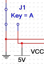
In dealing with digital circuits, it is often convenient connect digital inputs to an interactive SPDT switch and VCC (or any level of CMOS circuit is in) and ground as I did here. This gives you the ability to interactively control parts of the interactive test circuit...
Kind regards
Patrick Noonan
Business Development Manager
National Instruments - Electronics Workbench Group -
My client has 2 SG300 - 52p and 5 SG300 - 28 p. We have installed a VoIP telephony system earlier this year. At the time of installation, we placed the phone on the native VLAN 1 System. Now, they want to pass the phone system to a new VLAN, because their class C subnet is running out of addresses. DHCP is managed by their Active Directory and their router/firewall is a box to sort out. The SG300 switches have a basic configuration only.
To move the phone system to a new VLAN, I created 20 VLAN on each switch. I then turned on VLAN auto voice. I have all the ports on each switch setting on the trunk. Computers are plugged into the back of the phone. I then created a virtual interface in the box to unravel for VLAN 20. Box unravel also manages DHCP to the new VIRTUAL LAN. Active Directory is always manage DHCP for VLANS native.
I ping from each switch to the bridge of the new VLAN. Since each computer I can ping the gateway and on the new LAN VIRTUAL phone system. However, phones will not seize an address on the VIRTUAL LAN and when they have the static value, they cannot communicate with other devices on the VIRTUAL LAN.
Any help would be much appreciated. I don't know what I'm on.
Here is an example of part of a switch configuration to work with Zultys phones where voice VLAN is 100 and data VLAN 10:
database of VLAN
VLAN 10,20,100
output
ID of the vlan 100 voicesinterface fastethernet1
Description "RCP and voice."
switchport trunk allowed vlan add 100
trunk switchport vlan 10 native
!
interface fastethernet2
Description "RCP and voice."
switchport trunk allowed vlan add 100
trunk switchport vlan 10 nativeIn your case, you need a trunk port with 20 VLAN Tag on your firewall (or an access port to a separate physical port on VLAN 20. The default gateway served on the phone (or put statically) should be the interface on intellectual property. Then, you can also allow routing inter - vlan for admin access or MXIE if you use.
One thing to note on Zultys is by default I think the device profile disables LLDP, but on phones, it is enabled out of the box. For the first time that a phone downloads its config from the Zultys it can turn of LLDP unless you have checked the box to keep it on.
-
Subject of the vlan voice SRW224G4P
Hello
I have configured the SRW as vlan, use vlan for voice 212, 348 for data and communicate with cisco IP Phone.
database of VLAN
VLAN, 210-216 345-348
output
ID of the vlan voice 212!
!
interface fastethernet1
activate the storm control
Storm-control broadcast level 10
Storm-control include multicast
maximum port security by 10 points
port security mode max-addresses
port security throw trap 60
spanning tree portfast
switchport trunk allowed vlan add 212
switchport trunk vlan native 348
macro description ip_phone_desktop
! next order is internal.
macro auto smartport dynamic_type ip_phone_desktop
!but when I show vlan voice,.
It shows:
=====================================
1ASW01 #show voice vlan
Manage the VLAN voice State is automatically triggered
Operational status of VoIP VLAN is enabled in auto
Best Local Voice VLAN ID is 212
Best Local VPT is 5 (default)
Best Local DSCP is (by default) 46
Concerted VLAN voice is received from the 34:62:88:73:05:c9 switch
Concerted VLAN voice priority is 0 (static source active)
Concerted Voice VLAN ID is 216
Agreed VPT is 5
Agreed DSCP is 46
Voice VLAN agreed last change is 3 May 13 05:06:31=====================================
I don't know why the vlan 216 became the vlan voice?
I tried changed the build-in macro settings,
auto macro of the built-in parameters ip_phone $native_vlan 348
auto macro of the built-in parameters ip_phone_desktop $native_vlan 348but the system could not change the value of $voice_vlan.
How to fix?
Hi Skywings,
So I think the above output is after the change, right? If this is true, it seems that something was wrong during the configuration process. Process of VLAN automatic voice has two main phases where one is related to communication between the switches and other Cisco infrastructure devices and synchronization of voice VLAN ID. The second phase is related to the identification of the end device as phone. What I see in your case that the first phase has failed somehow the voice VLAN ID is different from locally configured. Can you share with me your race and also start-up config more CDP neighbors? You can use private message.
Kind regards
Aleksandra
-
I'll put up a D40 Digium Switchvox PBX phones and switches Cisco SG200. The PBX is no not any COP or LLDP pub so I don't expect the switch to automatically determine the voice VLAN ID and I need to manually set. How can I configure the switch manually to publis the voice VLAN via LLDP-MED? I've been tinkering for hours and may not include the TLV voice in packets. Be able to help?
Thanks in advance,
Paul


At the present time, my switch is configured by default vlan 100 and all ports as 100u. When you connect a phone to any port, it is dynamically assign the vlan 1. Also note that I created the vlan 1.
-Tom
-
call of CUCM to the router voice FXS thanks CUBE problem
Hello
We had a problem in our test environment:
- - - - Analog telephone When we on the g711 codec, both directions of appeal are ok.
When we put the codec for g729r8, appeal from analog to IP has no problem. But for reverse, the analog phone can ring but will be disconnected after a few seconds. Before the call is disconnected, we find that the codec is "pre-ietf g729" using the command 'show call active voice brief' on the CUBE.
The configuration of the CUBE and Router (FXS) voice is attached. Really appreciate your advice.
Thank you!
Eric
It seems that the analog phone only supports pre - itf g729 format...
Unfortunately this codec format is no longer supported on any ios...
http://www.Cisco.com/c/en/us/support/docs/voice/h323/14069-codec-complexity.html#pre_ietf
You can try your luck and see if this pre - itf is available on ios, but I doubt it. You will need to have them on all your dial peers.
maui-vgw-01(config)#dial-peer voice 100 voip maui-vgw-01(config-dial-peer)#codec g729r8 pre-ietf
The pre-ietf in this command option is not supported in Cisco IOS release 12.2 and later.
Maybe you are looking for
-
software installation problem left 3rd after the recovery procedure
I had the software installed on my laptop which worked well, but I had to run my laptop recovery disk,I saved most of my stuff to a USB but when I try to install a special software I get message "this application is registered to John (me)", but when
-
Web-camera on Satellite A300 problem - 10 c
Hello!!! I have a laptop Toshiba Satellite A300 - 10 c. Problem with the webcam! OS WINDOWS 7 ULTIMATE X 64Everything downloaded from the firewood with an official site! and when I turn on the room gives me: * the webcam is unplugged or defective. Ch
-
I have sign up for dip test 3 G motorcycle
I understand the Motorola only two weeks feedback network that excluded that I was invited to test the Android 6.0 on bike g 3
-
No sound. HP pavilion g series
the sound on my hp pavilion g series has stopped working even with headphones. This happened after my computer automatically
-
HP Officejet Pro 8625 cannot change the order of printing back to the front and want to change