Configuration of the switch SGE2010P
I am facing a problem during the installation of the switch SGE2010P with UC560. There are two switches in a SF300 and SGE2010P site. The SF300 works very well. But the SGE2010P switch is a problem. I connected the UC560 to the SF300 directly and connected SGE2010P to the SF300. In the two switches, all ports are trunk, not tagged vlan data and tag vlan voice. Switch SGE2010P is offline. Unfortunately, the phones don't work switch not which are connected to SGE2010P. Then I started shooting poorly, not marked all ports which phones are connected only to the voice vlan (vlan data excluded) and set the same ports to be the access port. Set the STP priority to zero. Now some phones work some are not. Can someone suggest what to do to fix this?
Hi sham, by default the EMS classic switch short tree covering weight. This switch to RSTP. Secondly, you may need to manually set the fast port on all ports. Spanning interfaces of the tree then set the edge port on instead of auto.
You said that all ports are given vlan not identified, voice vlan tagged, if that's the case, that your configuration of vlan is made. Assuming that the SF300 wearing exactly what you did on the EMS.
In addition, you mentioned that the EMS is autonomous, check again please. If you use port 24 or 48 so that in the stacking mode, these ports do not work.
-Tom
Please mark replied messages useful
Tags: Cisco Support
Similar Questions
-
Update the Configuration of the switch switch 2.1 Executive to 3.5
Hello world
I tried the switch 2.1 update Executive to 3.5 and have known, that my configurations have stoppped working. To me, it looks like 3.5 dislikes my IVI configuration for switching modules.
The function check in MAX tells me that the PXI cards are not available. The first page of the configuration of the switch shows no configuration / terminal blocks.
Because the configuration consists of nine matrix with lots of report cards, I would really appreciate a way to properly import the old configurations (xml files are available)
Any ideas?
See you soon
Oli
Hi Oli,
Yes, there was a major change in the Switch Executive 3.5 - it now uses for switching NI DAQmx calls material. There is a KB document the upgrade process a simulated configuration from an earlier version, but of course, you can try the steps that make sense, too:
Import of NI Switch Executive 3.0 and previous virtual devices in OR Switch Executive 3.5 and later versions
http://digital.NI.com/public.nsf/allkb/1D1099A85B156FA68625778500787444
However, I have noticed that the KB Editor uses a configuration file to .txt instead of the .xml you have. I see two options here: first of all, if you have even an operating system with Switch Executive 2.1, you could probably export settings in the form of text or you can try to modify the .xml file manually to resemble the layout of the text (probably a lot of work, you would have to learn the structure of the text by trial and error using newly created Switch E.g. 3.5 configurations...)
Best regards
Sebastian
-
Configuration of the switch of the NAC
Hello!!
I bought a NAC server and a manager of the NAC, to centrally manage the vlan where users connect to based on authentication.
I have several sites, but the NAC server will be at Headquarters.
When a remote user authenticates, NAC must configure the user switch port for the vlan right.
What is an out-of-band solution?
Do need me a specific license for out-of-band?
Best of look,
Miguel Amaral
Hello
It's the same pattern: Yo uneed 2 licenses, one for the CAM and the other for CAs.
One cam sets the number of cases you can add.
That case defines how many users is supported.
So either the CASE PAK has been lost, or never bought.
In both cases, you will need to contact the entitiy that sold devices and demand for the PAK CASE.
HTH,
Tiago
--
If this helps you or answers to your question if it you please mark it as 'responded' or write it down, if other users can easily find it.
-
Configuration of the switch...
Hi guys
I'm including a basic network (grouping of NIC design) using two network adapters for all communication on some ESX 3.5
my questions are:
1 I kept any configuration especial on the physical predisposees as trunk? especially for vmni4 and vmni5?
2. What is the NIC Teaming on ESX because I want the two active network cards: Load-balancing, failover network detection
Please let me know what should I have in here

Thank you very much
Not exactly. Aggregation of links work properly, make sure you use hash of intellectual property on the ESX vSwitch/portgroup config and src-dst-ip on your switch. Without it, no 'load balancing' occurs.
-KjB
-
No menu item of the Security Configuration on the switch of the device for ExternalEmbeddedDevice
Despite the use of NullAuthenticationProvider works as expected, I would try to sign a request (minimum profile) and deploy it in my RaspberryPi, but according to guide installation and Applications running on the Pi Board of raspberry , I'm stuck in the method #1, Point 8, since in the window selector device whenever I do a right-click on EmbeddedExternalDevice no article "Security Configuration... '. "is displayed in the context menu. Of these elements is frequently seen by the same operation on other devices (EmbeddedDeviceX and Qualcom_IoE_Device).
Any idea?
It seems a manual edit of _policy.txt is only an option for the RPi. The documentation is not in this part. EmbeddedDeviceX and Quacomm_IoT_Device are the emulators where all configuration files are on local and accessible file system since SDK.Netbeans.
-
Snort - configuration of the switch - sniffing physical and virtual
Hello
There was a bit of discussion on this topic already and I read all those, but I'm still lost as to whether I want to do is possible and how. I need to have capability of IDS in my vmware environment and physical environment switching.
1. that being said, I don't know where to put snort.
2. I know that I can paste snort on a virtual machine and give it an interface to each vswitch that promiscuity has been traffic on these vswitches, but which is the best way to do it?
3. how to get traffic physics switching down to a virtual machine? Is it still possible?
I'm on 3.5 and using Foundry switches if it matters.
The other idea I have is to not worry about this and paste my ID in the physical environment, since all traffic inter - VLAN should through the firewall anyway that is on the physical environment of switching. This protect me from knowing of vm - & gt; VM attacks however.
What is everyone think about this?
Hello
It's the kind where I was at. The other problem I have is that I need to activate on the whole portgroup or vswitch promiscous.
Only on the portgroup never the vSwitch.
This means that any host in this portgroup can promiscoulsy listen on a map network within this portgroup, right?
That's right, but now you must periodically check the portgroup to ensure that none of the United Nations that allowed VM is on the portgroup.
> As a dashboard that is able to read in several analyzers to snort all the recommendations?
There are a few web based ones. I would check snort.org... I used 'base', but is no longer directly use SNORT. It is integrated into my FWs now.
Best regards
Edward L. Haletky
VMware communities user moderator, VMware vExpert 2009
====
Author of the book ' VMWare ESX Server in the enterprise: planning and securing virtualization servers, Copyright 2008 Pearson Education.
Blue gears and SearchVMware Pro items - top of page links of security virtualization - Security Virtualization Round Table Podcast -
Best practices of priority network traffic at the switch
What is usually the best way to prioritize the specific traffic a VLAN specific?
I work with the differentiated Services to match the traffic of a VLAN specific and assign a queue of 6 switch to give traffic a higher priority than normal traffic. But I'm not sure that with this configuration. I red on the priority of traffic from the switch but I didn't understand any of this I think.
The police are certainly working. In the web interface, I see that are packages offered for the DiffServ, according to me, I'm missing something...
Config:
Policy-map {policy name} in
class {class name}
Assign-queue 6
output
interface port-channel 1
service-policy in the {policy name}Just a brief update: I think that my setup works fine. I figured out that the ping response delay has more to do with the terminal and then with the configuration of the switch :)
-
LACP Configuration for Distributed Switch - vSphere 5.5
I'm trying to set up the switch distributed in a new lab, but I have a question on how to properly configure the port offsets.
If I have a collection of servers, each with two uplinks to a physical switch, how to properly configure the LACP lag? All ports on all of the servers are part of the same GAL, or should I create a different OFFSET for each new host?
For example:
Lets assume 16 servers. I create a single GAL on the DSwitch, mapping of all physical links 32 rising at the same OFFSET, then replicate the physical switch configuration? Or should I create 16 different gal, one for each pair of uplinks on each host server?
It seems strange to me that I should set up all servers on the same SHIFT, containing the uplinks for different physical host computers.
Aaron, looks like you got it. You can think of the LAG configuration on the switch distributed as a profile of the EEG applied to each host. The physical switch upstream is configured with an OFFSET for each host.
-
The Switch configuration and Wi - fi router in the same network
Hi team,
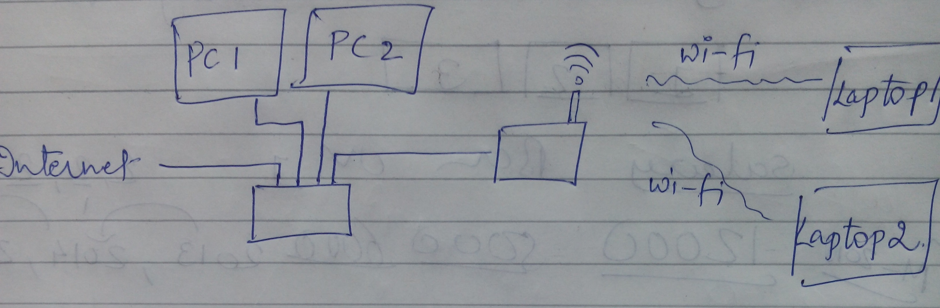
I have here is the configuration currently as below in the image. To describe the same internet cable is connected to a Cisco switch, which is connected to the PC in LAN (wired). A switch output is connected to the entrance of the wireless router Netgear Nighthawk AC 1900 Smart model of WiFi router # R6900. Wireless devices (laptop) are connected by the router.
Each device has internet access. However, I am unable to run software LAN or unable to share any file of devices connected to the switch to the connected wireless devices. I can't ping any device the device wireless wired.
Can anyone suggest what are the settings that I should do or what are the steps I should follow that will make wireless and wired devices in the same network.
PS Plus early I tried the internet connection to the wireless router and then out of the router to pass, which has solved this problem. But slowing down my internet speed in wired devices. So, is it possible to have all devices in the network even with the current configuration?
Thanks in advance.
Best,
Hardik
I made wi - fi router reset hardware and configured in Access Point mode, that solved my problem.
-
Can I configure NISE with a switch of party - if the switch is not installed?
I've never used NOR Switch before Executive - we hope to use it on a new project.
We do not have equipment at the moment - we will use a Pickering 40-540-021 '132 x 4' switch.
I would like to configure NI Switch Executive before Pickering delivered cards, is it possible? I get an error when I create the NI Switch Executive virtual device. Seems that MAX is trying to communicate with the switch card before allowing me to configure routes/exclusions/groups etc..
Here's what I've done so far:
-Install the drivers of Pickering.
-To the MAX (v5) I have setup a session driver IVI and logical name.
When I try to create a new NI Switch Executive peripheral virtual, I add the logical name of the switch, click [next] and get the NISE error...
"An error occurred so they were trying to access the devices PROJECTSWITCH. The primary error: unknown status code (Hex 0xBFFA400C).
I see that a virtual device is created with no logical switch assigned. I get the error even if I try and add a logical switch manually to the virtual device NISE.
Is it because the switch Board is not available for the system? Can I configure the routing/groups/exclusions without the device being mounted physically switch?
Thank you
Alan
Alan.
Seems that MAX is trying to communicate with the switch card before allowing me to configure routes/exclusions/groups etc..This should be the expected behavior. NEITHER Switch Executive tries to communicate with the instrument before allowing you to configure routes to ensure that there is no problem that would affect the operation of the Switch Executive. In your case the pilot trying to communicate with a non-existent device.
I would like to configure NI Switch Executive before Pickering delivered cards, is it possible? Can I configure the routing/groups/exclusions without the device being mounted physically switch?
It is possible that all compatible IVI devices should have the ability to simulate.
It seems that you have configured your session of IVI driver incorrectly for a simulated device. I try and make sure that in the session driver, under the 'Général' tab, select the drop down menu to "Simulate with" and select 'Specific driver' and then click 'Save the IVI Configuration'. This will return the Pickering driver selected in the 'software' tab and simulate a device. This should allow you to create a virtual device NI Switch Executive and develop and test the code on the simulated instruments.
I would like to know if you have any other questions.
-
IviSwitch loses value when sending, "configure the switch" configuration = TRUE
Hi all
We are currently assessing Teststand 4.1 with a multimeter keithley 3706 switch system.
After a first enthusiasm, thinking this tool with the meter switch fits perfectly our needs, real life seems difficult.
Between several other problems, we must say to the device, the channel "s1com1" and "s1com2" are strings of configuration.
Configure the teststand step: change the switch step IVI-> IVI, switching, configuration switch: channels "s1com1" Configuration = True
led to observable in both actions in Ni Spy:
GetAttributeViBoolean (..., "s1com1", _IS_CONFIGURATION_CHANNEL, VI_FALSE)
SetAttributeViBoolean (..., "s1com1", _IS_CONFIGURATION_CHANNEL, VI_FALSE)
manually call to this function of the interactive a CVI fp class works as expected (the VI_TRUE updated)
Is there any hint that we could do wrong? Currently, we are just before writing wrappers in cvi and jump all the wonderful Types of IVIStep in teststand.
Looking forward to any comments
David Clus
David-
This would have the same problem we discovered recently in our internal tests. For the problem that we found, we will probably include our fix in a next corrective patch. You can check if the problem persists if you change your locale in English in the control panel? If the problem no longer occurs, can you use this as a workaround for now?
-
The switch configuration of 6500 catalyst for IPS Inline the METHOD works
I understand how to configure the switch Catalyst 6500 so that the monitoring of ports are access ports in two VLAN separate operation online.
However, I don't see any document that describes how the desired VLAN traffic gets forced through the IPS.
"Promiscuous" mode, you can use copy/capture VACL and forwards traffic wished the METHOD of analysis. I don't see how to get traffic desired through the IPS.
Note that the 6500 host is running native SXE IOS 12.2 (18).
Thanks for any help.
A transparent firewall is a pretty good comparison.
Say you have vlan 10 with 100 PCs and 1 router for the network.
If you want to apply a transparent firewall on this vlan you can put not just the Firewall interface on vlan 10. Nothing would go through the firewall.
Instead, you need to create a new vlan, say 1010. Now you place the Firewall interface on vlan 10 and the other on the vlan 1010. Nothing is still going through the firewall. So now move you that router from vlan 10 to vlan 1010. Everything you do is to change the vlan, IP address and the mask of the router remain the same.
The firewall transparent bridge vlan 10 and vlan 1010. The SCP on the vlan 10 ae is able to communicate and through the router, but must go through the transparent firewall to do.
The firewall is transparent because there no IP Route between 2 VLANS, instead, the same IP subnet is on the VLAN and the transparent firewall ensuring the beidges between the 2 VLANS.
The transparent firewall can do firewall between the SCP on the vlan 10 and the router on vlan 1010. But PC has vlan 10 talks for PC B on vlan 10, then the transparent firewall does not see and cannot block this traffic.
An InLine sensor is very similar to the transparent firewall and will fill between the 2 VLANS. And similarly an InLine sensor is able to monitor InLine between PCs traffic on vlan 10 and the router on vlan 1010, but will not be able to monitor the traffic between 2 PCs on vlan 10.
Now the PC on the other vlan and the router on a virtual LAN is a classic deployment for the sensors online, but your VLAN need not be divided in this way. You can choose to place some servers in one vlan and desktop to another vlan. You subdivide them VLAN to whatever the logical method for your deployment.
Now for the surveillance of several VLANs the same principle still applies. You can't control traffic between machines on the same vlan. So for each the VLAN that you want to analyze, you will need to create a new vlan and divide the machines between the 2 VLANS.
In your case with Native IOS, you are limited to only 1 pair of VLAN for InLine followed, but your desired deployment would require 20 pairs of vlan.
The IPS 5.1 software now has the ability to manage the 20 pairs, but the native IOS software doesn't have the ability to send the 40 VLAN (20 pairs) to the JOINT-2.
Changes in native IOS are in testing right now, but I have not heard a release date for these changes.
Now cat BONES has already made these changes. So here is a breakdown of basic of what you could do in the BONE of cat and you can use to prepare for a deployment native IOS when it came out.
For VLAN 10-20 and 300-310, you want monitored, you will need to break each of those VLANs in VLAN 2.
Let's say that keep us it simple and add 500 to each vlan in order to create the new VLAN for each pair.
Therefore, the following pairs:
10/510, 511/11, 12/512, etc...
300/800, 801/301, 302/802, etc...
You configure the port to probe trunk all 40 VLAN:
set the trunk 5/7 10-20 300-310 510-520 800-810
(And then clear all other vlans off this trunk to clean things up)
In the configuration of JOINT-2 create the 20 pairs of vlan inline on interface GigabitEthernet0/7
NW on each of VLAN original 20 leave the default router for each LAN virtual vlan original to the vlan 500 +.
At this point, you should be good to go. The JOINT-2 will not track traffic that remains inside each of the 20 VLAN original, but would monitor the traffic is routed in and out of each of the 20 VLAN.
Due to a bug of switch, you may need to have an extra PC moved to the same vlan as the router if the switch/MSFC is used as the router and that you deploy with a JOINT-2.
-
I have a demonstration kit that includes a WLC 2106 and WAP 2 1252. I have configured the WLC correctly (I think) and the WAP 2 can contact the WLC when they are plugged directly into the WLC and I can connect my wireless laptop. I want to spend the WAP directly connected to the WLC to a core switch Cisco 3560 G. No one knows what port on the 3560 settings should do or where I can look. I have configured the switch ports:
Interface GigabitEthernetX / X
switchport trunk encapsulation dot1q
switchport trunk allowed vlan 212,214,215,901
switchport mode trunk
but when I plug in it do not access the WLC.
Happy, it was a simple problem to solve :)
-
KVM access - needed to configure the switch upstream?
I'm short on time, and I'll put up a UCS solution tomorrow for the first time. I have a feeling I'll have problems of access to the console KVM IP subnet.
Do I need to configure the switch upstream so that the KVM access to the work of the management of VLANS? The subnet KVM stands by the management subnet. I could also set to the same subnet. What is practice here?
KVM IP subnet must be in the same subnet as the management IP addresses you assign to each fabric interconnect. This is due to the KVM using the versus network ports the FEX upstream to FI ports.
Hope this helped...
Richard Pugh
-
Aggregation of links ESXi requires the configuration of the physical switch?
Hello
I have two physical servers that I'll put up with ESXi. Each server has eight physical network cards. My plan is on each server to use:
-2 management - connected to vSwitch0
-2 for VMotion - connected to vSwitch1
-2 for iSCSI - connected to vSwitch2 (I'll use a SAN)
-2 to access VM network - connected to vSwitch3For each pair, a cable should be connected to switch1 and the second would be plugged into switch2.
The switches are HP A5120 which are stacked into a big switch with RFID. for example I have a 'big' switch which, if one of the two physical switches dies or is turned off, would cause the 'great' switch to lose half of its ports. In this way, all four networks are expected to continue to operate even if a switch "dies."
All the information I found online said that ESXi can have two physical cards attached to a unique vSwitch and can then do things smart for redundancy (in which case a physical NETWORK card dies) and load balanacing.
However, while all the guides tell me how to configure it on ESXi, I'm still not sure if I should combine the two cables on the physical switches.
So, my questions are:
(1) in order to get the NIC or balancing working in ESXi, redundancy do I have to combine two physical ports that will connect connect two physical ports that connect to the vSwitch?
(2) with the consolidation of NETWORK cards, I see how to have an active adapter for the management network, and an auxiliary card works fine, but for the iSCSI network, I wouldn't have only two active adapters for double the bandwidth?
Any ideas would be much appreciated.
Thank you.
(1) in order to get the NIC or balancing working in ESXi, redundancy do I have to combine two physical ports that will connect connect two physical ports that connect to the vSwitch?
No, there is no need to configure etherchannel/LACP but this will depend on the type of load balancing, you click on the ESXi host - if you use by default, you don't need to configure Etehrchannel/LACP since traffic for each virtual network interface will be only com ove a single physical port, but you will always have the reiciliency to the case where if one of the physical NIC fails traffic then released the remaining port
If you select the hash of the IP load balancing, you must then implement Etherchannel/LACP on your physical switch since traffice can come form any physical port in the team.
(2) with the consolidation of NETWORK cards, I see how to have an active adapter for the management network, and an auxiliary card works fine, but for the iSCSI network, I wouldn't have only two active adapters for double the bandwidth?
Onece well once again it will depend on the Load Balancing method, you select, but you will never be able to create links physical ports to get all of the 2 GB =
I also moved it to a more appropriate forum-

Maybe you are looking for
-
Hi, after plug the cable on my phone i 6 to connect with my mac book air, nothing appear on the mac book. Seems like it can't detect the file i phone 6. I want to export my photos and do the upgrade version. Current situation is nothing exportable ph
-
I keep getting ads I don't want help pls
every time I click on a part of a window it keeps popping up with an ad.I'm getting sick and tired of it and I don't know what to do.do you?
-
Windows XP install Service Packs 1, 2 and 3
I have a secondary old Dell desktop PC. The Intel graphics chips and drivers were originally produced by Intel only for XP or XP Pro for this configuration of office. I had to reinstall my XP Pro HARD drive problems. XP Pro installed OK, no problem.
-
After that upgrade to 8.1 HDMI port has failed. Followed the instructions to fix the BIOS and graphice driver; HDMI - works however Silverlight no longer works with DMS. Get the 6036 error in Silverlight which is the display device driver certificat
-
I have a Compaq with vista home basic 32-bit preinstalled and I want to upgrade to 64
I have a Compaq with vista home basic 32-bit preinstalled and I want to move to 64-bit is it possible to use the sticker on the side of the case to just upgrade the same version of windows, but just for the 64 bit for windows vista home basic 32-bit