Continually acquire analog input, internal clock, break, Multiple device
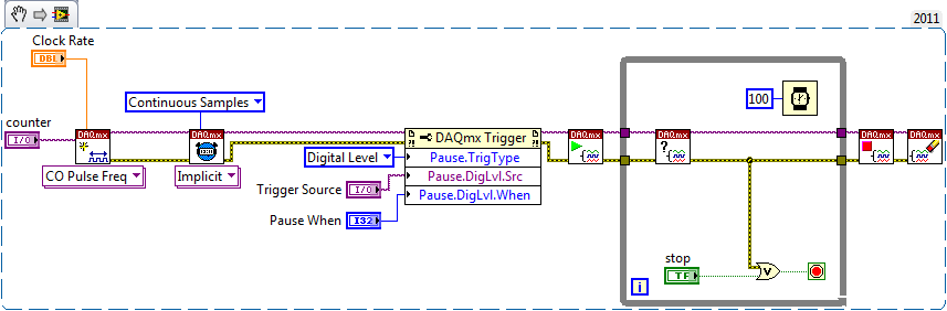
I have a PXI chassis with 6 cards SMU-6363. I want to acquire data on the channels of each SMU-6363 map continuous AI, using the internal clock for timing. I need to use a trigger to pause reading of a DI on one of the cards SMU-6363 for a break and to reactivate the acquisition. I came across this example: https://decibel.ni.com/content/docs/DOC-12256/ , but keep getting error-201019 DAQmx start task "trigger break is not supported in a task to more devices. To configure the start of break in a multi-device configuration, you must use no more than one device per task and route manually clock in demand signals. »
The problem is that the configuration of I is made during execution by the operator. Sometimes they want to acquire data on one HERE through all 6 cards SMU-6363, sometimes they want to acquire data on each channel of AI through all 6 cards SMU-6363. What makes the task definition until manually route clock signals between devices for each rather difficult task.
Is there a simpler way to solve this problem?
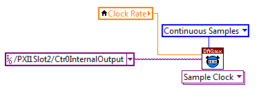
Set a task to output counter - something like this:
Next, configure your task of analog input to use the sample clock output of the meter:
Best regards
Tags: NI Hardware
Similar Questions
-
Using the DAQ USB-6009 meter and an analog input voltage at the same time.
Hello
Currently, I'm reading the two channels of voltage with the USB-6009. It happens that one of the channels is the output of a digital coder, and it would be much easier to use it directly to the PFIO entry that is defined as a counter. The problem I am facing right now, it's that I can't use the DAQ Assistant to use the analog voltage to a channel and the digital channel counter at the same time. Once I put the DAQ Assistant to read the input from analogue voltage, I won't be able to add analog inputs. And as I put the DAQ Assistant to use the PFIO as a counter, I can add more entries to read analog voltage is.
I wonder if it is possible to solve this problem using the lower level data blocks? Another solution would be to read two channels in analog input voltage and that the use of Matlab to process data resulting from it, since I was not able to do the counting to work simultaneously with the acquisition in Labview to impulses.
Hope you guys can help out me.
Thanks in advance.
Using a simple wizard of DAQ is incorrect. You need one to acquire analog inputs and one for the meter.
-
PCI-6110 to change analog input range
The analog signal I want to measure is 24 volts and the maximum PCI 6110 is Volt.However 42, analog inputs that appear in the device under device NOR-DAQ traditional (old) configuration is 10 volts (single selection). I'm using LabView 7.1, DAQmx 8.6 and there is no function for allowed me to modify and change the analog device input range (Please find the print screen of the attachment). Can I know how can I change the analog inputs range?
I think that's what you're looking for:
S how to set up a data acquisition card series for the entry level so it does not Clip?
You must set up an appropriate gain so that the other ranges of voltage is displayed.
In addition, you can post on the forum instead of Labview data acquisition in the future, because the chances are that you will get better/faster responses there

Good luck!
-
read the multiple analog inputs at the same time
Hi all
I use USB-6001 and want to develop an application to multiple tasks in C++. I try to read several analog inputs at the same time, but got some errors. To put it simply, I copy one of the sample code to read in analog data in a channel, and then turn it into function. Then I call this function to thread with the names of different poles (for example Dev1/ai0, Dev1/ai1) and I come across this error:
"The specified source is reserved. The operation can not be specified such complete"code of State-50103
I have search the forums, this may be because I use the hardware timing in this function, and this material timing cannot be used simultaneously by multiple tasks. I may have to put all the lines, I want to read in a single task (such as Dev1 / ai0:1). This way I can read two lines at the same time. However, when I try this, I encounter another error:
Status code "buffer is too small to contain the data read" - 200299
So here is my question, what should I do if I don't want to read the multiple analog inputs at the same time? Is the thing that hard time cannot be used by several true task? If I have to read several lines to a single task, how to set the settings?
-
I use an analog input on a PCI-6224 and are having problems with the clock source
I use an analog input on a PCI-6224 and are having problems with the clock source. I'm trying samples of 16 different analog inputs very quickly. I have the sample mode: Timed Single Point material. The rate, that I am running is the maximum (250 kHz (15625Hz per channel)). I left the default clock source and trying to taste several times. The analogue input works for a short time (2-3 seconds) and then everything stops. I'm doing something wrong or is there something I'm missing? Any advice would be great.
That's how you samples using the sample clock clock. If you see a delay then something is wrong with how you track/data visualization.
Single point NI the hardware is for PID control with a real-time operating system.
-
Registration of the analog inputs in continuous (Clipping)
Material:
(1) USB NI CDaq-9174 chassis
(2) NEITHER 9234 Analog Input Modules
(1) digital input module 9402 OR
Goal/Requirements:
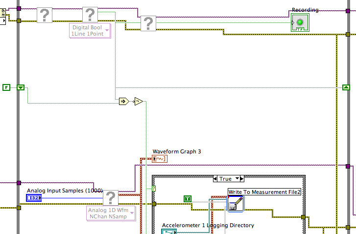
To read the analog inputs continuous only in digital input is "high".
Problem:
Timestamp in log file prooves that logging is not continuous. It seems that the first seconds of 0.6 of every second is recording, I guess the other 0.4 is used to write custom? I can't use VI SignalExpress for this application because logging must be triggered by a high digital input.
File is attached. Thank you all!
To detect changes in the digital input, you need to compare the current value to the previous. The easiest way to do this is to plug the output of digital playback on a shift register. The Boolean function involves will tell you when a transition has taken place. See the central part of the image below. If you exchange the true and the false case of case structures, you not the inversion function. Look at the help file for more information on what the function actually implies.
You must also change the wiring of the name of input for writing custom file FIle.vi so that the name is automaticlly changed. Depending on what you want the naming system to be, that it can be simple or rather complicated.
Lynn
-
Synchronize the clocks of 2 PCI cards for analog inputs with e/s digital reference
I'm trying to synchronize the clocks of reference of 2 PCI cards so that the analog inputs are synchronized. However, my appilcation has also digtial e/s on two cards, and who apparently made the mistake DAQmxErrorResourcesInUseForRoute_Routing. This discussion describes a similar problem, but the solution was to just put the reference clock to the slave device, who had no other tasks running on it, so what mine does.
Is there way I can synchronize the clocks of refernce without interfering with the digital I/o?
Thank you!
PS: My application is in C++.
The reference clock is really a lower-level component that is shared by all resources on a given device. All tasks on a given device must use the same reference clock. So if you use DAQmxSetRefClkSrc for a task, you can use it to set the same value for your other tasks.
Best regards
-
Establishment of a reenclenchees analog input on M-series DAQ in LabWindows
I am creating a task entry analog hardware triggering which will acquire N samples whenever I give a hardware trigger with an acquisition of data USB-6229. As far as I can tell from reading through previous posts, the Council does not natively takes in charge of responsibilities reset like that, I am supposed to create a counter that will be used for the internal clock for a second task (probably a task of acquiring continuous). My problem is that it is not at all clear how to do this. I tried to go to MAX and create output of meter, but all the options for the shutter button 'start' are grayed out. In addition, I don't know how to put the impulses in French - 1 pulse, continuous pulses, etc. Which of these counters will be hardware-redeclenchables? Documentation I've found so far for most of the offers with LabView and I can't really understand how tasks are configured based on the pictures that they show.
Hi Paul,.
Try the following DeveloperZone:
DAQmx - I redeclenchables using redeclenchables counter
I don't know why the files have names-ambiguous, in my opinion, the one you want is called 3018.zip.
Best regards
-
What is the minimum response of analog input, through DSP online, output analog time?
Hello experts!
I want to know if it is possible to get a very quick response latency (~ 1 ms) sound recording (analog input), through online registration (DSP online), the presentation of his (analog output) processing, by using the DAQmx programming codes. My system of NEITHER includes NOR SMU 8135, SMU 6358 DAQ Multifunction controller and SMU 5412 arbitrary signal generator. I also have access to the latest version of Labview (2015 Version) software.
My project is on auditory disturbances, which inovles record vocalizations, manipulating the recorded vocalziations and then present the manipulated vocalizations. My current idea of how to achieve this fact triggered output voltage after reading the input using DAQmx Read samples. DAQmx Read output is filtered online and then passed as input for the DAQmx writing for analog output. For purposes of illustration, examples of code are presented below. Note for simplisity, codes for the trigger part are not presented here. It's something to work in the future.
My question here is If the idea above should be reaching ~ 1ms delay? Or I have to rely on a totally different programming module, the FPGA? I am very new to Labview so as to NEITHER. After reading some documentation on FPGA, I realized that my current hardware is unable to do so because I do not have the FPGA signals processing equipment. Am I wrong?
Something might be important to mention, I'm tasting with network (approximately 16 microphones) microphones at very high sampling rate (250 kHz), which is technically very high speed. Natually, these records must be saved on hard drive. Here again, a single microphone is shown.
I have two concerns that my current approach could achieve my goal.
First, for the DAQmx Read function in step 2, I put the samples to be read as 1/10 of the sampling frequency. It's recommended by Labview and so necessary to avoid buffer overflow when a smaller number is used. However, my concern here associated with the latency of the answer is that it might already cause a delay of 100 ms response, i.e. the time to collect these samples before reading. Is this true?
Secondly, every interaction while the loop takes at least a few tens of milliseconds (~ 30 ms). He is originally a State 30 late?
Hey, I've never used or familiar with the hardware you have. So I can't help you there.
On the side of RT, again once I don't know about your hardware, but I used NOR myRIO 1900, where he has a personality of high specific speed for the RT where I can acquire the kHz Audio @44 and process data. Based image processing is ultimately do the treatment on a wide range of audio data you have gathered through high sampling frequency and number number of samples as permitted by latency, please check this .
I lost about 2 weeks to understand host-side does not work and another 2 weeks to understand the even side of RT does not work for online processing (real time). Then, finally now I'm working on FPGA, where the sampling rate is 250 kHz (of course shared by multiple channels).
The complex thing with FPGA is coding, please check if the filter you want is given below as labview automatically generates some codes of some filters.
Most of them will work in 1 SCTL IE if your target has 40 MHz clock algorithm will run in 25 ns. That's what I was looking for, I hope you

See you soon... !
-
How to write constantly to analog output and read from analog inputs
Hi all -
I had a question about writing continuously to analog output reading simultaneously an analog input.
It's my first time to post a message to the community, so please let me know if I made mistakes.
I use Labview 2011 with a NEITHER-DAQ USB 6215.
I'm looking to generate a waveform and write it continuously in an analog output. It is then connected to an entry on the acquisition of data, where I am trying to sample the analog signal. (I realize, there is a system of trivial, but I'm hoping to build on it once I have run).
The task of reading from the analog input works fine, as I tested it in several other cases. I have a problem writing to the analog output.
For this task, I tried to follow the "Gen Cont Wfm Clck Int' VI to generate the wave form and start the task. I then try to write to the output of the analog timed loop. However, it does not seem to transmit a signal and doesn't give me any errors.
I have attached the VI but also a screenshot.
Please let me know if anyone has any ideas. I would really appreciate the help!
Thank you
Peter Borgstrom
We will review your tasks one at a time. First of all, the task of generation/Analog output Waveform. Generate you a waveform (I'm unsure of your VI if it is a fixed waveform or not) and send it to a defined output function to produce a waveform continuously, using N-channel and samples of N (where you set not these previously). You should not put this inside has timed loop, as the DAQ hardware has its own clock - if you simply put it in a while loop (with a stop to break out of the loop), the loop will call the function for the first points of N, wait until all N have been taken out, then call it again to another N points (up to what you press Stop).
Now, suppose that you have the output connected to a load voltage (say a decent resistance). You can wire the input terminals of your A/D converter through the same load and set up a similar analog input loop, running in parallel (i.e. in its own independent of the OD loop, while loop). You pourriez start together (with, say, a merged error since the initialization code line loops HAVE and AO become lines of error in "loops of sampling" described above), but you might want to delay loop (a little) the AI so that the OD has a chance to set the voltage before the bed.
I hope this helps.
BS
-
Two analog inputs of synshronized
Hello
I am using PCI-4461 and connection of two amplifiers in its analog inputs (AI0 and AI1).
I need the output voltage of the two devices based on time together; This means that the AI0 and AI1 must be synshronized.
And then draw the voltage v/s time in 2 different plots. This means that I need to split signals and analyze each channel separately.
Number of samples: samples of 200,000
Do you have an idea how do?
I've used extensions on the acquisition of data PCI-4461 to select multiple channels and in control, I selected several channels.
How do I continue to get the plots?
Thank you in advance,
Kind regards
Connect the waveform 1 d array to the array of Index entry. Drag down to get two outputs. Each output wire to a graph. The index entries start automatically to 0 if you do not need to connect something there.

Dividing is done with the function of Division. You just son of the waveform in an entry and a wire to another constant.
-
Synchronization of two inputs frequency meter with several analog inputs
Hi all
I'm relatively new to LabVIEW and I'm trying to collect data from multiple sources with calendar sync on the acquisition, but I can't understand. My problem is that I have two inputs frequency meter, an optical tachometer reading one pulse per revolution and a max flow meter machines with a 12000 k coefficient. I can't find a way to synchronize the calendar with my multiple analog inputs. I tried to first get the speedometer to synchronize with the analog inputs following the example linked here. (https://decibel.ni.com/content/docs/DOC-10785) So far every time I run it I get an error on the DAQmx read timeout or an error "several sample clock pulses have been detected" (see image). It seems if I slow the way to down to say 10 hz and make sampling rate ensure that the tachometer signal is more than 800-1000 rpm (13-17 Hz) before starting the VI then the program will run without error until the ROTATION speed is below this threshold, then the "sample Multiple clock pulses" error occurs. The code is attached below.
Does anyone know of a better way to synchronize the entries of frequency of the counter with analog inputs? I would like to have a VI that can display 0 RPM (and possibly 0 flow as well, but I think I need to understand the timing of a meter before I have add another, because it seems that I can't have two counters to the same task). Any help on this would be greatly appreciated.
LabVIEW version 13.0
Chassis cDAQ-9178 with NI 9401 for both counter inputs and NI 9205 for the analog inputs.
Thank you!
Richard
I know the error requires to restart the task at least (this particular error puts the material in a State that cannot be recovered from during execution of the task - I've been down this road before) but I'm surprised that you would have to delete and re-create the task altogether. And then I had to do this to workaround other questions in the past. It is awkward and should be considered a bug, if this is indeed the behavior.
Honestly, regardless of this bug, the way the material dealing with the situation of several sample clock edges makes measures of sampling frequency clocked essentially unusable for purposes of synchronization (in my opinion anyway) If you encounter a more slow than your sample clock rate. You are supposed to be "synchronization" of the measure, but it really no longer applies if you have to restart the task over and over again (if you must delete it or not).
Workarounds can get kind of creation (which isn't really a good thing). For example, you can configure a measure of implicit frequency to keep a buffer of frequencies and use a leader board task (source is the frequency signal, sample clock is the sample clock HAVE) to establish a correlation between the index of your buffer of frequency for singing HAVE sample clock.
Best regards
-
Analog input and contrary to the worksheet
Hello
I m trying to get an analog input (volts of a sensor) and a counter with an encoder. I ve long time looking for a solution and I ve already found some very useful examples that I ve used on the VI (thanks for that
).The program is very close to what I want, but there are still a number of things that I don't understand (I m very new with labview and I still Don t know exactly what I m).
-J' read in an example here that I should use "Single Point timed material" and use the "wait for next sample clock VI' to get samples always with a period fixed (rate). It's works! Before, I used "continuous sample" and it was a bit jitter. Well, could someone explain to me please what is the difference between continuous and timed, material and how the 'Harware Timed Single Point '.
-My second question is about the string formats that I receive on the loop of the wave. I ve tried with very different formats, but it doesn´t work as I expected. I have a format string like this on the 'Date Format VI': %S % 3u-online seconds with 3 decimals?
And on the format I have on the 'picture to a worksheet VI string' should I used %5.7f to get 5 decimals on the output (spreadsheet file). Why?.
What I m trying is to get the analog input with counter clock (I think I already do), given a graph and a file with lines of 3: 1 °-time with 3 decimals, 2 °-v with 5 decimals (positive and negative) and 3 °-position (positive and negative integer).
Software: Labview 2013, pilot DAQmx 9.8, Windows 7 32-bit
Material: NEITHER 6321 PCIe, Intel Quad 9550, 4 GB RAM
I hope that his undestable, I should learn some English to.
Thank you
Hello
Thanks again for the response. I tried to implement the code as you say, but it's always a mistake to time. I solve it with a timestamp.
The idea of a producer consumer loop was very good. After"a bit", I managed to solve it too. Here's the code.
Thank you
-
How to synchronize the analog input and the output of two different USB data acquisition boards
Hi all
I have two tips very different USB NI USB 6008 case, which I use to acquire the data (analog input) and a USB of NI 9263 is a output analog only site I use to route a signal (in this case a square pulse). The reason why I use the outputs analog 6008 is because I need to deliver negative tension and need the full +/-10 v range.
Looking at similar positions, I'm pretty sure that I can't use an external trigger or a common clock, I also tried to use the timed synchronization of the structures but no cigar.
I'm including a quick vi I whipped showing how the jitters because of the lack of synchronization signal. The OD of the 9263 connects to AI in the 6008 in this example.
I talked to a specialist in the phone and tols me that's not possible.

-
analog input and output synchronization
Hello everyone, I seem to have a problem of synchronization of the analog input and output on my M-series USB-6211. My request is quite simple. I want to the production and to acquire a sinusoid at the same time. Theoretically, I should have the same 4000 data points through the input and output channels. The reality, however, captured on an oscilloscope, shows that the analog output is off more than 4000 data points. The entry (acquisition) shows 4000 samples. Please see below an excerpt from the creation of task, timing and execution. I'm afraid that the analog input and output are not attached correctly. Do you see something suspicious? Thank you very much! The task was created: DAQmxCreateTask("",&inTaskHandle); DAQmxCreateTask("",&outTaskHandle); Analog output channel Configuration, with 20Ksamples/s: DAQmxCreateAOVoltageChan (outTaskHandle, physChanOut, ' ',-10, 10, DAQmx_Val_Volts, NULL); DAQmxCfgSampClkTiming (outTaskHandle, "OnboardClock", 20000, DAQmx_Val_Rising, DAQmx_Val_ContSamps, 4000); Configuration of the analog input strings: DAQmxCreateAIVoltageChan (inTaskHandle, physChanIn, "", DAQmx_Val_RSE,-10, 10, DAQmx_Val_Volts, ""); DAQmxCfgSampClkTiming (inTaskHandle, "OnboardClock", 20000, DAQmx_Val_Rising, DAQmx_Val_ContSamps, 4000); Set up the trigger: sprintf ("/%s/ai/StartTrigger", local_port, deviceName); DAQmxCfgDigEdgeStartTrig (outTaskHandle, local_port, DAQmx_Val_Rising); Output: DAQmxWriteAnalogF64 (outTaskHandle, (numberOfSamples * oversample), 1, 40, DAQmx_Val_GroupByChannel, input, & sampsPerChanWritten, NULL); Acquire: DAQmxReadAnalogF64 (inTaskHandle, 4000, 40, DAQmx_Val_GroupByChannel, readArray, 8000, & sampsPerChanRead, NULL); The tasks stop: DAQmxStopTask (outTaskHandle); DAQmxStopTask (inTaskHandle);
Hello
Change the finished continuous sampling method seems to solve the problem:
DAQmxCfgSampClkTiming (inTaskHandle, "OnboardClock", 20000, DAQmx_Val_Rising, DAQmx_Val_FiniteSamps, 4000);
Also, I wanted to say earlier to write 4000 samples:
Output:
DAQmxWriteAnalogF64 (outTaskHandle, 4000,1, 40, DAQmx_Val_GroupByChannel, input, & sampsPerChanWritten, NULL);
Thank you


Maybe you are looking for
-
How to use smart keywords in Firefox 34?
Where smart keywords in v34? I mean be able to assign keywords to a particular search from the address bar. For example I have "I" set to search Bing Images, "imdb" IMDB search value, etc.. I got different search engines set up, managed to change the
-
functions of YouTube works do not (such as adding to the playlist comment)
Hello.functions of YouTube works do not (such as adding to the playlist comment) has stopped working, they are still working for the same account on chrome or another browser. (when it happened I didn't update or downgrade programs, addons, plugins t
-
Apple tv 4 buffering on itunes
Apple tv 3 goes buffering movies very well from my computer but apple tv 4 stop the movie all the time. I'm wired directly to my home router with the two apple TV and my computer. I ran some new cables cat6 directly from the computer to apple tv 4 an
-
my game launcher has stopped working, tried everything but can get work someone help
-
DeskJet 6980: Deskjet 6980 do not e-mail or Adobe print
My printer displays the message "the selected printer is not available or is installed correctly. The printer is installed and will print documents. Not Adobe print there either. I went through the troubleshooting, I deleted and reinstalled, I unplu