Continuously measure and write waveform using PDM
Hi all
I'm doing my thesis by using Labview 2010 (since this is the only version currently available in University  ). I need to read and save data from the microphone (currently to simulate a signal because I need to make the program work first) then save and analise IT (has not reached this point yet). I tried to use the structure of the event in order to record and then play tdms files. But unfortunately it saves only a small piece, then I inserted while loop, so it will record continuously but the program is not responding after registration, I push and I can only manually close the toolbar it. Please does someone could help me or suggest that something since I'm not very good for Labview and any comment is welcome. Here's what I've done so now. I tried searching forums for a similar solution but did not find anything useful (some had a much newer version so I could not open). Thank you.
Hi and welcome to the forums,
The reason why you can not stop the waveform recording or exit the application is because you have the case of the events set to "lock the table until the end of the matter for this event" (in edition events). This means that LabVIEW will not respond to the user until the end of this structure of the event, but because you have the option to press the while loop stop to complete the structure of the event means that you have a blockage and abandon the VI.
The architecture of your application is not ideal - I highly recommend everything that takes a long time to execute within the structure of your event for the above reason (obviously you can uncheck lock as a quick fix Panel). I think I have a look at the design of producer/consumer model (events) (new... > model > frameworks) because it would be more appropriate for your application. You can manage your button presses in the structure of the event and have a state machine in the loop at the bottom for starting, running and stopping of your data acquisition.
The idea is that you don't do very little inside the event structure so it frees up the façade, but the messages (e.g. power acquisition data, quit the application) are managed by another loop.
I don't know if it comes in LabVIEW 2010, but there are examples of projects that include a project in 2012/2013 "continuous measurement and logging" which may be suitable for your application. There are also examples of the State machines and managers of messages queued.
Tags: NI Software
Similar Questions
-
Hello!
I noticed that the continuous measurement and a project in LabVIEW 2012 Logging using chains instead of enums and orders from the queue. I wonder if there is a good reason for it?
Kind regards
Anguel
First, string vs enum debate is probably the version of LabVIEW vim vs emacs. There are good arguments on both sides, and I doubt that there is always a "winner".
A brief summary of our reasoning for the current state of the project examples:
- We used enums for the state machine because it is self-contained. A state machine will never tell himself to enter a State, he does not know. Knowing (as the programmer) all possible States with the help of an enum allows you to enlist the compiler in order to help us avoid mistakes to change the time (because you can't quite out an enum and LabVIEW can be said if you are not covering all cases to a structure of the case, etc..).
Enums provide greater protection and rigidity by ensuring all withdrew at the time of publishing. This is often the 'default' recommendation that we do.
- We used strings for messages in queue manager because the producer of message and the message handler could be independent processes that are reused or traded. Channels avoid the need for the compiler to be able to connect the orders and push this responsibility to the programmer. This allows you to develop some sub-components independently as long as you agree to a series of channel commands that you can manage - you need not to share a file 'messages.ctl' or 'states.ctl '. It is conceivable a loop of message management a message it does not, how you can decide to either silently ignore it or will trigger an error (as we do in the model). The strings make it also easier if you want to swap the queues of LabVIEW outside by a TCP implementation for network vacilitate or intra-Processuse communication where the other end may or may not be written in LabVIEW.
Channels to provide more flexibility (that is, you can add new commands to an existing via plugins system, you can pass parameters as part of the string, etc.) at the expense of pushing her potential errors at run time and to put more responsibility on the programmer.
- The actor's gifts frame a 3rd option - using classes such as messages. For me, it combines many of the advantages of these two enumerations (strictly typed, change errors) and strings (flexible and scalable), but with the disadvantage of being somewhat less transparent (you understand OO, be comfortable to navigate through a multitude of screws, legacy of understanding, etc.).
I don't know there are other reasons, others to the breast OR had or seen as we validated models and examples of projects in-house, but here are my reasons. We know that we can not design for each situation there - our goal is to get useful models against new users to make them aware of what well thought LabVIEW programs are similar to experienced users know their applications better and I hope they do not hesitate to change what we provide or create their own designs, when they feel it's necessary. (On a side note, please share what you come up with - a community of experts sharing models would be really useful to us all LabVIEW users).
Best regards
Simon
- We used enums for the state machine because it is self-contained. A state machine will never tell himself to enter a State, he does not know. Knowing (as the programmer) all possible States with the help of an enum allows you to enlist the compiler in order to help us avoid mistakes to change the time (because you can't quite out an enum and LabVIEW can be said if you are not covering all cases to a structure of the case, etc..).
-
continuous measurement and logging, LV2014
In LabView 2012, I examined how project templates QueuedMessageHandler and the measure continuously and logging (CML). In addition, there are all of a lengthy and detailed documentation for the QMS. There is a much shorter documentation for CML, but readers of mention the QMS, given CML is based on this project template of course.
I just got LV2014, and I began to consider the continuous measurement and model of forestry (DAQmx) inside LabView 2014 project. There is here a change which is not documented: a state machine additional typedef enum in the loop of paremeter. But there is no change in the QMS 2014 version, while this change is not explained in detail.
You can direct me to some docs or podcasts more explaining the feature of the new version of CML?
Also, when I try to run the continuous measurement and model of forestry project (DAQmx), just to see how it works, I see strange behavior: even though I always select "connect" in the trigger section, force the trigger button starts to blink, and two messages begin to iterate through the channel indicator : logging and waiting for release. But I always chose "log"
 is this a bug?
I was reading an "interesting debate" since the year last too:
I understand that these models are only starting points, but I'd be very happy for some documentation to understand how to properly use these models (I was quite OK with the original models, but the new ones obtained more complex due to the state machine).
Thanks for the tips!
Hello
The additional Typedef is necessary to ensure that only data acquisition-task is started.
This is because the mechanical action is defined as "lock when released. For example, when you press on the
Start button, then release, the changes of signal from false to true, and then it goes from true to false.
It would be two events. During the first event, a new Message is created. Now, when you take a look at the "Message loop will vary."
you will also see an additional type of def. In this VI data acquisition task is created and started. The problem now is the second event.
Now another Message is created to start an acquisition process. And if another task-acquisition of data is started, you would get a problem with LabVIEW and DAQ hardware.
But due to the fact that in the loop of the Acquisition, the State has the value of Acquisition with the first Message, the second Message does not start another DAQ-task.In the QMH there no need of this, because you don't start a data acquisition task.
Two indicators during indexing, strength of trigger is set to false. If the program connects
and force trigger is disabled. After the registration process, the flag is bit set to Wait on trigger
because, as already stated, it is disabled. Now Force trigger is true once again, and it connects again. This process
is repeated and the indicator is switching between these two States.
When you open the VI "Loop of Message Logging", you will see that the trigger for the Force is set to false.Kind regards
Whirlpool
-
Continuous measurement and logging model - Hang-Up of may because of the lost output
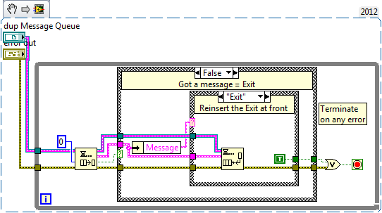
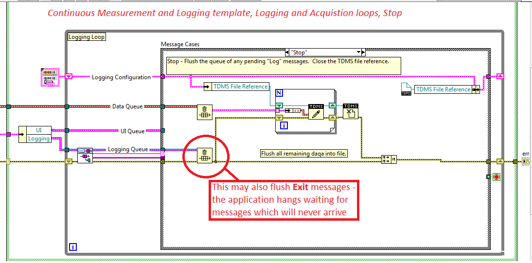
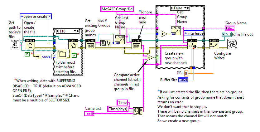
The model of continuous measurement and logging in LabVIEW 2012SP1 has a flaw in the Acquisition and recording loop.
Stop messages manager ignores all messages in the queue of messages. The note says:
"Stop - empty the queue of all pending messages 'Connect'. Close the reference of TDMS files. "See the picture below.This concept breaks if the output message is issued while the Stop message is being processed. The time gap critical to do this is small, because the issue is posted on the front of the queue. But it depends on the treatment in the case of the Manager to stop. Large or small - it can happen.
The symptom is the application block in an infinite waiting on the queue of message - all commands have no effect, as the rest of the loops are completed. Break terminates the application. Pause button doesn't work anymore. (see this entry forum)
This problem may appear only after enforcement has become more complex and the schedule has changed - the fresco made model works and does not reveal the question.The cure: first of all I thought to preview the elements of the queue before they are scrapped selectively, one by one in the loop to stop, but that usually is not working either, because the output can happen precicely in the laps of time between overview and dequeue - don't forget no outputs are displayed on the front of the queue.
I think the best option is to replace the flush of the queue in the Stop messages with a selective messages waiting managers one by one and check if the output is - if so, reseat it in the front of the queue. All other messages are discared. That look like this, have seen interesting parts...
Here is the message loop to stop with the problem highlighted.
As I'm not mistaken, I think it's better that NEITHER updates the model to avoid this problem.
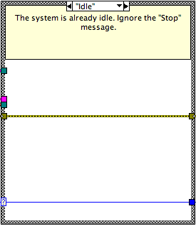
Here is the case of the resting State in the case of stop message:
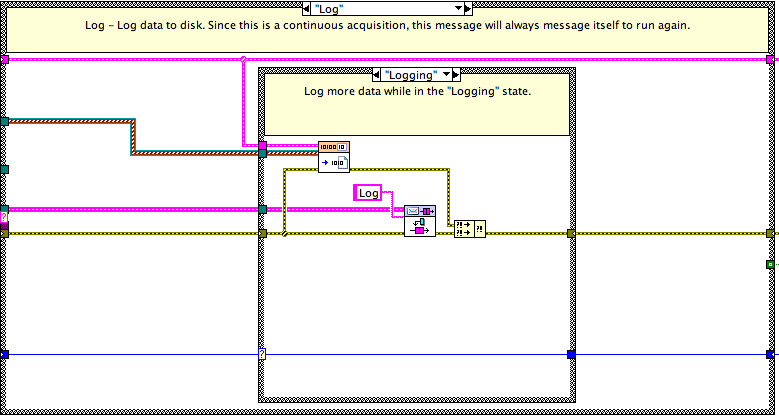
Us do not hang the CPU run a constant stream of messages ineffective because we only "Log" enqueue messages when we are in the valid state logging (a State of rest here is again a passthrough).
The worst case, it's that there are number of register requests already in the queue when the system shuts down. After receiving the stop idling message, state transitions and other Log messages become non - ops due to the State.
I consider the opportunity to post a few screws update
~ Simon
-
Scaling of the continuous measurement and logging (OR-DAQmx) model
Hello
I managed by reading the analog input of my 6210 USB and NO using the model of logging (OR-DAQmx) and provided continuous measurement. However, I need to convert the voltage signals to the pressure.
How I change the model to achieve this? I've read about DAQmx create Scale.vi and creation of scales in MAX, but I'm not sure where/how to apply them to the model.
Fine thanks
Ben
In the loop Message of Acquisition VI is a case to launch Idle. Here is where the task of data collection is initialized. In both of these screws is where you add the code to create the scales and apply them to your analog inputs.
-
How to read and write attributes using the API?
I'm trying attributes of access (read and write) of the following:
SequenceFile
Sequence
The sequence steps
When you look at the documentation of the API, TestStand, the following functions are available:
PropertyObject
Properties
Methods
I tried to use the SetValString and GetValString commands using the reference of the attributes, but it does not seem that the data is stored in the file.
I can't find the following information in the TestStand API:
- Where the attributes are stored in a property object?
- How can we access through the API?
No advice and no information is appreciated!
You must increment the number of changes to the file after that editing the sequence editor (or UI) won't refresh or mark the file, as amended. Use sequenceFile.AsPropertyObjectFile (). IncChangeCount().
SequenceFile attributes are stored in the SequenceFile.Data, not the object of SequenceFile object. You can change them in the Advanced tab of the properties of the file sequence dialog box.
Hope this helps,
-Doug
-
How to continually take and record waveforms with neither 5102
a machine generates waves sinusoidal time randomly. I want to permanently take and record waveforms in 10s by NI 5102.
How to do?
Thank you very much!!
Thanks for the review! but this isn't a supported NEITHER.
I record signals by this method.
and the promble news is that different sampling frequency, the different wavelength. for example, when I put the sampling frequency is 4 k, the wavelength is 12 seconds if the sampling frequency is 10 k, the wavelength is 8 seconds the signal under test 1 k, the time constant is 10000.
now, I save waveform to 10 sec. What is the best relationship between sampling frequency and the time constant?
-
Temperature measurement and the CJC using thermocouples on a USB - 6229 BNC
Hello
I'm trying to get the measurements of temperature using type K thermocouples on the box nor usb-6229 BNC. SignalExpress software doesn't let me choose 'Built In' to the Source of the CJC. So, I must select 'Constant', which means that I then have to follow the evolution of the temperature during the day with a separate meter and adjust the value of CJC accordingly to maintain an accurate reading. Is there a way around that to avoid having to monitor the room temperature at the junction?
Thanks in advance
Mike
Hi Mike,.
It seems that you have managed to find a solution for you have this problem, which is great news.
However, for future use, if you had bought the 6229 with massive ending (rather than the interface BNC) then you might have interfaced unit with a block of connection SCB-68 (see link)
http://sine.NI.com/NIPs/CDs/view/p/lang/en/NID/1180
The SCB-68 has a CYC source built-in, so you might have used in conjunction with 6229 (mass layoffs).
A bit of in the way, but I thought you may be interested.
Best wishes to you all
-
Adobe Application Manager, and write permissions using Cougar
After you have installed the Trial Version of Photoshop CS6, I tried using Photoshop CS6 v. 13.0.1 update so that CS6 could read my Nikon D800 Neff files. We're trying to install, window warning PS Application Manager indicates that user/ber.../library/application support/adobe / doesn't have write permissions. and will not let me install step. I checked the permissions and the location has write permissions so am a little loss to know what to do to allow me to install the file raw drive? Hoping you can help? Using MBP 15 "running Mountain Lion OSX 10.8.2 (latest version I think) thanks for any help here.
Have you tried to apply the permissions to write to all closed objects? You could also try to temporarily create a new administrator account and try to apply the update under this account.
-
Keithley 2000 not identified NOR Measurement and Automation Explorer using GPIB
Hello
I recently used NI TestStand and NI MAX with IVI drivers to get my working(using USB) peripheral. He has worked successfully for TG5011 and TDS1002B Oscilloscope function generator.
Following the same procedure: I started with 2000 model DMM of Keithley with GPIB.
I am facing difficulties in finding my camera on OR-MAX devices and interfaces. I use a GPIB KUSB - 488B USB adapter to connect.
I can interact with the device of VISA Interactive Control and KUSB diagnosis tool and you can see the device in the device Windows and KI-Configuration Utility Manager. Surprisingly, I don't see GPIB Board in the NOT-MAX.
Help, please.
System details: NI-VISA 5.2 installed on Windows 7, KUSB-488 driver installed in command compatibility mode OR. (only ieee_32m.dll is present), installed UN NOR-488.
Thank you
Martin
To help all those who have read this thread:
I had the Keithley 2000 NOR-MAX and NOR-Test Stand using IVI Driver (for Keithley 2000 of NOR) using the KUSB - 488 B (GPIB to USB adapt from Keithley).
Layer of keithley installed IO Keithley and I can see the unit property. I then followed the procedure for IVI MAX and TestStand pilot program and IT WORKED!
Please find attached the screenshots for Visual clarity.
Thank you and best regards,
-
Lsass.exe on Vista constantly reads and writes three times. How can I stop this please?
After starting calm down. Task Manager indicates that LASS. EXE continuously reads and writes. It shows three readings and three written a couple of times per second. The readings are still 204 bytes and the writing are always 132 bytes. This action stops.
I searched the web for answers and tried all the suggestions and nothing worked.
Any ideas please?
Hello
I suggest you go through the link that talks about a similar problem.
You can also post your question to:
http://social.technet.Microsoft.com/forums/en-us/itprovistasecurity
-
record data continuously using PDM
Hello
I'm new to LabView and sought some means of recording of analog data using PDM. I tried to implement in my code but found that when I open files created with excellent I get gibberish and no data value. I enclose a photo of part of my code that is responsible for this.
DAQ Assistant called the values of two analog voltage inputs (two Photodetectors). The signals are displayed just fine and continuous via waveform graph, but I want to record these values as well. I tried to use Write to Spreedsheet but only a certain value (100 samples) were recorded at the time. I want that all THE values from these two analog inputs at that time, I click START on time I click STOP.
Thank you!
Alfredo
So, I guess that it is placed in a loop. Well, you are always 'creation' a TDMS file on each iteration of the loop instead of using "open and create" TDMS open and add the data. Yet once again, take a look at my instructions to search in the Finder of the example. After the back if you have additional questions.
-
Hello
I want to generate the continuous signal and at the same time I want to read that signal that I generate using a single card DAQ. I want to generate signal and the received signal is synchronized and in phase.
I looked at several samples on the sync, but it quiet confusing. One using the same clock of entry while the other use a trigger to start. I use the PCI-6024E DAQ card.
Can someone help me in this regard?
In two of these screenshots, the task to HAVE started first (that's what you want, because it is the task of the slave).
Typically for AO, you can simply write a unique period of your waveform, and then regenerate again and again. Your waveform would be preset before the task starts. If you need to update the waveform on the fly according to enter programming during execution of the task, you would disable the regeneration. In addition, if the wave form is such that it cannot be easily represented by a predefined buffer (for example, it is a strange frequency which is not a same ditch at the bottom of the sample clock), then non-regeneration is the way to go.
Best regards
-
LV2013, Win7, LVRT 2013, PharLap ETS 13.1
I have a code that works well on Windows I want to move to the area of RT.
I use the function PDM, but not need high performance for this (I'm going for other things later).
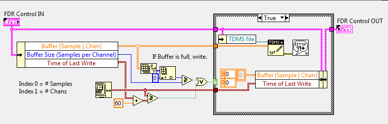
Here is the code of the OPEN FILE. Once again, with the exception of how the LIST OF NAMES comes to be, it is a copy of the code on the Windows desktop.
Here is the code that actually writes the data. Nothing fancy, just see if the buffer is full, and write in the affirmative.
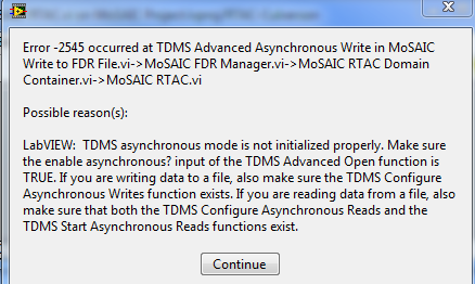
The problem is, I get an error-2545 to the WRITE function:
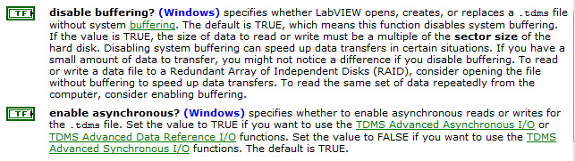
It is said to "make sure that the option enable asynchronous? entry service TDMS Advanced Open is TRUE."
The default value is listed as TRUE, well, I'm not wiring it. I tried a REAL wiring to it without change.
But he also described the HELP text with a qualifier "(WIndows). What happens if use you it somewhere else? AID is not worth to say.
It is said "If sure the TDMS Configure Aysnchronous function writes exists". By "there," I guess that means 'is called', but it is in the OPEN above procedure.
Here, aid is also skilled with a qualifier "(Windows). What happens if use you it somewhere else? AID is not worth to say.
I missed something that says 'you cannot use TDMS on platforms other than WIndows', or you must set the property 'not-being-stupid' true, or something?
EDIT: Here's the help text:
I agree that the error message is confusing in this case.
The best performance, you can get on RT uses the synchronous mode of PDM Advanced API. An example in LabVIEW is very good to start
-
I use the PCI-6723 card and I am trying to produce a model of waveform using the analog output channel. The wave consists of 5 different voltage levels. The main problem is that the first 4 voltage levels are supposed to have 926 microseconds time intervals and the time interval the last voltage level is supposed to be 1,296 milliseconds. In addition, the waveform must be triggered on the trailing edge of a sample clock of 200 Hz with a 0.1% Duty Cycle. Is it still possible? If so, any help would be greatly appreciated. Thanks in advance!
Here is what I currently have, but it does not fulfill my purpose.
 int32   written;
    float64 data[5] = {-0.23, 0.38, 1.12, 1.78, 0.10};  //volts
    //long  time[5] = {  926,  926,  926,  926, 1296};  //microseconds

    // DAQmx Configure Clock
    DAQmxErrChk (DAQmxCreateTask("",&taskHandleFRQ));
    DAQmxErrChk (DAQmxCreateCOPulseChanFreq(taskHandleFRQ,"Dev3/ctr0","",DAQmx_Val_Hz,DAQmx_Val_Low,0,200,0.001));
    DAQmxErrChk (DAQmxCfgImplicitTiming(taskHandleFRQ,DAQmx_Val_ContSamps,1));

    // DAQmx Start Code
    DAQmxErrChk (DAQmxStartTask(taskHandleFRQ));

    // DAQmx Configure Code
    DAQmxErrChk (DAQmxCreateTask("",&taskHandle));
    DAQmxErrChk (DAQmxCreateAOVoltageChan(taskHandle,"Dev3/ao0","",-10.0,10.0,DAQmx_Val_Volts,NULL));
    DAQmxErrChk (DAQmxCfgSampClkTiming(taskHandle,"/Dev3/Ctr0Out",1000.0,DAQmx_Val_Falling,DAQmx_Val_ContSamps,5));

    // DAQmx Write Code
    DAQmxErrChk (DAQmxWriteAnalogF64(taskHandle,5,0,10.0,DAQmx_Val_GroupByChannel,data,&written,NULL));

    // DAQmx Start Code
    DAQmxErrChk (DAQmxStartTask(taskHandle));
Bingo. This code seems to work much better. Looks like I had to reduce my number of samples per 1 to fit the waveform desired in 5 milliseconds of the sample clock delay.
However, if someone knows a better way to achieve these results, I am open to all ideas.
void CDevDlg::OnRdr1e1()
{
    float64     data[4000];
    float64     volt[5] = {-0.23, 0.38, 1.12, 1.78, 0.10};  //volts
    int x=0,d;

    for(int v=0; v<4; v++)
    {
        for(d=0; d<741; d++)
        {
            data[x++] = volt[v];
        }
    }
    for(d=0; d<1036; d++)
    {
        data[x++] = volt[4];
    }

    // DAQmx Configure Clock
    DAQmxErrChk (DAQmxCreateTask("",&taskHandleFRQ));
    DAQmxErrChk (DAQmxCreateCOPulseChanFreq(taskHandleFRQ,"Dev3/ctr0","",DAQmx_Val_Hz,DAQmx_Val_Low,0,200,0.001));
    DAQmxErrChk (DAQmxCfgImplicitTiming(taskHandleFRQ,DAQmx_Val_ContSamps,800000));

    // DAQmx Start Code
    DAQmxErrChk (DAQmxStartTask(taskHandleFRQ));

    // DAQmx Configure Code
    DAQmxErrChk (DAQmxCreateTask("",&taskHandle));
    DAQmxErrChk (DAQmxCreateAOVoltageChan(taskHandle,"Dev3/ao0","",-0.5,2.0,DAQmx_Val_Volts,NULL));
    DAQmxErrChk (DAQmxCfgSampClkTiming(taskHandle,"",800000,DAQmx_Val_Rising,DAQmx_Val_ContSamps,4000));
    DAQmxErrChk (DAQmxCfgDigEdgeStartTrig(taskHandle,"/Dev3/Ctr0Out",DAQmx_Val_Falling));

    // DAQmx Write Code
    DAQmxErrChk (DAQmxWriteAnalogF64(taskHandle,4000,1,10.0,DAQmx_Val_GroupByChannel,data,NULL,NULL));
}
Maybe you are looking for
-
I've just updated to the latest version of Firefox 32.0.3 today and now I can not manually type in the URL. I can't get to a new page if I click on a link. I had to use - gasp - Chrome just to get to this help page! I tried to restart Firefox.I can t
-
How can I avoid 7.0.1 update to new versions without my permisssion?
I continue to reinstall 7.0.1 and it maintains to 8.0.0 without myknowledge or consent. I don't want to keep losing support of Add-ons and extensions every two days with the new versions.
-
SkypeSetupFull keeps freezing.
(Sorry for my English) I had no problem with Skype, last week... But since I wanted to re - install (last version 6.16), it keeps freezing at the first step: Installation of Skype current (current Skype Instalation). It loads forever and nothing happ
-
Derives from NI USB 6363 signals (differential Setup)
Hello! I just changed a task of data acquisition of 2 signals of "CSR" to "differential". After that, the signals set to reflect really bad. Did this happen because I have not yet hooked the acquisition of data the source of real tension? This loop i
-
I just started using a computer, please try to be patient. A friend gave me his old laptop, a Dell with Microsoft Vista professional. In my case, I use Notepad. In this format, I try to write stories and they appear in the DOCUMENTS. I have inserted