Control the properties of the graph of a waveform for waveform table.
I'm to customize a waveform graph. I will have no problem using nodes property to define all the things I need to (color plot, the names of axes, etc...). My wave form is actually an array that contains the seven waveforms. The problem is that the property of the waveform graph node changes only trace, legend, etc. the first signal in the graph. They all have the chart perfectly together. However, my application requires the user to be able to select say signals 2, 5 and 7 of the table. When it does, it receives signals of 2, 5 and 7 on the chart, but the legend Watch reports 1, 2 and 3 and they draw in the colours of the signals 1, 2 and 3. Any suggestions on the update of the properties of several plots of a waveform graph?
Also when I want 1 signal trace a curve of waveform. When I want the signals from 2 to 7, I have to draw a second copy of the curve of waveform. For some reason any a waveform table chart cannot double as a unique waveform graph. Any ideas on that? Thanks in advance for your help.
To change the properties of other signals in the chart, you will need to set the ActivePlot property node before writing the color, the name of legend, etc... To display only the selected signals, you could do a couple different things.
(1) set the color of the signals that are not visible by transparency
(2) write NaN values to the curve of waveform of the signal that you do not want to display
Tags: NI Software
Similar Questions
-
Hi, I have two decimal strings, each of them contains the numbers change over time. I want to plot them on the graph XY, a string for each axis. Can you show me how do?
This is not a formula, but a constant simple schema of a table complex. Wire remains, then do a right click of the terminal of the initializer of the feedback node and select "create constant. That should do it.

-
Cannot control the color sensor in LabView for Mindstorms
Hello! New here.
I'm currently boning on LabView via 'LabView for Lego Mindstorms' for a possible job in the near future, and I encountered a problem from the beginning.
I am programming my brick Lego of LabView to simply activate the color sensor which is quite easy: I'm building a while loop and inside I have a block of color sensor attached to a block of text that displays the light intensity of the probe in the text on the brick. I compile and run the detector turns on and I can read the intensity constantly updated on the brick. This part works fine. I would now like to control the light sensor (that doubles as a light source with color LEDs) on the front of the LV Panel. The book I'm using (LabView for Lego Minstorms) says I should block sensor on the entry "generate light' do right click and choose"Create--> Control"in the menu that appears. A Boolean command button should appear connected to the sensor block in the block Panel and a push button should appear in the front panel. This is not what is happening. Here, the two things are different.
(1) I have no port "generate light" click on right-click. This is probably using a version more day of Mindstorms that uses of the book. It's a matter of book/Mindstorms, which probably cannot be resolved here but I hope that the next issue of problems will make it irrelevant.
(2) I right click and create the control, but rather than create a Boolean command button as the book predicts, it creates an icon "BrickReference.lvclass". He connects very well with the light sensor and a corresponding block is created in the front panel, but it is a paper weight that I can tell. I can't do anything with it. There are no buttons to push, no slider, button, button radio etc and I can't seem to change into something that somehow work. I have delete and don't create a no kidding Boolean button from the library, but it does not connect to the photoelectric cell and so I can not compile. So now, I'm a little stuck.
I searched "Reference of the brick" online in the context of LabView class and have found little or nothing that talks about its definition or how I can use it to control the light via the front panel sensor. Help with the software section is not much help, and yet I'm sure there must be a way to control a simple Lego light sensor of the façade for debugging purposes and others.
If you know what I'm doing wrong or if you know a finish around this issue that will allow me to control a Mindstorms brick from the front in this way, please let me know.
Thank you!
Try to post in the forum of Lego.
http://forums.NI.com/T5/LabVIEW-for-LEGO-MINDSTORMS-and/BD-p/460
-
Using an algorithm of scaling of the graph of a waveform within a Subvi invisible?
Hello
I have a little problem with the automatic scaling of the graphs.
First of all:
For automatic scaling of the axis LabVIEW uses the set of data that was sent to the curve. If I zoomed in on the inside, the automatic scaling always uses all of the data even if it is not visible at the moment. To resolve this problem, I read on the positions of the zoom sliders and values min/max within this area of research. This method works.
Second:
Now, I want to the scale of the axis using the specified min/max values. Labview graphics using a special algorithm of scaling according to the format of the axis. I want to use it, so my idea was to send the cut data and format of the axis to a Subvi. Inside this Subvi, I use a waveformgraph to display the cut data and run an automatic scaling once. Now, I read the values min/max of the graph and set this values on the main chart, I see in my program.
The result is, my main chart shows the data zoomed area in maximum size (to the axis scale) and hole data is always available, so I can still pass the data in the chart or others.
Problem: The sense of scale with a grpah inside a Subvi only works if the chart inside the Subvi is visible. If it isn't, no scaling would be made. My solution is to open the Subvi as a small window and close automatically after the scaling. It's not very nice.
Are there any other ideas how to use auto scaling without showing the front of the Subvi?
Thank you very much and best regards,
Michael
Hi Michael,
-show your façade out of the visible screen area, so the user does not notice the window...
-Make your own algorithm of scaling based on these values min/max...
-
Dynamically hiding / display the curves on the graph of a waveform
Hello
Is it possible for IT (OFF) dynamically a particular curve on the waveform table.
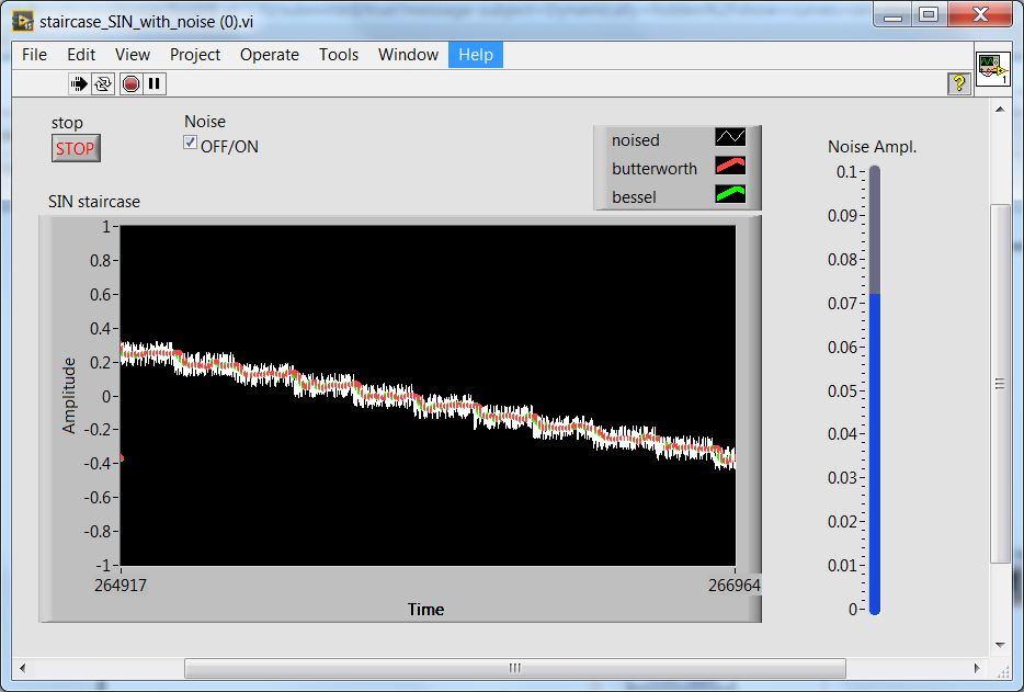
Here is the example below - 3 curves are superimposed and to see a particular curve, it would be nice to have one option on OFF other curves (e.g. using checkbox).
Thanks in adavnce.
Pavel
It's actually a built-in function.
Right click on the legend to draw. Select the visible items > trace visibility box.
-
Web Service data control the result as a basis for workflow router
Hello
I'm under JDEVADF_11.1.2.3.0_GENERIC_120914.0223.6276.1 build
I want to use the result of a check of SOAP Web Service data as input for a router on a workflow; lines will only ever return 0-1 control of data.
Is it possible declaratively on the workflow diagram by simply using a SOAP data control, or should I access the data control through a managed bean, or go on the road of web service proxy?
I'm new to ADF some detailed guidance would be appreciated.
Thank you very much.Hello
routers can have their own binding ADF file, so yes its possible. Select the router and then use the right button of the mouse to go to the pageDef file. As it does not exist it will be created. Then add a method binding point to the method on the WS to invoke domain controller. In the router, you should be able to use #{bindings.methodName.execute} as the EL. If the method returns a value, then it went to the assessment.
However, if you need to look at an iterator (returned collection) then you are binding the attributeValue to one of the attriibutes in the collection. This should also configure the WS iterator and the required method binding
Frank
-
How to control the current program view lab for a power E3631A agilent
Hello
I wrote a program to view lab for agilent E3631A triple output power supply in constant voltage mode, and I want to update to operate in constant current mode also. But I can't find any function in the Instrument of e/s, which is related to the current but only the current limit I already used to write my programs to the constant voltage mode. How can I do this?
Thank you
When the current exceeds the current limit, the power supply will be running constant. The food isn't really have one running constant set.
-
Single request for the display of all, but the values of 1 column for all tables
Hello
All tables have the column SYS_CREATION_DATE.
But I don't want to not display the value of this column
Can anyone suggest a way in which I could achieve this?
Oracle version: 11 GR 1 material
OS: SunOS
See you soon,.
Malika
Published by: user9131570 on July 6, 2010 19:57user9131570 wrote:
@TubbyI * table-wise display the values of all but 1 columns (SYS_CREATION_DATE) in my database.*
I need it to compare to another data base for all these values.
I would like to make a wild guess at what you are getting.
In view of these two tables
create table emp
   (empid number,
    empname varchar2(15),
    empaddr   varchar2(15),
    sys_creation_date date);
--
create table dept
   (deptid number,
    deptmgr varchar2(10),
    sys_creation_date date);
you want to combine somehow
select empid,
         empname,
         empaddr
from emp;
with
select deptid,
         deptmgr
from dept;
in a single sql statement?
-
Import of SVG images in DITA topics / controlling the size
Hi writers,
I am currently evaluating DITA using FM9 p250 and the DITA FMx plugin. If we adopt DITA, should be a replacement for vector graphics formats, that we currently use. I am considering the SVG to cause the return options. We could use Illustrator or Visio to create. I created a few sample files and imported in a DITA topic, but I can't seem to control the size of the screen.
When I use the - import - file, the size in the import dialog box settings seem to have no effect. I can then scale the image via the properties of the object, but I lose these changes when the topic is closed.
I think that someone has reported a problem with SVG and 8 FM in this forum. This behavior is a known bug, even in FM 9, or I do something wrong when importing?
Are there attributes DITA, I could put to control the size?
Thanks for any help
Susanne
Hi Susanne...
It doesn't seem to be a bit of a bug in FMx when it comes to SVG. If you have activated the option 'Use fmdpi', you should turn that... It seems to conflict with sizing of SVG. If this option is not, when you insert an SVG image, you can then resize the image as necessary using Esc, g, o (or graphics > properties of the object) and by setting the values of width and height. Do not set the values of height and width in the attributes, use the object's properties dialog box.
Also... remember to set the size of the image, not the framework. FMx "shrinkwraps" the frame to the image in order to select the image you just click in the middle of the image, not the edge... by clicking on the edge will probably choose the framework. After you set the size of the image, the framework must readjust to the new size of the image... If it doesn't, try saving the file, this re-shrinkwraps images.
You should be able to set the size of the SVG but... works for me.
See you soon,.
.. .Scott
Scott Prentice
Leximation, Inc..
www.leximation.com
-
Visualization of more values on the graph of the DAQ card
Hello
I acquire a Signal using the data acquisition card, the problem is that I can view only a few values on the graph of a waveform. Guide kindly of me if I want to see the points more on the graphical waveform, what I would do in my programming window.
Concerning
I think that you just want to use a TABLE instead of a chart. A graph has an associated history, so that it shows more that just the last data series acquired you and wrote to the curve.
-
The export of certain values of the graph xy to the worksheet
Hello
I'm newish to labview and I'm trying to extract the values used to draw the graph XY, but only for x = 0, 10... 90, 100... 360.
instead of extract values 361, I only need 37. I tried to use another statement, but with no success.
Any help?
Or use the table decimate for each 10 value in the input array.
Mike...
-
dispplaying data on the graph of waveform inside/outside while loop
I create a vi using the random number generator, entering the number in the function(express>>arithmateic>>maths>>trig>>sine) fishing and connect the output of the function sine waveforms. Table of waveform show no problem. If I replace the with graphic waveform table, I get an error that the source type is differenct type of sink. I then put waveform chart outside loop everything hoping that tunnel would act as a table, but still I get the same error. I then put build table palette between all border and loop waveform graph which is placed outside the while loop. I get no error, but no data is displayed on the graph of a waveform. Theoretically, if I press stop I would see a distorted sine wave on the waveform graph, but this doesn't seem to be the case. I am wondering how to view data on the graph of a waveform in such cases!
Thank you in advance for reading and help!
See you soon
First of all, you can take a part of the basis of LabVIEW tutorials.
Since you need to work with a chart and it is the preferred method to display data point by point, I don't know why you try to use a chart. In any case, you cannot use all simply a table of generation because that would be just the result of the last iteration and your graph indicates it is a single point. If you activate autoindexing, then you get all the values, but not before the end of the loop. If you were to use a shift register and the build dashboard, you might place the graphic inside the loop, but then you would face performance issues that the table would grow uncontrollably.
-
How to control the quote on NAS devices by windows server 2008 R2?
Dear all,
I have Windows Server 2008 R2, and I have an important investigation concerning the control of quotes on my NAS device.I have a LaCie 2big Network 2, connected to my network and I copied all my data on it, my shared folder is public, so its accessible without credentials and its already shared and accessible by all users.I want to control the subfolders with specific citation for each user and control which extensions to be used by Windows Server 2008 R2.So any help to get there?Kind regardsAbdelaal,Hello
Your question of Windows 2008 is more complex than what is generally answered in the Microsoft Answers forums. It is better suited for the IT Pro TechNet public. Please post your question in the Technet Forum. You can follow the link to your question:
http://social.technet.Microsoft.com/forums/en-us/category/WindowsServerHope this information helps.
-
How to set the properties of the graph XY via VI Scripting plots
Hello
Is there a way to change the properties of the graph XY plots in a VI script?
Main VI, I create an XY chart in another VI in a VI script. Now, I want to change caption of the field names and their styles etc. I notice that these properties can be implemented in the new VI (see screenshot graph Node in NEW VI.jpg property). However, I could not see these properties by calling the property node of graphical reference XY main VI (see screenshot).
Thanks for the reply due.
Concerning
HB
Hello, HB,.
Maybe you need to use a XYGraph refnum rather than a refnum graphChart.
ULI
-
Control of the cursor on the graphs
Hello
In my testbend to the experience and I want to add some graphics facilities on a chart.
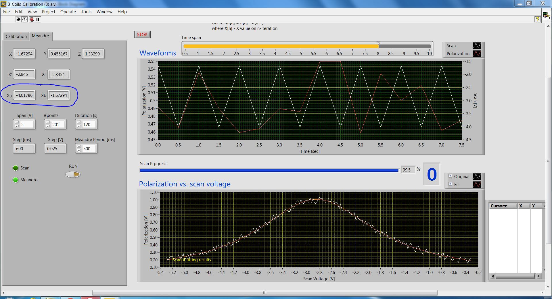
For example, taking a snapshot below; IWant to see the location of the Xa and Xb points on the graph at the bottom.
After reading a few posts, I undestood that the best solution for this kind of thing is using the sliders.
If this is the case, I need to add a slider 2 (in emissions way, if possible) and then control them using some clues.
There are some examples that show how do.
Thank you.
PS Ce would be as well to "bulbs" on the location of the points.
> It would be as well to "bulbs" on the location of the points.
That is the question for the OR. You can select cursor point style, but you cannot change its size. When you change the size of the cursor, it affects only the thickness of line to cursor and you can get only big vertical cross, not just any what piont of style as you do with graphics. At least, LV2011, may be they fixed that in 5 years seems sufficient.
Maybe you are looking for
-
Boolean Array controlled clock reentrante Subvi
I am in the final stage of implementation of my program. Currently, I have to overcome two obstacles. #1 corresponds to the attached VI "my chronometer. The round LED starts to count time and stops him. Problem is even if I turn it off it, the timer
-
No sound after clicking OK for review to free disk space.
Hi all. Hi my friends young son received a notice it is computer saying he was running out of disk space and the computer could take these steps to free up space. Well you know kids, he presses OK before asking one. Now, there is no sound on the comp
-
How can I re - install Windows XP after a virus without disks?
Can someone help me please l have a friend that took the pc a virus got rid of he couldn't do anything so called T-mobile where he was its dongle they said that it was not they told to remove windows xp that there no disc to install in pc is there an
-
iTunes open habit, giving "Data Execution Prevention" as being the reason
Can someone help me understand how to get iTunes to work again. Windows is preventing opening citing 'Data Execution Prevention' as a reason. System Restore is only with dates of up to a week ago and I need to go further so I can't fix this way [bad
-
New ink cartridge does not print red
I replaced the ink cartridge and it won't print any red color, all other work